Table of Contents
Advertisement
Quick Links
Transponder-Antenna
HG G-71450/1/3/5-A
PosiPulse & Transponder-Code
Variants HG G-71450-A (RS232) / HG G-71451-A (Profibus) /
HG G-71453-A (CANopen®) / HG G-71455-A (Profinet)
English, Revision 02
Innovation through Guidance
Date: 06.06.2019
Dev. by: WM/LF
Author(s): RAD/WM/LF/RF
www.goetting-agv.com
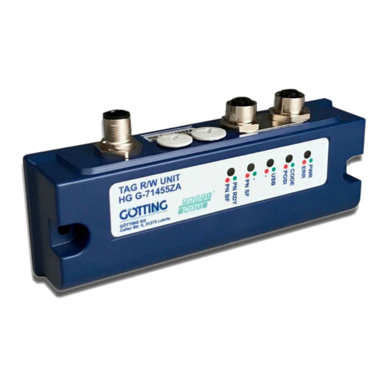
Transponder
Photo: Variant
HG G-71455ZA
Advertisement
Chapters
Table of Contents

Related Manuals for Gotting HG G-71450-A


Summary of Contents for Gotting HG G-71450-A
- Page 1 Transponder Transponder-Antenna HG G-71450/1/3/5-A PosiPulse & Transponder-Code Variants HG G-71450-A (RS232) / HG G-71451-A (Profibus) / HG G-71453-A (CANopen®) / HG G-71455-A (Profinet) English, Revision 02 Date: 06.06.2019 Dev. by: WM/LF Author(s): RAD/WM/LF/RF Photo: Variant HG G-71455ZA Innovation through Guidance...
- Page 2 Overview Summary Characteristics of the transponder antenna HG G-71450/1/3/5-A: • Transponder-Antenna for the posi- • Connectors (depending on the vari- tioning of automated guided vehi- ant): Up to 3x M12 cles (AGV) • Data interface (depending on the • Indoor, IP 65 variant): RS 232 (serial), Profibus, CANopen®, Profinet (with inte- •...
-
Page 3: Table Of Contents
Table of Contents Contents About this Document ................ 6 Warning Notices ........................6 Symbols ........................... 7 Definitions of Terms......................7 Abbreviations ......................... 8 Introduction ..................9 Variants ............................ 9 Additional Products ......................10 Additional Documents ....................... 11 Operating conditions ......................11 Application Examples for the Automation .............. - Page 4 Table of Contents Transponder Antenna ......................24 4.3.1 Mounting Holes .......................25 4.3.2 Connection Cable ......................25 Interface HG 06150Y (optional for HG G-71450) ............26 Commissioning ........................27 Interfaces: RS 232/serial (HG G-71450) ........28 Interface Parameter RS 232 ....................28 Telegram Setup ASCII Coding (SW5 = ON) ..............29 Telegram Setup of Binary Coding (SW5 = OFF) ............30 Resetting the Antenna .......................30 Transponder Programming ....................30...
- Page 5 Table of Contents 10.1 Positioning of the Transponders using HG G-71325 as an example ....61 10.2 Programming via the Monitor Program ............... 62 10.3 Programming via Interface Telegrams ................. 62 10.3.1 HG G-71450: Programming via Serial Telegrams ..........62 10.3.1.1 Structure of the Telegram (Host ->...
-
Page 6: About This Document
Chapter 1 – About this Document About this Document For you to be able to use your product simply and safely this device description uses consistent warning notices, symbols, terms and abbreviations. Those are described in the following sections. 1.1 Warning Notices In this device description warning notices appear before sequences of actions that may lead to damage to persons or property. -
Page 7: Symbols
About this Document – Chapter 1 1.2 Symbols In this device description the following symbols and formatting are used: If this information is ignored, the product may not be operated in an optimal way. Indicates one or more links to the Internet. –... -
Page 8: Abbreviations
Chapter 1 – About this Document 1.4 Abbreviations Automated Guided Vehicle Radio-Frequency Identification RFID Electronic Data Sheet, configuration file for CAN bus systems General Station Description, device master data for Profibus and Profinet devices Device Description HG G-71450/1/3/5-A | English, Revision 02 | Date: 06.06.2019... -
Page 9: Introduction
Introduction – Chapter 2 Introduction Data transmission between various objects (tool carriers, tools, vehicles, etc.) and the control system is crucial for ensuring the operating procedure. Movable objects must be identified and positioned quickly and reliably. Thereby identification sys- tems offer a safe, easy to install and economical solution. They can be used to man- age and monitor processes. -
Page 10: Additional Products
Chapter 2 – Introduction 2.2 Additional Products The following products of Götting can be used with the transponder antenna (note variants). Rod transponders are usually installed in the ground, disc transponders usually on the ground. The rod transponders listed below have a slightly higher transmission power than the disc transponders. -
Page 11: Additional Documents
Introduction – Chapter 2 Additional products (part 2 of 2) Table 3 Compatible with transponder antenna Order-No. Description HG G-71450 HG G-71451 HG G-71453 HG G-71455 ZA YA XA Transponder (flat disc) HW DEV00130U 125 kHz, pre-pro- grammed Transponder program- ... -
Page 12: Application Examples For The Automation
Chapter 2 – Introduction When changing the direction of travel, incorrect PosiPulses can occur as a mat- ter of the principle. Changes of direction should therefore be avoided in the sys- tem or compensated in the evaluation. For this purpose a PosiPulse delete command can be given via the data interface, for example. -
Page 13: Scope And Function
Introduction – Chapter 2 As soon as a transponder is within the reading area of the antenna, it is supplied in- ductively with energy by the energy coil without contact and then cyclically sends its code back to the antenna at half the transmission frequency. Otherwise, the tran- sponder is completely passive and does not require a power supply or battery. -
Page 14: Figure 3 Detection Areas, Top View
Chapter 2 – Introduction Detection areas, top view Figure 3 direction of travel F detection area magnetic field lines line A reading antenna transponder area 1 area 2 Only a maximum of one transponder is allowed in the detection area of the antenna at all times! The following image shows several transponders to explain the different transponder positions. -
Page 15: Signals And Timing
Introduction – Chapter 2 2.7.3 Signals and Timing Signals and Timing Figure 5 direction transponder antenna area 1 area 2 transponder detection area antenna length signals and timing data-free area (detection gap) level signal (CD) Midpoint Crossover = Midpoint pulse time (duty cycle of the PosiPuls) = 100 ms (positioning signal) (not scaled) At first the data is „uncertain“... -
Page 16: Hardware
Chapter 3 – Hardware Hardware 3.1 Transponder The Götting transponders listed in Table 3 on page 10 are used as reference marks in the ground. The transponder code consists of 16 bits. 3.2 Transponder Antenna (Variants) 3.2.1 Applies to all variants The antenna system is located in a 156.5 x 31 x 53 mm (L x D x H) housing made out of PC (polycarbonate). -
Page 17: Transponder Antenna Hg G-71450 (Rs 232)
Hardware – Chapter 3 Connection options PosiPulse Figure 6 HG G-7145x HG G-7145x +24 VDC +24 VDC Posi Posi Pulse Pulse Posi Posi Connection to a PLC Connection to a Relais 3.2.2 Transponder Antenna HG G-71450 (RS 232) The connection of the antenna occurs via a 5-pin cable. The ST 1 connector is a M12 circular connector (see Figure 7). -
Page 18: Leds
Chapter 3 – Hardware 3.2.2.2 LEDs 4 LEDs are provided for function control: HG G-71450: Meaning of the 4 LEDs Table 5 Meaning Indicates that operating voltage is available DATA is permanently lit when a transponder is in area 1 (see Figure 2 on page 13) –... -
Page 19: Pin Assignments
Hardware – Chapter 3 3.2.3.1 Pin Assignments HG G-71451: Pin assignment of the 5 pin circular connector ST1, male, A-coded Table 6 ST1, male, A-coded Assignment POSI out (20 mA) TxD (RS 232) *) RxD (RS 232) *) GND (data and supply) The specifications TxD and RxD refer to the antenna. -
Page 20: Switch-On Behaviour
Chapter 3 – Hardware 3.2.3.3 Switch-on Behaviour After applying the operating voltage, the positioning output is active for the duration of the reset (approx. 500 ms). To check their function all LEDs except the BUS-LED are switched on for 500 ms. After approx. 2 s the device is ready for operation. 3.2.3.4 Profibus-Interface For this antenna the data as well as a status byte are transmitted via the Profibus. -
Page 21: Leds
Hardware – Chapter 3 HG G-71453: Pin assignment of the 5 pin circular connector ST2 (socket) Table 11 ST2, female, A-coded Assignment n. c. *) n. c. *) CAN_GND CAN_H CAN_L The pins 1 or 2 are connected between ST2 and ST3. HG G-71453: Pin assignment of the 5 pin circular connector ST3 (pin) Table 12 ST3, male, A-coded... -
Page 22: Transponder Antenna Hg G-71455-A (Profinet)
Chapter 3 – Hardware 3.2.5 Transponder Antenna HG G-71455-A (Profinet) The antenna is connected via a 5 pin and 4 pin cable. The connectors are M12 cir- cular connectors. Connection cable for ST 1 is available as an accessory (see Table 3 on page 10). -
Page 23: Leds
Hardware – Chapter 3 3.2.5.2 LEDs 5 two-colour LEDs are provided for function control, which indicate the following states: Meaning of the 5 LEDs Table 16 Colour Meaning green indicates that operating voltage is available lights up in case of errors Code green lights up when a transponder is read... -
Page 24: Installation And Commissioning
Chapter 4 – Installation and Commissioning Installation and Commissioning 4.1 Testing Transponder The transponder can be tested with the transponder antenna and a PC connected to it (see section 9.4 on page 52) 4.2 Installing Transponder Further information on installing the transponders can be found in the correspond- ing data sheets: http://www.goetting-agv.com/components/71325 http://www.goetting-agv.com/components/00033... -
Page 25: Mounting Holes
Installation and Commissioning – Chapter 4 4.3.1 Mounting Holes Installing of the scanning antenna: Position and size of the mounting holes (in the pic- Figure 11 ture variant HG G-71455) 156 5 . Mounting holes ø 5,3 mm All information refer to the position of the ferrite rod in the antenna: Nominal reading distances / position of the antenna ferrite rods / metal-free space Figure 12 Mounting variants... -
Page 26: Interface Hg 06150Y (Optional For Hg G-71450)
Chapter 4 – Installation and Commissioning NOTICE Risk of damage to the device or to other devices on the CAN Bus The connectors ST1 (Power) and ST3 (CAN) of the antenna HG G-71453 with CAN Bus connection are mechanically identical. Thus there is the danger of mixing up the corresponding connectors. -
Page 27: Commissioning
Installation and Commissioning – Chapter 4 4.5 Commissioning After the installation including the connections via the connection cables, the tran- sponder antenna is put into operation. The description of the interfaces as well as the configuration of deviating interface parameters can be found in the following chapters. -
Page 28: Interfaces: Rs 232/Serial (Hg G-71450)
Chapter 5 – Interfaces: RS 232/serial (HG G-71450) Interfaces: RS 232/serial (HG G-71450) The transponder antenna HG G-71450 transmits the code of a transponder within the detection area via the serial interface. The output occurs according to the select- ed settings of the interface parameters (see below). If there is no transponder in the field, no protocols are sent. -
Page 29: Telegram Setup Ascii Coding (Sw5 = On)
Interfaces: RS 232/serial (HG G-71450) – Chapter 5 With SW4 the type of telegram output is adjusted: SW4 Position ON: When the transponder enters the antenna field of the reading antenna two identical data sets are put out. Between both data sets there will be a pause of approx. -
Page 30: Telegram Setup Of Binary Coding (Sw5 = Off)
Chapter 5 – Interfaces: RS 232/serial (HG G-71450) 5.3 Telegram Setup of Binary Coding (SW5 = OFF) Example: HG G-71450: Example for a binary telegram setup Figure 16 Check sum STX Start character (STX = 02 Hex) Sum of A and P results in 0 (Mod256). -
Page 31: Serial/Parallel Interface Hg G-06150Y (Optional)
Interfaces: RS 232/serial (HG G-71450) – Chapter 5 5.6 Serial/parallel interface HG G-06150Y (optional) HG G-71450: Optional interface HG G-06150Y for mounting bar installation Figure 17 The serial/parallel interface comes within a case suitable for top hat rail installation. The serial data stream of RS 232 is supplied. Therefore the serial output of the an- tenna has to be set to CONT. -
Page 32: Interfaces: Profibus (Hg G-71451)
Chapter 6 – Interfaces: Profibus (HG G-71451) Interfaces: Profibus (HG G-71451) The code supplied by the transponder has a sequence of 24 bits in which 16 bits are coded. The data and a status byte are output via the Profibus. The programming of transponders can also be carried out via the Profibus. -
Page 33: Status And Command Bits
Interfaces: Profibus (HG G-71451) – Chapter 6 Reading of the antenna with 3 input bytes (Table 23) and transponder program- ming with 3 output bytes (Table 25) The output bytes have to be used according to the following table: HG G-71451: Structure of the 3 Profibus output bytes Table 25 Byte # Length... -
Page 34: Gsd File
Chapter 6 – Interfaces: Profibus (HG G-71451) 6.5 GSD File You can download the latest version of the GSD file from our Internet server. http://www.goetting-agv.com/components/7145x Device Description HG G-71450/1/3/5-A | English, Revision 02 | Date: 06.06.2019... -
Page 35: Interfaces: Canopen® (Hg G-71453)
Interfaces: CANopen® (HG G-71453) – Chapter 7 Interfaces: CANopen® (HG G-71453) The code supplied by the transponder has a sequence of 24 bits in which 16 bits are coded. The data and a status byte are output via the CAN-Bus. Transponders can also be programmed via the CAN-Bus. -
Page 36: Table 29 Can: Pdo Operating Modes
Chapter 7 – Interfaces: CANopen® (HG G-71453) CAN: PDO operating modes Table 29 Operating mode Explanation Cyclic Every nth Sync telegram will transmit data Acyclic Sends if an event has occurred since the last Sync telegram Synchronous Data are transmitted after receipt of a Sync telegram Asynchronous Data is transmitted event-controlled Only on request by a remote frame... -
Page 37: Node Id
Interfaces: CANopen® (HG G-71453) – Chapter 7 7.2 Node ID 2 Hex rotary switches protected by seal plugs in the housing of the transponder an- tenna can be used to adjust the CANopen® Node ID (see also Figure 9 on page 20). Use a screwdriver to set the address in the range of 01 bis 7F and then close the plugs tightly again. -
Page 38: Description Of The Receiving Process Data Objects (Rpdo)
Chapter 7 – Interfaces: CANopen® (HG G-71453) The description of the status bits is shown in the following table: HG G-71453: Description of the status bits Table 35 Bit no. Value Description 0x80 Positioning pulse active (equivalent to the LED POS) 0x40 Transponder modulation detected (equiva- lent to the LED CD) -
Page 39: Description Of The Service Data Objects (Sdos)
Interfaces: CANopen® (HG G-71453) – Chapter 7 7.7 Description of the Service Data Objects (SDOs) The service data object is used to access the object index. An SDO is always trans- mitted with a confirmation, i. e. each reception of the message is acknowledged. The identifiers for read and write access are: Read access: 0x600 + node address, Write access: 0x580 + node address. -
Page 40: Table 40 Hg G-71453: Manufacturer Specific Entries At 0X2000
Chapter 7 – Interfaces: CANopen® (HG G-71453) HG G-71453: Communication specific entries in the range from 0x1000 to 0x1FFF Table 39 (part 2 of 2) EEPro Index Subindex Access Description 0x1018 Number of entries of Identity Object Vendor ID Product Code Revision 0x1400 Number of entries of Receive... -
Page 41: Table 42 Hg G-71453: Device Type
Interfaces: CANopen® (HG G-71453) – Chapter 7 HG G-71453: Standardised device profile area in the range from 0x6000 to 0x6400 Table 41 Index Subindex Access Description 0x6100 Number of 16 Bit Inputs Transponder code bits 0..15 0x6200 Number of 8 Bit Outputs Command bits 0..7 Explanation of the entries: HG G-71453: Device Type... -
Page 42: Table 48 Hg G-71453: Restore Default Parameter
Chapter 7 – Interfaces: CANopen® (HG G-71453) HG G-71453: Restore Default Parameter Table 48 Index Sub Index Name Type Attr. Default Description 1011 Restore Unsigned 8 0x04 No. sub indices Parameter Restore All Unsigned 32 0x00000001 Restore All is possible By writing the signature load in ASCII-Code (hex-Code: 0x64616F6C) onto subin-... -
Page 43: Table 52 Hg G-71453: Mapping Rpdo_1
Interfaces: CANopen® (HG G-71453) – Chapter 7 HG G-71453: Mapping RPDO_1 Table 52 Index Sub Index Name Type Attr. Default Description 1600 number Unsigned 8 0x01 No. sub indices mapped objects Unsigned 32 0x62000108 Mapped to index mapped 0x6200,01 with a object length of 8 Bit (Command bits) -
Page 44: Table 55 Hg G-71453: Manufacture Parameter
Chapter 7 – Interfaces: CANopen® (HG G-71453) HG G-71453: Manufacture Parameter Table 55 Index Sub Index Name Type Attr. Default Description 2000 number Unsigned 8 0x02 No. sub indices manufacture parameter Prog_ Unsigned 16 Transponder code transponder that is to be pro- grammed *) Clear code Unsigned 8... -
Page 45: Manufacture Parameters - Node Parameters
Interfaces: CANopen® (HG G-71453) – Chapter 7 7.9 Manufacture Parameters - Node parameters HG G-71453: CAN: Manufacture Parameters - Node Parameters Table 56 Index Sub Index Name Type Attr. Default Description 0x2001 Number of Unsigned 8 0x03 No. sub indices Parameter Node Unsigned 8... -
Page 46: Transponder Programming
Chapter 7 – Interfaces: CANopen® (HG G-71453) HG G-71453: 16 Bit Digital Inputs Table 61 Index Sub Index Name Type Attr. Default Description 6200 number of Unsigned 8 0x01 No. of digital 8 bit 8 bit digital exits outputs 8 bit digital Unsigned 8 8 bit Command Code output... -
Page 47: Interfaces: Profinet (Hg G-71455)
Interfaces: Profinet (HG G-71455) – Chapter 8 Interfaces: Profinet (HG G-71455) The transponder antenna has an internal Profinet switch. The code transmitted by the transponder consists of a sequence of 24 bits in which 16 bits are coded. The data and a status byte are output via Profinet. Transponders can also be programmed via Profinet. -
Page 48: Status Bits
Chapter 8 – Interfaces: Profinet (HG G-71455) 8.3 Status bits HG G-71455: Description of the Profinet status bits Table 64 Value Name Description Explanation 0x01 0x02 Mirroring of the command bit 0x04 *) The status bit Code can 0x08 be used to determine 0x10 whether there is a transpon- 0x20... -
Page 49: Software / Configuration
Software / Configuration – Chapter 9 Software / Configuration A monitor program runs in the antenna, to which a connection can be established with a PC. Depending on the antenna variant, this is done via the serial or USB inter- face. -
Page 50: Via The Usb Interface (Hg G-71455)
Chapter 9 – Software / Configuration Transmission parameters of the serial RS232 interface Table 66 Setting Baud rates – 38400 Baud (fixed at HG G-71451 and HG G-71453) – 19200 Baud – 9600 Baud (Standard at HG G-71450, Change via the DIP switches, see 5.1 on page 28) –... -
Page 51: Terminal Program
Software / Configuration – Chapter 9 9.2 Terminal Program Any compatible terminal program can be used, examples are HyperTerminal® or Tera Term®. HyperTerminal® was included in earlier versions of Microsoft® Win- dows®. It can also be downloaded for all Windows® versions from the Internet at the following address: https://www.hilgraeve.com/hyperterminal/ Start the terminal program on the PC and connect the transponder antenna to the... -
Page 52: Monitor Program (Service)
Chapter 9 – Software / Configuration The CSV data can be stored in a text file via the terminal program. Each line consists of a data set in which the individual values are divided by commas. The data are put out as ASCII characters. -
Page 53: Main Menu Monitor Program Hg G-71450
Software / Configuration – Chapter 9 9.4.1 Main Menu Monitor Program HG G-71450 HG G-71450: Main menu of the monitor program Figure 20 HG71450 Monitor 409kHz / BIN / 2*Code / 9600 Baud / EvnPar Current Transponder Code [hex/dez]: 9ABC / 39612 (H)ex Input Transponder Code [0..FFFF]: 9ABC... -
Page 54: Monitor Program Hg G-71453
Chapter 9 – Software / Configuration 9.4.3 Monitor Program HG G-71453 9.4.3.1 Main menu HG G-71453: Main menu of the monitor program Figure 22 HG 71453 Monitor System: 409 kHz / Code [hex-dez]: 1111 - 4369 / Status: 60 Node ID [hex]: 02 / CAN offline / int.Status: 8801 (H)ex Input Transponder Code [0..FFFF]:... -
Page 55: Can Menu
Software / Configuration – Chapter 9 9.4.3.3 CAN Menu The CAN menu is opened by entering in the main menu. HG G-71453: CAN menu Figure 23 HG 71453 Monitor System: 409 kHz / Code [hex-dez]: 0000 - 0000 / Status: 00 Node ID [hex]: 02 / CAN offline / int.Status: 8801 CAN-(B)audrate[20,50,125,250,500,800,1000 kB]:... -
Page 56: Main Menu Monitor Program Hg G-71455
Chapter 9 – Software / Configuration 9.4.4 Main Menu Monitor Program HG G-71455 HG G-71455: Main menu of the monitor program Figure 24 HG 71455 ZA V1.01 System: 409.6 kHz Level: Code: ABCD / 43981 Code Valid: 1 1: Calibration config 2: CSV 3: Program Transponder C: Clear... -
Page 57: Update Of The Operating Software (Firmware)
Software / Configuration – Chapter 9 9.5 Update of the Operating Software (Firmware) 9.5.1 About the RS 232 interface (HG G-71450 / HG G-71451 / HG G-71453) Start the monitor program (see section 9.4 on page 52) and check the current firm- ... -
Page 58: Via The Usb Interface (Hg G-71455)
Chapter 9 – Software / Configuration With HyperTerminal you transfer the file as follows: From the Transmission menu, select the sub item send text file. The following window opens: Change to the directory or data carrier in which the firmware file is located and select the corresponding firmware file (e. -
Page 59: Figure 27 Hg G-71455: Firmware Update - Choose File
Software / Configuration – Chapter 9 HG G-71455: Firmware update – choose file Figure 27 The DFU mode must be active as shown here Select .dfu file with Choose If the file was loaded correctly (status: File correctly loaded), execute the firm- ware update via Upgrade. - Page 60 Chapter 9 – Software / Configuration The connection can then be re-established in the terminal program and the monitor program can be started again. Device Description HG G-71450/1/3/5-A | English, Revision 02 | Date: 06.06.2019...
-
Page 61: Transponder Programming
Transponder Programming – Chapter 10 Transponder Programming The transponder antenna can also be used to program compatible transponders (see Table 3 on page 10). This is a two-stage process: Move the transponder to the correct position underneath the antenna Trigger the programming process in the transponder antenna (interface tele- grams or monitor program) For transponders that are yet unprogrammed no level is shown respectively the LED Data is not lit even when the transponder is in the antenna‘s reception area. -
Page 62: Programming Via The Monitor Program
Chapter 10 – Transponder Programming 10.2 Programming via the Monitor Program For this type of programming, the antenna must be connected to a PC on which a terminal program runs (see chapter 9 on page 49). Hold a transponder under the antenna as shown in Figure 30 on page 61. ... -
Page 63: Structure Of The Telegram (Host -> Antenna)
Transponder Programming – Chapter 10 10.3.1.1 Structure of the Telegram (Host -> Antenna) ASCII telegram with fixed start character, 4 bytes of data and a checksum. HG G-71450: Content of the telegrams sent by the host (ASCII mode) Table 70 Character Description Data type... -
Page 64: Structure Of The Telegram (Antenna -> Host / If Transponder Is Not Programmed)
Chapter 10 – Transponder Programming 10.3.1.2 Structure of the Telegram (Antenna -> Host / if Transponder is not programmed) This telegram type is sent once if the transponder has not been programmed. ASCII telegram with fixed start character, 4 bytes of data and a checksum. HG G-71450: Contents of the telegrams sent by the antenna (ASCII mode) Table 72 Character... - Page 65 Transponder Programming – Chapter 10 The output byte is used for this (Table 63 on page 47). The programming process is initiated by a rising edge of the PROG instruction bit (Table 65 on page 48), i. e. the transponder code to be programmed should first be transmitted with PROG=0. Then the same transponder code with PROG=1.
-
Page 66: Maintenance
Chapter 11 – Maintenance Maintenance The system is largely maintenance-free. The maintenance is limited to the visual inspection of the antennas. checking all screws, seal plugs, cables and plugs for proper fastening and tight fit. If necessary, update the operating software according to the procedure described in section 9.5 on page 57. -
Page 67: Troubleshooting
Troubleshooting – Chapter 12 Troubleshooting Below you can find a list of possible errors in table form. A description of the symp- toms that occur is given for each error. In the third column you can find instructions on how to narrow down the error and, ideally, how to correct it. If you are unable to solve an error, please use the table to narrow it down as precisely as possible (type of malfunction, time of occurrence) before contacting us. - Page 68 Chapter 12 – Troubleshooting Troubleshooting (part 2 of 2) Table 74 Error Possible cause(s) Possible Diagnosis/Remedy No positioning pulse – Transponder defect Check the transponder (e. g. with – Loose cable connection the handheld reader) and its posi- – Wrong reading distance tion.
-
Page 69: Technical Data
Technical Data – Chapter 13 Technical Data 13.1 Transponder Antenna Technical Data Transponder antenna (part 1 of 2) Table 75 Transponder antenna Dimensions 156.5 mm x 70 mm x 31 mm (L x H x D incl. connec- tors) *) Height depending on the antenna variant, see section 3.2 on page 16 Housing Polycarbonate (PC) -
Page 70: Parallel Converter
Chapter 13 – Technical Data Technical Data Transponder antenna (part 2 of 2) Table 75 Transponder antenna XA (KATE max. crossing speed at (409 kHz) (125 kHz) 125 kHz) nominal reading dis- tance HG G-71450 / HG G-71451 HG G-71450 / HG G-71451 / HG G-71453: / HG G-71453: –... -
Page 71: List Of Figures
List of Figures – Chapter 14 List of Figures Figure 1 Block diagram system layout..................... 12 Figure 2 Detection area 1 and 2, data-free area D and nominal reading distance S, side view ............................13 Figure 3 Detection areas, top view ......................14 Figure 4 Core area of the reading antenna with position impulse (top view) ......14 Figure 5... -
Page 72: List Of Tables
Chapter 15 – List of Tables List of Tables Table 1 Hazard classification according to ANSI Z535.6-2006............. 6 Table 2 Variant overview..........................9 Table 3 Additional products.........................10 Table 4 HG G-71450: Pin assignment of the 5 pin circular connector ST 1, ma- le, A-coded ............................17 Table 5 HG G-71450: Meaning of the 4 LEDs ..................18... - Page 73 List of Tables – Chapter 15 Table 35 HG G-71453: Description of the status bits.................38 Table 36 HG G-71453: CAN receiving object RPDO_1 ..............38 Table 37 HG G-71453: Coding of the node status................38 Table 38 HG G-71453: SDO telegram error codes................39 Table 39 HG G-71453: Communication specific entries in the range from 0x1000 to 0x1FFF ............................39...
-
Page 74: Index
Chapter 16 – Index Index Firmware ...................57 Firmware Update................57 Additional products ..............10 Functional description..............12 AGV......................8 Antenna system ................16 Application Example ..............12 GSD......................8 Automation ..................12 GSD File .....................34 Blanking interval ................61 Hazard classification ..............6 Hex rotary switch..............32, 37 Cable ...................10, 25 06150 ............11, 18, 26, 31, 70 20960 .................11, 50 Definitions ................35... - Page 75 Index – Chapter 16 RFID......................8 RS 232.................17, 28, 57 Object directory ................39 DIP switches ................28 Operating conditions..............11 Parameter.................28 Operating software ..............57 Programming................62 Telegram setup ASCII............29 Telegram setup binary............30 PDO..................... 37 Pin assignments .............17, 19, 20, 22 PLC ...................... 12 Serial interface ................
-
Page 76: Copyright And Terms Of Liability
Chapter 17 – Copyright and Terms of Liability Copyright and Terms of Liability 17.1 Copyright This manual is protected by copyright. All rights reserved. Violations are subject to penal legislation of the Copyright. 17.2 Exclusion of Liability Any information given is to be understood as system description only, but is not to be taken as guaranteed features. - Page 77 Copyright and Terms of Liability – Chapter 17 Device Description HG G-71450/1/3/5-A | English, Revision 02 | Date: 06.06.2019...
- Page 78 Innovation through Guidance Götting KG Celler Str. 5 | D-31275 Lehrte Tel. +49 (0) 5136 / 8096 -0 Fax +49(0) 5136 / 8096 -80 info@goetting-agv.com www.goetting-agv.com www.goetting-agv.com...
Need help?
Do you have a question about the HG G-71450-A and is the answer not in the manual?
Questions and answers