Table of Contents
Advertisement
Quick Links
Advertisement
Table of Contents

Subscribe to Our Youtube Channel
Related Manuals for Cyber Power CPD1200EO12LCD


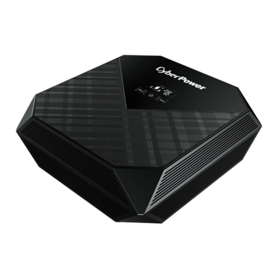
Summary of Contents for Cyber Power CPD1200EO12LCD
- Page 1 Hybrid Inverter CPD1200EO12LCD CPD2200EO24LCD User’s Manual...
-
Page 3: Table Of Contents
TABLE OF CONTENTS 1 IMPORTANT SAFETY INSTRUCTIONS…………………………..4 2 INSTALLATION……..………………………………………………..5 2-1 Unpacking………………………………………………………....5 2-2 Product Overview & Outlook…………………………………………..5 2-3 Power Requirements of Your Equipment…...………………………..7 2-4 Hardware Installation Guide……..…………………………………….7 3 DEFINITIONS FOR ILLUMINATED LCD INDICATORS…..10 4 OPERATION & CONFIGURATION……………………………….13 Power On/Off..……………………………………………………………...13 Function Setup……...…………………….…...………………....13 Audible Alarm……………………….…...……………………....13 Function Setup Guide……….…..……………………………....14 5 TROUBLESHOOTING……………………………………………..19... -
Page 4: Important Safety Instructions
1 IMPORTANT SAFETY INSTRUCTIONS (SAVE THESE INSTRUCTIONS) Before attempting to unpack, install, or operate the product, please read and follow all instructions carefully. CAUTION! To prevent the risk of fire or electric shock, install in a temperature and humidity controlled indoor area free of conductive contaminants. -
Page 5: Installation
2 INSTALLATION 2-1 Unpacking Inspect the product upon receipt. The box should contain the following: (a) This product; (b) User Manual; (c) Input Power Cord; (d) Temperature Sensor Hybrid Inverter User Manual Input Power Cord Temperature Sensor 2-2 Product Overview & Outlook CyberPower Solar Hybrid Inverter System converts renewable solar energy from panels into usable AC and store excess power in batteries as backup power during blackout and emergencies. - Page 6 CPD1200EO12LCD/CPD2200EO24LCD 1. Multifunction LCD Readout 2. Power On/off Switch 3. Function Buttons 4. AC Inlet 5. DC Input Cable(Red ”+”) 6. DC Input Cable(Black ”-”) 7. PV Input Terminals 8. Temperature Detection Port 9. AC Outlet Application Diagram...
-
Page 7: Power Requirements Of Your Equipment
2-3 Power Requirements of Your Equipment Ensure that the equipment plugged into the AC outlet does not exceed the product’s rated capacity (1200VA/900W for CPD1200EO12LCD, 2200VA/1600W for CPD2200EO24LCD). If rated unit capacities are exceeded, an overload condition may occur and cause the unit to shut down or the circuit breaker trip. - Page 8 Multiple Batteries Connection – in Parallel Connect multiple batteries in parallel can increase total battery capacity but still keep terminal voltage as single battery voltage. Step 2 Connect the Temperature Sensor Connect the temperature sensor to the unit’s RJ11 port. Put the sensor close to batteries so that the unit can detect the ambient temperature and control the utility charger with compensation.
- Page 9 Model PV Charging Current Wire Gauge CPD1200EO12LCD 10AWG CPD2200EO24LCD 10AWG Connect the cables from PV module to the unit’s PV input terminals. Please check the polarity before connection. For more information about PV Module Selection, please refer to the APPENDIX section.
-
Page 10: Definitions For Illuminated Lcd Indicators
3 DEFINITIONS FOR ILLUMINATED LCD INDICATORS LCD Display The left half of the LCD screen displays the energy flow direction and the status of the Power Inverter. The right half of the LCD screen displays the input, output, and battery information. Icon Description Normal Mode (Power On) - Page 11 Overload This icon appears and an alarm sounds to indicate the outlet is overloaded. Mute This icon appears whenever the unit is in silent mode. However, when there is a problem with the unit, the alarm will still beep even in silent mode.
- Page 12 Line Mode1 The Power Inverter is turned on and AC input power is normal. It supplies power to the load (connected equipment). Line Mode2 The Power Inverter is turned on and AC input power is normal. It supplies power to the load (connected equipment) and PV power charges the battery in the meantime.
-
Page 13: Operation & Configuration
4 OPERATION & CONFIGURATION Power On/Off Power On: Press the POWER button to turn on the unit. Power Off: Press the POWER button again to turn off the unit. Function Setup Press the SETUP button for 4 seconds to access the setup mode’s 17 functions: Audible Alarm, Input Voltage Range, Temperature Detection, Output Source Priority, Charging Source Priority, PV to Utility Transfer Voltage, Utility to PV Transfer Voltage, Total Max. -
Page 14: Function Setup Guide
Function Setup Guide Function Options Default Description Page 1 - Audible Alarm If Off is selected, the unit will mute alarms and the Mute icon will appear on the LCD display. Page 2 – Input Voltage Range Hi (Wide): For connected equipment (90-280Vac) that are less sensitive to the fluctuation of voltage range,... - Page 15 life. Page 4 - Output Source Priority Utility first U (Utility) U(Utility) Utility as first priority supplies P (PV) power to loads. When utility is not available, solar and battery will supply power to loads. PV first Solar as first priority supplies power to loads.
- Page 16 1200VA: In PV first condition, battery CPD1200EO12LCD: Page 6 - PV to Utility Transfer 11.5V may work with PV to supply 11.0/11.3/11.5/11.8/12. Voltage power to the loads, and 0/12.3/12.5/12.8V/ 2200VA: battery voltage will gradually 23.0V decrease. When battery...
- Page 17 Recommended setting: 10A for 100Ah battery 15A for 150Ah battery 20A for 200Ah battery Page 10 – Auto Restart Voltage When the utility power CPD1200EO12LCD: comes back and starts to Any/10.5/11.0//11.5/12 charge the battery, the .0/12.5/13.0/FUL/ESC Power Inverter will auto...
- Page 18 User can reset the value of Page 15 - Reset kwh from PV kwh from PV. Page 16 – Back to Default Select Yes to restore the factory default settings. Page 17 – Return to Status Press the Setup button to go Display back to the status display.
-
Page 19: Troubleshooting
5 TROUBLESHOOTING Problem Possible Cause Solution The unit is not connected to an The unit must be connected to a AC wall outlet. 220/230V outlet. The product will not turn on. The battery is worn out. Replace the batteries. Mechanical problem. Contact CyberPower Systems. - Page 20 Fault Code Table Fault Code Event Audible Alarm Overload Rapid beeping every 1/2 second High Temperature Beep every second PV Voltage High Beep every second PV Current High Beep every second PV Charger NTC Disconnect Beep every second Output Voltage High Constant tone Output Short Constant tone...
-
Page 21: Technical Specifications
6 TECHNICAL SPECIFICATIONS Model CPD1200EO12LCD CPD2200EO24LCD Power Rating (VA/Watt) 1200VA/900W 2200VA/1600W Input Narrow Mode: 170 - 280Vac Input Voltage Range Wide Mode: 90 - 280Vac Input Frequency 50/60Hz (Auto-sensing) Output Output Voltage 230Vac Output Frequency 50/60Hz Outlet Type (1) UN... -
Page 22: Appendix Pv Module Selection
If one PV module cannot meet this requirement, connect multiple PV modules in series to increase the total voltage. Example for CPD1200EO12LCD After considering Voc of PV module not exceeds 40VDC and Max. Vmp within 15~18VDC, we can choose PV module with below specification. - Page 23 CAUTION! Ensure that Open Circuit Voltage (Voc) of PV modules not exceeds 40V for CPD1200EO12LCD and 55V for CPD2200EO24LCD, or else the product may be damaged. If PV voltage or current is out of normal range, the unit will stop solar charging and send a warning code.
Need help?
Do you have a question about the CPD1200EO12LCD and is the answer not in the manual?
Questions and answers