Lantronix XPress DR+ User Manual
Industrial device server
Hide thumbs
Also See for XPress DR+:
- User manual (116 pages) ,
- Quick connect (2 pages) ,
- User manual (26 pages)

Related Manuals for Lantronix XPress DR+


Summary of Contents for Lantronix XPress DR+
- Page 1 ® XPress™ DR+ Industrial Device Server User Guide Part Number 900-778-R Revision D July 2022...
- Page 2 Technical Support Online: www.lantronix.com/support Sales Offices For a current list of our domestic and international sales offices, go to the Lantronix web site at www.lantronix.com/about/contact Disclaimer & Revisions Operation of this equipment in a residential area is likely to cause interference, in which case the user, at his or her own expense, will be required to take whatever measures may be required to correct the interference.
- Page 3 Changes or modifications to this device not explicitly approved by Lantronix will void the user's authority to operate this device. The information in this guide may change without notice. The manufacturer assumes no responsibility for any errors that may appear in this guide.
-
Page 4: Table Of Contents
Table of Contents List of Figures _____________________________________________________________ 7 List of Tables _____________________________________________________________ 8 1: Using This Guide Purpose and Audience ______________________________________________________ 9 Summary of Chapters ______________________________________________________ 9 Additional Documentation___________________________________________________ 10 2: Introduction Industrial Automation Protocols ______________________________________________ 12 Network Protocols (Serial Tunneling) __________________________________________ 13 XPress DR+ Application Examples ___________________________________________ 14 Addresses and Port Numbers _______________________________________________ 15 Configuration Methods _____________________________________________________ 16... - Page 5 Table of Contents Channel Configuration _____________________________________________________ 38 Applying Settings _________________________________________________________ 46 Applying Factory Defaults___________________________________________________ 46 6: Configuration Using Telnet/Serial Port (Setup Mode) Accessing Setup Mode _____________________________________________________ 47 Exiting Setup Mode _______________________________________________________ 49 7: Setup Mode: Server Configuration Server Configuration (Option 0) ______________________________________________ 50 8: Setup Mode: Channel Configuration Channel 1 (Option 1) and Channel 2 (Option 2) __________________________________ 53 Baudrate ________________________________________________________________ 53...
- Page 6 Table of Contents Troubleshooting Problems and Error Messages _______________________________________________ 80 DHCP __________________________________________________________________ 87 AutoIP __________________________________________________________________ 87 BOOTP _________________________________________________________________ 88 ARP and Telnet __________________________________________________________ 88 Converting Binary to Hexadecimal ____________________________________________ 89 RoHS, REACH and WEEE Compliance Statement _______________________________ 92 XPress™ DR+ Industrial Device Server User Guide...
-
Page 7: List Of Figures
Figure 3-4. Screw Terminal Ports _____________________________________________ 21 Figure 3-5. Termination Resistor for 2-Wire Connection ___________________________ 21 Figure 3-6. Lantronix P/N 500-103-R RJ45-DB9F Serial Cable Pinout ________________ 22 Figure 3-7. Multi-Drop Ethernet Connections ____________________________________ 23 Figure 3-8. Reset Switch ___________________________________________________ 24 Figure 3-9. -
Page 8: List Of Tables
List of Tables Table 3-1. RJ45 Serial Connector Pinouts ______________________________________ 20 Table 3-2. Serial Screw Terminal Pinout for RS-422 (4-Wire) _______________________ 20 Table 3-3. Serial Screw Terminal Pinout for RS-485 (2-Wire) _______________________ 20 Table 3-4. Ethernet Interface Signals __________________________________________ 22 Table 3-5.Typical RJ45 Connector (View from Connector End) ______________________ 23 Table 3-6. -
Page 9: 1: Using This Guide
This user guide describes and provides the information needed to configure, use, and update the Lantronix® XPress™ DR+ industrial device server. These device servers are members of the XPress family that work with Industrial Automation Protocols (IAP). It is for system administrators and those responsible for installing and maintaining these device servers. -
Page 10: Additional Documentation
Start and Com Port Redirector Online Help DeviceInstaller Online Help Provides information on using the Lantronix DeviceInstaller™ application to locate Lantronix devices on the network and configure IP addresses. Live tutorials on the Explain and demonstrate assigning an IP address and setting up the unit and the Redirector. -
Page 11: 2: Introduction
2: Introduction The Lantronix XPress DR+ industrial device server is a robust, feature-rich, and cost-effective way to network-enable equipment in an industrial automation environment. The XPress DR+ provides two serial ports, two switched Ethernet ports, a wide power input range, and expanded environmental specifications, making it an ideal solution for connecting multiple asynchronous RS-232, RS-422, or RS-485 serial devices to an Ethernet network. -
Page 12: Industrial Automation Protocols
For information about using any of the industrial communication protocols, find the protocol firmware files and the specific protocol guides at the Lantronix website at www.lantronix.com/support/downloads.html. XPress™ DR+ Industrial Device Server User Guide... -
Page 13: Network Protocols (Serial Tunneling)
UDP datagram is supported in the Standard Tunnel Protocol. XPress DR+ comes loaded with Standard Tunnel Protocol. Standard Tunneling is a serial communications protocol used by most Lantronix device servers. You can configure it to Ethernet-enable most serial devices such as barcode scanners, weigh scales, operator panels, data access devices, alphanumeric displays, and thousands of intelligent serial devices. -
Page 14: Xpress Dr+ Application Examples
2: Introduction XPress DR+ Application Examples Using a method called serial tunneling, the XPress DR+ encapsulates serial data into packets and transports them over Ethernet. Using two XPress DR+ units, connected by a network, you can extend virtual serial connections across a facility or around the world. Figure 2-2. -
Page 15: Addresses And Port Numbers
2: Introduction Figure 2-3. Example of Cascading Multiple XPress DR+ Units Addresses and Port Numbers Hardware Address The hardware address is also referred to as the Ethernet address or MAC address. Take note of the unit’s hardware address (also known as the Ethernet or MAC address). It is on the product label (see Product Information Label). -
Page 16: Configuration Methods
2: Introduction Port Numbers Every TCP connection and every UDP datagram is defined by a destination IP address and a port number. For example, a Telnet application commonly uses port number 23. A port number is similar to an extension on a phone system. You can associate the unit's serial channel (port) with a specific TCP/UDP port number. -
Page 17: 3: Installation And Hardware
The following diagram shows the basic connectivity of an XPress DR+ to the network and a serial device. The Lantronix-supplied part number 500-103-R serial cable can be used on the RJ45 RS- 232 serial ports to connect the XPress DR+ to a PC or to a serial device that has a DB9M RS-232 DTE interface. -
Page 18: Figure 3-1. Typical Configuration
3: Installation and Hardware Figure 3-1. Typical Configuration 1. Connect a serial device to your XPress DR+. (See for cable and Serial Interface connector specifications.) 2. Connect an Ethernet cable to the Ethernet port. (See Ethernet Interface.) 3. Supply power to your XPress DR+ using a 9-30 VDC or 9-24 VAC (2.3W maximum) source. -
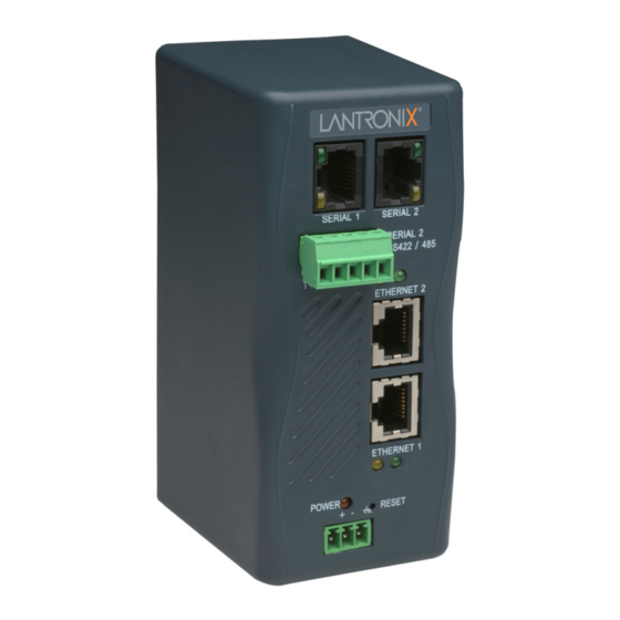
Page 19: Xpress Dr+ Front Panel
3: Installation and Hardware XPress DR+ Front Panel The following figure illustrates the screw terminal connector and other components of the XPress DR+. Figure 3-2. Front of XPress DR+ Serial Interface The XPress DR+ supports RS-232 via RJ45 connectors. It also supports RS-422/485 via screw terminals (Serial Port 2 only). -
Page 20: Figure 3-3. Rj45 Connector - Front View
3: Installation and Hardware Table 3-1. RJ45 Serial Connector Pinouts Direction Name Function Output from DR+ Ready To Send Output from DR+ Data Terminal Ready Output from DR+ Transmitted Data Ground Signal Ground Ground Signal Ground Input to DR+ Received Data Input to DR+ Data Set Ready Input to DR+... -
Page 21: Figure 3-4. Screw Terminal Ports
3: Installation and Hardware Figure 3-4. Screw Terminal Ports Note: Termination resistors (R = 120 Ohm) are used to match impedance of a node to the impedance of the transmission (TX) line. Termination resistors should be placed only at the extreme ends of the data line, and no more than two terminations should be placed in any single segment of an RS-485 network. -
Page 22: Ethernet Interface
PC Com port to the XPress DR+ serial port. This cable is pinned to provide full serial line control to an RS-232 DTE device. Lantronix offers a comprehensive list of cables and adapters to simplify device connectivity to the XPress DR+ unit. See... -
Page 23: Power Requirements
3: Installation and Hardware The next drawing shows a typical RJ45 connector. The color is not standard but very typical of an Ethernet patch cable. Pin 1 is located at the top of the connector (orange + white). The view is from the end of the connector. -
Page 24: Reset Switch
3: Installation and Hardware Reset Switch The XPress DR+ includes a hardware reset switch located in the small hole above the power connector. Pressing the reset switch causes a hardware reboot of the XPress DR+. The hardware reset does not reset or change the configuration of the XPress DR+. Figure 3-8. -
Page 25: Leds
3: Installation and Hardware LEDs Figure 3-9. LEDs on the XPress DR+ RXD Activity LED Power/Diagnostic LED Ethernet Link LEDs Table 3-6. XPress DR+ LED Functions Status Meaning Serial port - TXD LED (Yellow) No data being transmitted from XPress DR+ Blinking Data being transmitted from XPress DR+ Serial port - RXD LED (Green) -
Page 26: Dimensions
3: Installation and Hardware Dimensions The following drawing shows the dimensions of the XPress DR+. Figure 3-10. Dimensions Wall Mount Bracket Included with the XPress DR+ is an accessory DIN-rail wall mount bracket that makes it very easy to mount the unit in locations where a DIN-rail is not available. Figure 3-11. -
Page 27: Product Information Label
3: Installation and Hardware Product Information Label The product information label on the underside of the unit contains important information about your specific unit: Product Part Number Product Revision Manufacturing Date Code Country of Manufacturing Origin Serial Number (which is also the product MAC address) ... -
Page 28: 4: Using Deviceinstaller
Note: If the unit already has an IP address (e.g., DHCP has assigned an IP address), click the Search icon and select the unit from the list of Lantronix device servers on the local network. 2. Click the Assign IP icon. -
Page 29: Accessing The Xpress Dr+ Using The Deviceinstaller Application
Make note of the MAC address. It may be needed to perform various functions in the DeviceInstaller application. 1. Click Start > All Programs > Lantronix > DeviceInstaller 4.4 > DeviceInstaller. When DeviceInstaller starts, it will perform a network device search. - Page 30 4: Using DeviceInstaller Setting Description Comments Configurable field. Information about the XPress DR+. Double-click the field, type in the value, and press Enter to complete. This description or comment is not visible on other PCs or laptops using DeviceInstaller. Device Family Non-configurable field.
- Page 31 4: Using DeviceInstaller Setting Description Supports Email Non-configurable field. Displays False. Triggers Supports AES Data Non-configurable field. Displays False. Stream Supports 485 Non-configurable field. Displays True. XPress DR+ supports the RS-485 protocol. Supports 921K Non-configurable field. Displays False. XPress DR+ supports baud rates up to Baudrate a maximum of 230 Kbaud.
-
Page 32: 5: Configuration Using Web Manager
The unit performs a reset after you change and store the configuration. In this chapter, we describe how to configure the XPress DR+ using Web Manager, a Lantronix browser-based configuration tool. Web Manager refers to our web-based configuration manager for the device server product. -
Page 33: Figure 5-1. Lantronix Web Manager
16-character password. See Security Settings (Option 6) on page The Web-Manager displays. Figure 5-1. Lantronix Web Manager 00-80-A3-8E-3C-7A The main menu is in the left pane of the Web Manager window. XPress™ DR+ Industrial Device Server User Guide... -
Page 34: Network Configuration
5: Configuration Using Web Manager Network Configuration The unit’s network values display when you select Network from the main menu. The following sections describe the configurable parameters on the Network Settings page. Figure 5-2. Network Settings Automatic IP Address Configuration An IP address can be assigned automatically. - Page 35 5: Configuration Using Web Manager DHCP Host Name Enter the name of the host on the network providing the IP address. Note: Disabling BOOTP, DHCP, and AutoIP (all three checkboxes) is not advised as the only available IP assignment method will then be ARP or the serial port. 5.
-
Page 36: Server Configuration
5: Configuration Using Web Manager Server Configuration The unit’s server values display when you select Server from the main menu. The following sections describe the configurable parameters on the Server Settings page. Figure 5-3. Server Settings To configure the unit's device server settings: On the main menu, click Server. -
Page 37: Host List Configuration
5: Configuration Using Web Manager Retype Password Re-enter the password required for Telnet configuration and Web Manager access. Advanced ARP Cache Timeout When the unit communicates with another device on the network, it adds (secs) an entry into its ARP table. ARP Cache timeout defines the number of seconds (0-600) before it refreshes this table. -
Page 38: Channel Configuration
5: Configuration Using Web Manager Figure 5-4. Hostlist Settings 2. Enter or modify the following fields: Retry Settings Retry Counter Enter the value for the number of times the XPress DR+ should attempt to retry connecting to the host list. The default setting is 3. Retry Timeout Enter the duration (in milliseconds) the XPress DR+ should abandon attempting a connection to the host list. -
Page 39: Figure 5-5. Channel Serial Settings
5: Configuration Using Web Manager Serial Settings To configure the channel’s serial settings: On the main menu, click Serial Settings (below Channel 1) to display the Serial Settings window. Figure 5-5. Channel Serial Settings 2. In the available fields, enter the following information: Channel 1 Disable Serial Port When selected, disables communication through the serial port. - Page 40 5: Configuration Using Web Manager Flow Control Flow control manages data flow between devices in a network to ensure the data is processed efficiently. Too much data arriving before a device is prepared to manage it causes lost or retransmitted data. None is the default setting.
- Page 41 5: Configuration Using Web Manager With Active Connect Select Yes to clear the output buffer with a connection that is initiated from the device to the network. The default setting is No. With Passive Connect Select Yes to clear the output buffer with a connection initiated from the network to the device.
-
Page 42: Figure 5-6. Tcp Connection Settings
5: Configuration Using Web Manager Figure 5-6. TCP Connection Settings 2. In the available fields, enter or modify the following information: Connect Protocol Protocol From the drop-down menu, select TCP. Connect Mode: Passive Connection Accept Incoming Select Yes to accept incoming connections. The default setting is Yes. - Page 43 5: Configuration Using Web Manager Connect Mode: Active Connection Active Connect Select None (default) to disable Active Connect. Otherwise, select the connection type from the drop-down list: With Any Character: Attempts to connect when any character is received from the serial port. With Active Mdm Ctrl In: Accepts external connection requests ...
- Page 44 5: Configuration Using Web Manager Use Hostlist If this option is set to Yes, the device server scrolls through the host list until it connects to a device listed in the host list table. Once it connects, the unit stops trying to connect to any others. If this connection fails, the unit continues to scroll through the table until it connects to another IP in the host list.
-
Page 45: Figure 5-7. Udp Connection Settings
5: Configuration Using Web Manager Figure 5-7. UDP Connection Settings Connect Protocol Protocol Select UDP from the drop-down menu. Datagram Mode Datagram Type Configures the remote IP or network broadcast address and the remote port. Enter 01 for directed or broadcast UDP. The default setting is 00. -
Page 46: Applying Settings
5: Configuration Using Web Manager Note: Lantronix Tech Support supports Datagram type 01. Datagram Type FD is for OEM use. 3. When finished, click the OK button. 4. To save and reboot, click Apply Settings on the main menu. Applying Settings 1. -
Page 47: 6: Configuration Using Telnet/Serial Port (Setup Mode)
The series of prompts at which you enter configuration settings is called Setup Mode. Note: Detailed information about other setup methods is available from Lantronix Technical Support (http://www.lantronix.com/support). The unit’s configuration is stored in nonvolatile memory and is retained without power. -
Page 48: Figure 6-1. Mac Address
1. Connect a console terminal (VT100) or PC running a terminal emulation program from port 1 with the Lantronix supplied P/N: 500-103-R RJ45-to-DB9F serial cable. The default serial port settings are 9600 baud, 8 bits, no parity, 1-stop bit, no-flow control. -
Page 49: Exiting Setup Mode
6: Configuration Using Telnet/Serial Port (Setup Mode) Exiting Setup Mode To exit setup mode, you have two options: To save all changes and reboot the device, select option 9 Save and exit from the Change Setup menu. All values are stored in nonvolatile memory. To exit the configuration mode without saving any changes or rebooting. -
Page 50: 7: Setup Mode: Server Configuration
7: Setup Mode: Server Configuration This chapter explains how to configure the network settings for the XPress DR+ device server. Note: Current values display in parentheses. Server Configuration (Option 0) You can configure the unit’s basic network parameters when you select Server configuration (option 0). -
Page 51: Table 7-2. Standard Ip Network Netmasks
7: Setup Mode: Server Configuration Netmask: Number of Bits for Host Par A netmask defines the number of bits taken from the IP address that are assigned for the host part. Netmask: Number of Bits for Host Part (0=default) (0) _ Note: Class A: 24 bits;... - Page 52 The hostname is myxport, and the host is located within the domain lantronix.com. The option to enable DHCP FQDN becomes available if DHCP is enabled. Enable DHCP FQDN option : (N) XPress™ DR+ Industrial Device Server User Guide...
-
Page 53: 8: Setup Mode: Channel Configuration
8: Setup Mode: Channel Configuration This chapter explains how to configure a serial port. Notes: Current values display in parenthesis. You must enter some values in hexadecimal notation. (See E: Binary to Hexadecimal Conversions.) Channel 1 (Option 1) and Channel 2 (Option 2) Note: Channel 1 and Channel 2 have the same defaults except for the port number (10001 for Channel 1 and 10002 for Channel 2). -
Page 54: Interface (I/F) Mode
8: Setup Mode: Channel Configuration Interface (I/F) Mode The Interface (I/F) Mode is a bit-coded byte entered in hexadecimal notation. The default setting is 4C. I/F Mode (4C) ? _ The following table displays available I/F Mode options. Note: All bit positions in the table that are blank represent “don’t care” bits for that particular option, which can be set to either a 0 or 1 value. -
Page 55: Flow
8: Setup Mode: Channel Configuration Flow Flow control sets the local handshaking method for stopping serial input/output. The default setting is 00. Flow (00) ? _ Use the following table to select flow control options: Table 8-3. Flow Control Options Flow Control Option No flow control XON/XOFF flow control... -
Page 56: Connect Mode
8: Setup Mode: Channel Configuration Connect Mode Connect Mode defines how the unit makes a connection, and how it reacts to incoming connections over the network. ConnectMode (C0) ? _ Enter Connect Mode options in hexadecimal notation. The default setting is C0. Note: All bit positions in the table that are blank represent “don’t care”... - Page 57 8: Setup Mode: Channel Configuration Connect Mode Option Modem Response Only (Numeric) Modem Response Only (Verbose) a) Incoming Connection Never Accept Incoming Rejects all external connection attempts. Accept with active Modem Accepts external connection requests only when the Modem Control In Control In is asserted.
-
Page 58: Table 8-6 Manual Connection Address Example
Connects to 129.1.2.5, port 1234 C28.10/12 Connects to 129.1.28.10, port 12 C0.0.0.0/0 Enters Monitor Mode Tries to connect to the Lantronix web server if the Cwww.lantronix.com/80 <hostname:domain> (www.lantronix.com) is configured in the DNS server database Autostart (Automatic If you enable Autostart, the unit automatically connects to the... -
Page 59: Figure 8-2 Hostlist Option
3. After completing the host list, repeat the previous step if necessary to edit the host list again. 4. For Retrycounter, enter the number of times the Lantronix unit should try to make a good network connection to a host list entry that it has successfully ARPed. The range is 1- 15, with the default set to 3. - Page 60 8: Setup Mode: Channel Configuration d) Datagram Type Directed UDP When selecting this option, you are prompted for the Datagram type. Enter 01 for directed or broadcast UDP. When the UDP option is in effect, the unit never attempts to initiate a TCP connection because it uses UDP datagrams to send and receive data.
-
Page 61: Table 8-7 Modem Mode Messages
8: Setup Mode: Channel Configuration Table 8-7 Modem Mode Messages Message Meaning Full Verbose Command was executed without error. CONNECT A network connection has been established. NO CARRIER A network connection has been closed. RING n.n.n.n. A remote device, having IP address n.n.n.n, is connecting to this device. Numeric Response Connected Ring... -
Page 62: Send The Escape Sequence (+++) In Modem Mode
8: Setup Mode: Channel Configuration The character string ATH is received, terminated with a carriage return. The unit responds affirmatively according to the selected echo/response mode and drops the network connection. The serial interface reverts to accepting command strings. If this sequence is not followed, the unit remains in data transfer mode. -
Page 63: Show Ip Address After Ring
8: Setup Mode: Channel Configuration Show IP Address After Ring Show IP addr after ‘RING’ (Y) ? Disable or enable the XPress DR+ device’s ability to show the IP address after RING in Modem Mode. The default is Y (Yes), to show the IP address. Auto Increment Source Port Auto increment source port (N)? _ Y (Yes) auto increments the source port. -
Page 64: Flush Mode (Buffer Flushing)
8: Setup Mode: Channel Configuration Table 8-9 Disconnect Mode Options Disconnect Mode Option Disconnect when Modem Control In is not asserted ( Ignore Modem Control In Telnet Com Port Cntrl and terminal type setup Channel (port) password Hard disconnect Disable hard disconnect State LED off with connection Disconnect with EOT (^D) (1) The Telnet Com Port Control feature is used in conjunction with Com Port Redirector. -
Page 65: Pack Control
8: Setup Mode: Channel Configuration Function Clear when the network connection to or from the device is disconnected Output Buffer (Network to Serial) Clear with a connection initiated from the device to the network Clear with a connection initiated from the network to the device Clear when the network connection to or from the device is disconnected Alternate Packing Algorithm (Pack Control) Enable... -
Page 66: Disconntime (Inactivity Timeout)
8: Setup Mode: Channel Configuration Packing Interval Packing Interval defines how long the unit should wait before sending accumulated characters. This wait period is between successive network segments containing data. For alternate packing, the default interval is 12 ms. Trailing Characters In some applications, CRC, Checksum, or other trailing characters follow the end-of-sequence character;... -
Page 67: Telnet Terminal Type
8: Setup Mode: Channel Configuration Telnet Terminal Type This parameter displays only if you enabled the terminal type option in Disconnect Mode. When enabled, you can use the terminal name for the Telnet terminal type. Enter only one name. Terminal name ()? With terminal type option enabled, the unit also reacts to the EOR (end of record) and binary options, useful for applications like terminal emulation to IBM hosts. -
Page 68: 9: Setup Mode: Advanced Settings
9: Setup Mode: Advanced Settings Expert Settings (Option 5) Note: You can change these settings using Telnet or serial connections only, not on the Web Manager. Caution: Changing the expert settings can drastically affect the performance and access to the product. These settings should only be changed by an experienced network administrator. -
Page 69: Security Settings (Option 6)
9: Setup Mode: Advanced Settings HTTP Port Number This option allows the configuration of the web server port number. The valid range is 1-65535. The default HTTP port number is 80. HTTP Port Number: (80) ? _ MTU Size The Maximum Transmission Unit (MTU) is the largest physical packet size a network can transmit for TCP and UDP. - Page 70 9: Setup Mode: Advanced Settings Disable Port 77FEh (N)? 77FEh Access Mode (0=Read & Write, 1=Read Only): (0)? Disable Web Server (N)? Disable Web Setup (N)? Disable ECHO ports (Y)? Enable Enhanced Password (N)? Disable SNMP This setting allows you to disable the SNMP protocol on the unit for security reasons. The default setting is N (No).
- Page 71 9: Setup Mode: Advanced Settings Disable Port 77FE (Hex) Note: If you choose to disable this option, keep in mind that disabling both Telnet Setup and Port 77FE will prevent users from accessing Setup Mode from the network. Port 77FE is a setting that allows DeviceInstaller, Web Manager, and custom programs to configure the unit remotely.
-
Page 72: Default Settings (Option 7)
9: Setup Mode: Advanced Settings Enable Enhanced Password The Enhanced Password setting allows you to set a password of up to 16 characters for protecting Telnet and Web Page access. We recommend that you select the Y (Yes) option and enable the enhanced password setting. - Page 73 9: Setup Mode: Advanced Settings Security Settings Disable SNMP SNMP community name public Disable Telnet setup Disable TFTP Firmware Update Disable Port 77FEh Disable Web Server Disable Web Setup Disable ECHO ports Enable Enhanced password Enable Telnet Authentication XPress™ DR+ Industrial Device Server User Guide...
-
Page 74: 10: Firmware Upgrades
DeviceInstaller (the preferred way), using TFTP, or using the serial port. You can also update the unit's internal web interface (*.COB) using TFTP or DeviceInstaller. Here are typical names for those files. Check the Lantronix web site for the latest versions and release notes. -
Page 75: Figure 10-1. Tftp Window
10: Firmware Upgrades Figure 10-1. TFTP Window After the firmware has been loaded and stored, which takes approximately 8 seconds to complete, the unit performs a power reset. Using TFTP: Command Line Interface To download new firmware from a computer: Enter the following from a TFTP command line interface: tftp –i <ip address>... - Page 76 10: Firmware Upgrades 3. For Port on PC, enter the COM port on the PC that is connected to the serial port of the Lantronix unit. 4. For Device Model, be sure the appropriate XPress DR+ device displays. 5. For Firmware File, click the Browse button and go to the location where the firmware file resides.
-
Page 77: 11: Monitor Mode
2. Type M (upper case). A 0> prompt indicates that you have successfully entered Monitor Mode. Figure 11-1. Accessing Monitor Mode *** Lantronix XPress DR+ Industrial Device Server *** MAC address 0080A38E3C7A Software version V6.11.0.4 (160916) Press Enter for Setup Mode Monitor Mode Commands The following commands are available in Monitor Mode. -
Page 78: Table 11-1. Monitor Mode Commands
11: Monitor Mode Table 11-1. Monitor Mode Commands Command Command Name Function ARP Table Shows the unit’s ARP table entries. Set IP address, host bits, Example: gateway, and DNS co 192.168.0.10 8 192.168.0.1 10001 192.168.1.10 server IP with 192.168.0.10 = IP address of the XPress DR+ 8 = number of host bits 192.168.0.1 = gateway IP address 10001 = port number of the XPress DR+... -
Page 79: Table 11-2. Command Response Codes
11: Monitor Mode Command Command Name Function TCP Connection Table Shows all incoming and outgoing TCP connections. Query full firmware This command queries and displays full firmware version version in readable string format. Version Queries software header record (16 bytes) of unit VS x.x.x.x with IP address x.x.x.x. -
Page 80: 12: Troubleshooting
This chapter discusses how you can diagnose and fix errors quickly without having to contact a dealer or Lantronix. It helps to connect a terminal to the serial port while diagnosing an error to view summary messages that may display. When troubleshooting, always ensure that the physical connections (power cable, network cable, and serial cable) are secure. - Page 81 12: Troubleshooting Problem/Message Reason Solution The IP address you are trying to Confirm that your PC has an IP assign is not on your logical address and that it is in the subnet. same logical subnet that you are trying to assign to the device server.
- Page 82 12: Troubleshooting Problem/Message Reason Solution The device server appears to be If you are sure that the serial Use the Connect Mode option C0 for making a connection to set up correctly, but you are not port setting is correct, then you communicating with your device may not be connecting to the the device server from the...
- Page 83 12: Troubleshooting A. Technical Support Lantronix offers many resources to support our customers and products at http://www.lantronix.com/support. For instance, you can ask a question, find firmware downloads, access the FTP site and search through tutorials. At this site you can also find FAQs, bulletins, warranty information, extended support services and product documentation.
- Page 84 B. Technical Specifications Table B-1 XPress DR+ Specifications Category Description Lantronix DSTNI-EX 48 MHz clock Internal CPU Memory 256 KB SRAM Flash 2 MB Flash EEPROM 4 KB EEPROM Serial Interface 2 RJ45 RS-232 Serial Ports Baud rate selectable from 300 to 230 Kbaud...
- Page 85 B: Technical Specifications Category Description LEDs TX/RX activity per serial Link/Activity per Ethernet port Power/System OK Isolation 8 KV direct contact, 15 KV air discharge, ESD protection on all serial ports (IEC 1000-4- 2, IEC 61000-4-2) 2 K VAC / 2.8K VDC galvanic isolation between power input port to Ethernet ports (except chassis ground) 2 K VAC / 2.8K VDC galvanic isolation between power input port to serial ports Transient Voltage protection and ESD with max non-repetitive surge current 800 A...
- Page 86 C. Lantronix Cables and Adapters Table C-1 Lantronix Cables, Adapters, and Part Number Lantronix P/N Description Applications 500-103-R 6’ RJ45-to DB9F Included with XPress DR+ for setup or device connectivity. Connects the RJ45 RS-232 serial ports of XPress DR+ to a DB9M DTE interface of a PC or serial device.
-
Page 87: Dhcp
D. Alternative Methods of Assigning an IP Address Earlier chapters describe how to assign a static IP address using DeviceInstaller, Web- Manager, and Setup Mode (through a Telnet or serial connection). This section covers other methods for assigning an IP address over the network. DHCP The unit ships with a default IP address of 0.0.0.0, which automatically enables DHCP. -
Page 88: Bootp
D: Alternative Methods of Assigning an IP Address BOOTP Similar to DHCP, but for smaller networks. Automatically assigns the IP address for a specific duration of time. ARP and Telnet If the unit has no IP address, you can use Address Resolution Protocol (ARP). To assign a temporary IP address: 1. -
Page 89: Converting Binary To Hexadecimal
E. Binary to Hexadecimal Conversions Many of the unit’s configuration procedures require you to assemble a series of options (represented as bits) into a complete command (represented as a byte). The resulting binary value must be converted to a hexadecimal representation. Converting Binary to Hexadecimal Following are two simple ways to convert binary numbers to hexadecimal notation. - Page 90 E: Binary to Hexadecimal Conversions 4. Click Hex. The hexadecimal value displays. XPress™ DR+ Industrial Device Server User Guide...
- Page 91 Declaration of Conformity (According to ISO/IEC Guide 22 and BS 7514) Manufacturer’s Name & Address: Lantronix, 7535 Irvine Center Drive, Suite 100, Irvine, CA 92618 USA Declares that the following product: Product Name Model: XPress DR+ Industrial Device Server Description: 2-Port Industrial Device Server...
-
Page 92: Rohs, Reach And Weee Compliance Statement
Low Voltage Directive 72/23/EEC and the EMC Directive 89/336/EEC. RoHS, REACH and WEEE Compliance Statement Please visit http://www.lantronix.com/legal/rohs/ for Lantronix’s statement about RoHS, REACH and WEEE compliance. XPress™ DR+ Industrial Device Server User Guide...
Need help?
Do you have a question about the XPress DR+ and is the answer not in the manual?
Questions and answers