Lantronix XPress DR+ User Manual
Hide thumbs
Also See for XPress DR+:
- User manual (116 pages) ,
- Quick connect (2 pages) ,
- User manual (26 pages)
Table of Contents
Advertisement
Quick Links
Download this manual
See also:
User Manual
Advertisement
Table of Contents

Related Manuals for Lantronix XPress DR+


Summary of Contents for Lantronix XPress DR+
- Page 1 distributed by: XPress DR+ User Guide Part Number 900-422 Revision A March 2006...
- Page 2 Copyright & Trademark © 2006, Lantronix. All rights reserved. No part of the contents of this book may be transmitted or reproduced in any form or by any means without the written permission of Lantronix. Printed in the United States of America.
-
Page 3: Table Of Contents
Contents 1: Using This Guide Purpose and Audience________________________________________________ 9 Summary of Chapters ________________________________________________ 9 Additional Documentation ____________________________________________ 10 2: Introduction Product Description _________________________________________________ 11 Industrial Automation Protocols ________________________________________ 12 Network Protocols (Serial Tunneling)____________________________________ 13 Application Examples________________________________________________ 13 Addresses and Port Numbers _________________________________________ 15 Hardware Address ______________________________________________________ 15 IP Address ____________________________________________________________ 15 Port Numbers __________________________________________________________ 15... - Page 4 Contents Accessing the XPress DR+ Using DeviceInstaller __________________________ 27 Viewing the Current Configuration ______________________________________ 27 5: Configuration Using Web-Manager Accessing XPress DR+ Using DeviceInstaller _____________________________ 30 Network Configuration _______________________________________________ 31 Automatic IP Address Configuration ________________________________________ 32 Static IP Address Configuration ____________________________________________ 33 Server Configuration ________________________________________________ 33 Host List Configuration_______________________________________________ 35 Channel Configuration _______________________________________________ 36...
- Page 5 Contents d) Datagram Type ______________________________________________________ 56 e) Modem Mode ________________________________________________________ 56 Send the Escape Sequence (+++) in Modem Mode ________________________ 59 Auto Increment Source Port___________________________________________ 59 Remote IP Address _________________________________________________ 59 Remote Port_______________________________________________________ 59 DisConnMode _____________________________________________________ 59 Flush Mode (Buffer Flushing)__________________________________________ 60 Pack Control ______________________________________________________ 61 Packing Interval ________________________________________________________ 61 Trailing Characters ______________________________________________________ 61...
- Page 6 Monitor Mode Commands ________________________________________________ 71 12: Troubleshooting and Technical Support Problems and Error Messages ________________________________________ 73 Technical Support __________________________________________________ 76 A: Technical Specifications B: Lantronix Cables and Adapters C: Alternative Methods of Assigning an IP Address DHCP ________________________________________________________________ 80 AutoIP________________________________________________________________ 80 BOOTP_______________________________________________________________ 81...
- Page 7 Figure 3-10. Dimensions ..................24 Figure 3-11. Wall Mount Bracket................. 24 Figure 3-12. Product Label .................. 25 Figure 5-1. Lantronix Web-Manager ..............31 Figure 5-2. Network Settings ................32 Figure 5-3. Server Settings.................. 34 Figure 5-4. Hostlist Settings ................35 Figure 5-5.
- Page 8 Contents Table 8-10. Pack Control Options ............... 61 Table 10-1. Firmware Files.................. 68 Table 11-1. Monitor Mode Commands..............72 Table 12-1. Problems and Error Messages............73 XPress DR+ User Guide...
-
Page 9: 1: Using This Guide
1: Using This Guide Purpose and Audience This manual describes the XPress DR+, a device server that works with Industrial Automation Protocols. It is a member of the Lantronix family of XPress DR Device Servers. Summary of Chapters The remaining chapters in this guide include:... -
Page 10: Additional Documentation
Conversions hexadecimals. Compliance Information Warranty Additional Documentation The following guides are available on the product CD and the Lantronix web site (www.lantronix.com). XPress DR+ Quick Start Provides the steps for getting the XPress DR+ up and running. Com Port Redirector User Guide Provides information on using the Windows-based utility to create a virtual com port. -
Page 11: 2: Introduction
This chapter provides basic information about the XPress DR+. Product Description The Lantronix XPress DR+ Industrial Device Server is a robust, feature-rich, and cost effective way to network-enable equipment in an industrial automation environment. The XPress DR+ provides two serial ports, two switched Ethernet ports, a wide power input... -
Page 12: Industrial Automation Protocols
2: Introduction The XPress DR+ can connect devices using various methods of TCP/IP communications, for example, through a TCP data channel, using UDP datagrams, or though a Telnet connection. Communication can be established from the XPress DR+ to a host computer or another device or from a host computer or device to the XPress DR+. -
Page 13: Network Protocols (Serial Tunneling)
2: Introduction For information about using any of the industrial communication protocols, see the specific protocol guides on the software CD or the Lantronix web site. Protocol firmware files are also on the CD. Note: Please check the Lantronix web site for newer versions that may become available. -
Page 14: Figure 2-2. Example Of Serial Tunneling
2: Introduction Figure 2-2. Example of Serial Tunneling The internal two-port Ethernet switch allows the XPress DR+ to cascade connections from a single network drop to another Ethernet device or from one XPress DR+ to another and another, and so on. Figure 2-3. -
Page 15: Addresses And Port Numbers
The hardware address is also referred to as the Ethernet address or MAC address. The first three bytes of the Ethernet address are fixed and read 00-20-4A, identifying the unit as a Lantronix product. The fourth, fifth, and sixth bytes are unique numbers assigned to each unit. -
Page 16: 3: Installation And Hardware
The following diagram shows the basic connectivity of an XPress DR+ to the network and a serial device. The Lantronix supplied P/N: 500-103 serial cable can be used on the RJ45 RS232 serial ports to connect the XPress DR+ to a PC or to a serial device that has a DB9M RS232 DTE interface. -
Page 17: Front Panel Description
3: Installation and Hardware Figure 3-1. Typical Configuration 1. Connect a serial device to your XPress DR+. (See Serial Interface on page 18 for cable and connector specifications.) 2. Connect an Ethernet cable to the Ethernet port. (See Ethernet Interface on page 20.) 3. -
Page 18: Serial Interface
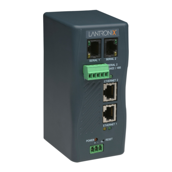
3: Installation and Hardware Figure 3-2. Front Panel Layout Serial Interface The XPress-DR+ supports RS-232 via RJ45 connectors. It also supports RS-422/485 via screw terminals (Serial Port 2 only). Note: Serial Port 2 supports RS232, RS422, and RS485, but only one mode at a time. -
Page 19: Screw Terminal Serial Connectors
3: Installation and Hardware Screw Terminal Serial Connectors Table 3-2. Serial Screw Terminal Pinout for RS422 (4-Wire) Direction Name Function Output Transmit Data + Output Transmit Data - Ground Signal Ground Input Received Data + Input Received Data - Table 3-3. Serial Screw Terminal Pinout for RS485 (2-Wire) Direction Name Function... -
Page 20: 9-Pin Rs-232 To Serial Rj45 Cable (P/N 500-103)
PC Com port to the XPress DR+ serial port. This cable is pinned to provide full serial line control to an RS232 DTE device. Lantronix offers a comprehensive list of cables and adapters to simplify device connectivity to the XPress DR+. -
Page 21: Multi-Drop Ethernet Connections
3: Installation and Hardware Table 3-4. Ethernet Interface Signals Direction Name Function Transmit Data + Transmit Data - Differential Ethernet Receive Data + Differential Ethernet Receive Data - The next drawing shows a typical RJ45 connector. The color is not standard but very typical of an Ethernet patch cable. -
Page 22: Power Requirements
3: Installation and Hardware Power Requirements As with most industrial automation devices, the XPress DR+ does not ship with a power supply. Its flexible power input circuit allows the product to be powered by any 9-30 VDC or 9-24 VAC power supply that can provide the 2.3-Watt maximum required by the XPress DR+. -
Page 23: Leds
3: Installation and Hardware LEDs Figure 3-9. LEDs RXD Activity LED TXD Activity LED Ethernet Link LED Power/Diagnostic LED Ethernet Activity LED Table 3-6. LED Functions Meaning Serial port - TXD LED (Yellow) Off = No Transmit Data from XPress DR+ Blinking = Data being transmitted from XPress DR+ Serial port - RXD LED (Green) Off = No Received Data by XPress DR+... -
Page 24: Dimensions
3: Installation and Hardware Dimensions The following drawing shows the dimensions of the XPress DR+ Figure 3-10. Dimensions Wall Mount Bracket Included with the XPress DR+ is an accessory DIN-rail wall mount bracket that makes it very easy to mount the unit in locations where a DIN-rail is not available. Figure 3-11. -
Page 25: Product Information Label
3: Installation and Hardware Product Information Label The product information label on the underside of the unit contains important information about your specific unit: Bar code Serial number Product ID (name) Product description Hardware address (also referred to as Ethernet or MAC address) Your unit will have one similar to the one below. -
Page 26: 4: Using Deviceinstaller
This chapter covers the steps for getting the XPress DR+ device server online and viewing its current configuration. Note: For the latest firmware, release notes, and user documentation, go to the Lantronix web site (www.lantronix.com). Installing DeviceInstaller To install DeviceInstaller: 1. -
Page 27: Accessing The Xpress Dr+ Using Deviceinstaller
Note: If the unit already has an IP address (e.g., DHCP has assigned an IP address), click the Search icon and select the unit from the list of Lantronix device servers on the local network. 2. Click the Assign IP icon 3. - Page 28 4: Using DeviceInstaller Name Configurable field. A name that identifies the XPress DR+. Double-click the field, type in the value, and press Enter to complete. This name is not visible on other PCs or laptops using DeviceInstaller. Group Configurable field. A group name to categorize the XPress DR+.
- Page 29 4: Using DeviceInstaller DHCP Non-configurable field that displays only if the unit supports Dynamic IP. True indicates that the IP address can be assigned automatically by DHCP. BOOTP Non-configurable field that displays only if the unit supports Dynamic IP. True indicates that the IP address can be assigned automatically by BOOTP.
-
Page 30: 5: Configuration Using Web-Manager
In this chapter, we describe how to configure the XPress DR+ using Web-Manager, Lantronix’s browser-based configuration tool. (For information on using Setup Mode, our command line configuration interface, see 6: Configuration Using Telnet or Serial Port (Setup Mode). -
Page 31: Network Configuration
Note: Alternatively, to open Web-Manager, start your web browser and enter the IP address of the XPress DR+. Figure 5-1. Lantronix Web-Manager The main menu is in the left pane of the Web-Manager window. Network Configuration The unit’s network values display when you select Network from the main menu. The following sections describe the configurable parameters on the Network Settings page. -
Page 32: Automatic Ip Address Configuration
5: Configuration Using Web-Manager Figure 5-2. Network Settings Automatic IP Address Configuration An IP address can be assigned automatically. You then enter related network settings. To assign an IP address automatically: 1. On the main menu, click Network. 2. Select Obtain IP address automatically. 3. -
Page 33: Static Ip Address Configuration
5: Configuration Using Web-Manager 4. When you are finished, click the OK button. 5. To save and reboot, click Apply Settings on the main menu. Static IP Address Configuration You manually assign an IP address to the unit and enter related network settings. To assign an IP address manually: 1. -
Page 34: Figure 5-3. Server Settings
5: Configuration Using Web-Manager Figure 5-3. Server Settings To configure the unit's device server settings: 1. On the main menu, click Server. 2. Configure or modify the following fields: Server Configuration Telnet Password Enter the password required for Telnet access. Retype Password Re-enter the password required for Telnet access. -
Page 35: Host List Configuration
5: Configuration Using Web-Manager MTU Size The Maximum Transmission Unit (MTU) is the largest physical packet size a network can transmit for TCP and UDP. Enter between 512 and 1400 bytes. The default setting is 1400 bytes. 3. When you are finished, click the OK button. 4. -
Page 36: Channel Configuration
5: Configuration Using Web-Manager Retry Settings Retry Counter Enter the value for the number of times the XPress DR+ should attempt to retry connecting to the host list. The default setting is 3. Retry Timeout Enter the duration (in seconds) the XPress DR+ should abandon attempting a connection to the host list. -
Page 37: Figure 5-5. Channel Serial Settings
5: Configuration Using Web-Manager Figure 5-5. Channel Serial Settings 2. In the available fields, enter the following information: Channel 1 Disable Serial Port When selected, disables communication through the serial port. The serial port is enabled by default. Port Settings Protocol From the drop-down menu, select the protocol type for the selected channel. - Page 38 5: Configuration Using Web-Manager Pack Control Enable Packing Select to enable packing on the XPress DR+. Disabled by default. Two firmware-selectable packing algorithms define how and when packets are sent to the network. The standard algorithm is optimized for applications in which the unit is used in a local environment, allowing for very small delays for single characters, while keeping the packet count low.
-
Page 39: Connection Settings - Tcp
5: Configuration Using Web-Manager 4. To save and reboot, click Apply Settings on the main menu. Connection Settings - TCP To configure a channel’s TCP settings: 1. On the main menu, click Connection. The Connection Settings window for the channel displays. Figure 5-6. - Page 40 5: Configuration Using Web-Manager 2. In the available fields, enter or modify the following information: Connect Protocol Protocol From the drop-down menu, select TCP. Connect Mode: Passive Connection Accept Incoming Select Yes to accept incoming connections. The default setting is Yes. Password Required Determines whether a password is required for an incoming passive connection.
-
Page 41: Connection Settings - Udp
5: Configuration Using Web-Manager communication to the XPress DR+. Terminal Name This field is available for configuration only when Telnet Mode is set to Enable. Use the terminal name for the Telnet terminal type. Enter only one name. When this option is enabled, the unit also reacts to the end of record (EOR) and binary options, which can be used for applications such as terminal emulation to IBM hosts. -
Page 42: Figure 5-7. Udp Connection Settings
5: Configuration Using Web-Manager Figure 5-7. UDP Connection Settings Connect Protocol Protocol Select UDP from the drop-down menu. Datagram Mode Datagram Type Configures the remote IP or network broadcast address and the remote port. Enter 01 for directed or broadcast UDP. The default setting is 00. -
Page 43: Applying Settings
1 and 255 to identify units on the local network of device servers. Note: Lantronix Tech Support supports Datagram type 01. Datagram Type FD is for OEM use. 3. When you are finished, click the OK button. 4. To save and reboot, click Apply Settings on the main menu. -
Page 44: 6: Configuration Using Telnet Or Serial Port (Setup Mode)
Notes: The menus in the configuration chapters show a typical device. Your device may have different configuration options. For the latest firmware, release notes, and user documentation, go to the Lantronix web site (www.lantronix.com). Accessing Setup Mode Telnet Connection To configure the unit over the network, establish a Telnet connection to port 9999. -
Page 45: Serial Port Connection
1. Connect a console terminal (VT100) or PC running a terminal emulation program from port 1 with the Lantronix supplied P/N: 500-103 RJ45-to-DB9F serial cable. The default serial port settings are 9600 baud, 8 bits, no parity, 1-stop bit, no-flow control. -
Page 46: Exiting Setup Mode
6: Configuration Using Telnet or Serial Port (Setup Mode) Exiting Setup Mode To exit setup mode: You have two options: To save all changes and reboot the device, select option 9 Save and exit from the Change Setup menu. All values are stored in nonvolatile memory. To exit the configuration mode without saving any changes or rebooting. -
Page 47: 7: Setup Mode: Server Configuration
7: Setup Mode: Server Configuration This chapter explains how to configure the network settings. Note: Current values display in parentheses. Server Configuration (Option 0) The unit’s basic network parameters display when you select Server configuration (option 0). The IP Address, Set Gateway IP Address, and Netmask fields display the current values. -
Page 48: Set Gateway Ip Address
7: Setup Mode: Server Configuration Set Gateway IP Address The gateway address, or router, allows communication to other LAN segments. The gateway address should be the IP address of the router connected to the same LAN segment as the unit. The gateway address must be within the local network. The default setting is N (No), meaning the gateway address has not been set. - Page 49 7: Setup Mode: Server Configuration Default DHCP Name: If you do not change the DHCP name, and you are using an IP of 0.0.0.0, then the DHCP name defaults to CXXXXXX (XXXXXX is the last 6 digits of the MAC address shown on the label on the bottom/side of the unit). For example, if the MAC address is 00-20-4A-12-34-56, then the default DHCP name is C123456.
-
Page 50: 8: Setup Mode: Channel Configuration
8: Setup Mode: Channel Configuration This chapter explains how to configure a serial port. Notes: Current values display in parenthesis. You must enter some values in hexadecimal notation. (See D: Binary to Hexadecimal Conversions). Channel 1 (Option 1) and Channel 2 (Option 2) Note: Channel 1 and Channel 2 have the same defaults except for the port number (10001 for Channel 1 and 10002 for Channel 2). -
Page 51: I/F (Interface) Mode
8: Setup Mode: Channel Configuration I/F (Interface) Mode The Interface (I/F) Mode is a bit-coded byte entered in hexadecimal notation. I/F Mode (4C) ? _ The following table displays available I/F Mode options. Note: All bit positions in the table that are blank represent “don’t care” bits for that particular option, which can be set to either a 0 or 1 value. -
Page 52: Port Number
8: Setup Mode: Channel Configuration Table 8-3. Flow Control Options Flow Control Option No flow control XON/XOFF flow control Hardware handshake with RTS/CTS lines XON/XOFF pass characters to host Port Number The setting represents the source port number in TCP connections. It is the number that identifies the channel for remote initiating connections. -
Page 53: A) Incoming Connection
8: Setup Mode: Channel Configuration Note: All bit positions in the table that are blank represent “don’t care” bits, for that particular option, which can be set to either a 0 or 1 value. Table 8-5. Connect Mode Options Connect Mode Option a) Incoming Connection Never accept incoming Accept with DTR Active... -
Page 54: B) Response
8: Setup Mode: Channel Configuration Always Accept Accepts any incoming connection when a connection is not already established. Default setting. b) Response Character Response A single character is transmitted to the serial port when there is a change in connection state: C = connected, D = disconnected, N = host unreachable. -
Page 55: Figure 8-2. Manual Connection Address Example
8: Setup Mode: Channel Configuration Figure 8-2. Manual Connection Address Example Command String Result if remote IP is 129.1.2.3 and remote port is 1234 C121.2.4.5/1 Complete override; connection is started with host 121.2.4.5, port 1 Connects to 129.1.2.5, port 1234 C28.10/12 Connects to 129.1.28.10, port 12 C0.0.0.0/0... -
Page 56: D) Datagram Type
3. After completing the hostlist, repeat the previous step if necessary to edit the hostlist again. 4. For Retrycounter, enter the number of times the Lantronix unit should try to make a good network connection to a hostlist entry that it has successfully ARPed. The range is 1-15, with the default set to 3. -
Page 57: Table 8-6. Modem Mode Messages
8: Setup Mode: Channel Configuration Without Echo In Modem Mode, echo refers to the echo of all of the characters entered in command mode; it does not mean to echo data that is transferred. Quiet Mode (without echo) refers to the modem not sending an answer to the commands received (or displaying what was typed). -
Page 58: Table 8-7. Modem Mode Commands
8: Setup Mode: Channel Configuration When an active connection is in effect, the unit terminates the connection if it receives the following sequence from the attached serial device: No serial data is received for one second. The character sequence +++ is received, with no more than one second between each two characters. -
Page 59: Send The Escape Sequence (+++) In Modem Mode
8: Setup Mode: Channel Configuration Send the Escape Sequence (+++) in Modem Mode Send ‘+++’ in Modem Mode (Y) ? _ Disable or enable the unit's ability to send the escape sequence. The default is Y (Yes) (send the escape sequence). Auto Increment Source Port Auto increment source port (N) ? _ Y (Yes) auto increments the source port. -
Page 60: Flush Mode (Buffer Flushing)
8: Setup Mode: Channel Configuration Table 8-8. Disconnect Mode Options Disconnect Mode Option Disconnect with DTR drop Ignore DTR Telnet mode and terminal type setup Channel (port) password Hard disconnect Disable hard disconnect State LED off with connection Disconnect with EOT (^D) (1) The XPress DR+ sends the "Terminal Type"... -
Page 61: Pack Control
8: Setup Mode: Channel Configuration Pack Control The packing algorithms define how and when packets are sent to the network. The standard algorithm is optimized for applications in which the unit is used in a local environment, allowing for very small delays for single characters, while keeping the packet count low. -
Page 62: Send Characters
8: Setup Mode: Channel Configuration Send Characters If 2-Byte Send Character Sequence is enabled, the unit interprets the sendchars as a 2-byte sequence; if this option is not enabled, the unit interprets them independently. If Send Immediately After Characters is not set, any characters already in the serial buffer are included in the transmission after a "transmit"... -
Page 63: 9: Setup Mode: Advanced Settings
9: Setup Mode: Advanced Settings Expert Settings (Option 5) Note: You can change these settings using Telnet or serial connections only, not on the Web-Manager. Caution: Only an expert should change these parameters. You must definitely know the consequences the changes might have. Figure 9-1. -
Page 64: Arp Cache Timeout In Seconds
9: Setup Mode: Advanced Settings ARP Cache timeout in seconds Whenever the unit communicates with another device on the network, it adds an entry into its ARP table. The ARP Cache timeout option allows you to define how many seconds (1-600) the unit will wait before timing out this table. ARP Cache timeout in s (1s –... -
Page 65: Disable Snmp
9: Setup Mode: Advanced Settings Figure 9-2. Security Settings Disable SNMP This setting allows you to disable the SNMP protocol on the unit for security reasons. Disable SNMP (N) ? _ SNMP Community Name The SNMP Community Name is a required field for NMS to read or write to a device. Enter a string of 1 to 13 characters. -
Page 66: Disable Port 77Fe (Hex)
9: Setup Mode: Advanced Settings Disable TFTP Firmware Update (N) : _ Disable Port 77FE (Hex) Note: If you choose to disable this option, keep in mind that disabling both Telnet Setup and Port 77FE will prevent users from accessing Setup Mode from the network. -
Page 67: Default Settings (Option 7)
9: Setup Mode: Advanced Settings Default Settings (Option 7) Select 7 to reset the unit’s channel configuration, email settings, and expert settings to the default settings. The server configuration settings for IP address, gateway IP address, and netmask remain unchanged. The configurable pins’ settings also remain unchanged. The specific settings that this option changes are listed below. -
Page 68: 10: Firmware Upgrades
DeviceInstaller (the preferred way), using TFTP, or using the serial port. You can also update the unit's internal web interface (*.COB) using TFTP or DeviceInstaller. Here are typical names for those files. Check the Lantronix web site for the latest versions and release notes. -
Page 69: Using Tftp: Command Line Interface
2. From the Tools menu, select Advanced/Recover Firmware. The Serial Port Firmware Upgrade window displays. 3. For Port on PC, enter the COM port on the PC that is connected to the serial port of the Lantronix unit. XPress DR+ User Guide... - Page 70 10: Firmware Upgrades 4. For Device Model, be sure the appropriate XPress DR+ device displays. 5. For Firmware File, click the Browse button and go to the location where the firmware file resides. Note: Make sure the XPress DR+ on which you are recovering firmware is connected to this selected port on your PC.
-
Page 71: 11: Monitor Mode
11: Monitor Mode Monitor Mode is a command-line interface used for diagnostic purposes. There are two ways to enter Monitor Mode: locally using the serial port or remotely using the network. Entering Monitor Mode Using the Serial Port To enter Monitor Mode locally: 1. -
Page 72: Table 11-1. Monitor Mode Commands
11: Monitor Mode Table 11-1. Monitor Mode Commands Command Command Name Function VS x.x.x.x Version Queries software header record (16 bytes) of unit with IP address x.x.x.x. GC x.x.x.x Get Configuration Gets configuration of unit with IP address x.x.x.x as hex records (120 bytes). -
Page 73: 12: Troubleshooting And Technical Support
This chapter discusses how you can diagnose and fix errors quickly without having to contact a dealer or Lantronix. It helps to connect a terminal to the serial port while diagnosing an error to view summary messages that may display. When troubleshooting, always ensure that the physical connections (power cable, network cable, and serial cable) are secure. - Page 74 12: Troubleshooting and Technical Support Problem/Message Reason Solution When you Telnet to port 1 to You may have entered Confirm that the Ethernet assign an IP address to the the Ethernet address address that you entered with device server, the Telnet window incorrectly with the ARP the ARP command is correct.
- Page 75 12: Troubleshooting and Technical Support Problem/Message Reason Solution You can ping the device server, There may be an IP Turn the device server off and but not Telnet to the device server address conflict on your then issue the following on port 9999.
-
Page 76: Technical Support
Technical Support Europe, Middle East, and Africa Phone: +33 (0) 1 39 30 41 72 Email: eu_techsupp@lantronix.com or eu_support@lantronix.com Firmware downloads, FAQs, and the most up-to-date documentation are available at: www.lantronix.com/support When you report a problem, please provide the following information: Your name, and your company name, address, and phone number ... -
Page 77: A: Technical Specifications
A: Technical Specifications Category Description Lantronix DSTNI-EX 48 MHz clock Internal CPU Memory 256 KB SRAM Flash 2 MB Flash EEPROM 2 KB EEPROM Serial Interface 2 RJ45 RS232 Serial Ports Baud rate selectable from 300 to 230 Kbaud 1 Screw terminal RS-422/485 interface on Serial Port 2 (2 and 4 wire support) - Page 78 A:Technical Specifications Category Description LEDs TX/RX activity per serial Link/Activity per Ethernet port Power/System OK Isolation 8 KV direct contact, 15 KV air discharge, ESD protection on all serial ports (IEC 1000-4-2, IEC 61000-4-2) 2 K VAC / 2.8K VDC galvanic isolation between power input port to Ethernet ports (except chassis ground) 2 K VAC / 2.8K VDC galvanic isolation between power input port to serial ports Transient Voltage protection and ESD with max non-repetitive surge current 800 A (8/20...
-
Page 79: B: Lantronix Cables And Adapters
B: Lantronix Cables and Adapters Lantronix P/N Description Applications 500-103 6’ RJ45-to DB9F Included with XPress DR+ for setup or device connectivity. Connects the RJ45 RS232 serial ports of XPress DR+ to a DB9M DTE interface of a PC or serial device. -
Page 80: C: Alternative Methods Of Assigning An Ip Address
C: Alternative Methods of Assigning an IP Address Earlier chapters describe how to assign a static IP address using DeviceInstaller, Web- Manager, and Setup Mode (through a Telnet or serial connection). This section covers other methods for assigning an IP address over the network. DHCP The unit ships with a default IP address of 0.0.0.0, which automatically enables DHCP. -
Page 81: Bootp
C: Alternative Methods of Assigning an IP Address Note: If a DHCP server is found, but it denies the request for an IP address, the unit does not attach to the network, but waits and retries. You can disable AutoIP by setting the unit’s IP address to 0.0.1.0. This setting enables DHCP but disables AutoIP. -
Page 82: D: Binary To Hexadecimal Conversions
D: Binary to Hexadecimal Conversions Many of the unit’s configuration procedures require you to assemble a series of options (represented as bits) into a complete command (represented as a byte). The resulting binary value must be converted to a hexadecimal representation. Converting Binary to Hexadecimal Following are two simple ways to convert binary numbers to hexadecimal notation. - Page 83 D: Binary to Hexadecimal Conversions 3. Click Hex. The hexadecimal value displays. XPress DR+ User Guide...
-
Page 84: E: Compliance Information
E: Compliance Information Declaration of Conformity (according to ISO/IEC Guide 22 and BS 7514) Manufacturer’s Name & Address: Lantronix, 15353 Barranca Parkway, Irvine, CA 92618 USA Declares that the following product: Product Name Model: XPress DR+ Description: 2-Port Industrial Device Server... -
Page 85: Supplementary Information
Radio Disturbance Characteristics of Information Technology Equipment. The product complies with the requirements of the Low Voltage Directive 72/23/EEC and the EMC Directive 89/336/EEC. Manufacturer’s Contact: Director of Quality Assurance, Lantronix 15353 Barranca Parkway, Irvine, CA 92618 USA Tel: 949-453-3990 Fax: 949-453-3995... -
Page 86: F: Warranty
Lantronix, freight prepaid. Upon verification of warranty, Lantronix will -- at its option -- repair or replace the product and return it to the customer freight prepaid. If the product is not under warranty, the customer may have Lantronix repair the unit on a fee basis or return it. -
Page 87: Index
Index Hardware, 16 Adapters, 79 Addresses Hardware address, 15 Hardware, 15 Host list Setup Mode, 55 IP, 15 Applications, 13 Web-Manager, 35 ARP and Telnet, 81 Industrial automation protocols, 12 AutoIP, 80 Installation, 16 Binary to hexadecimals, 82 IP address, 15, 26, 29, 80 BOOTP, 81 Label, 25 Cables, 79...
Need help?
Do you have a question about the XPress DR+ and is the answer not in the manual?
Questions and answers