Sign In
Upload
Manuals
Brands
Lantronix Manuals
Network Hardware
XPress DR+
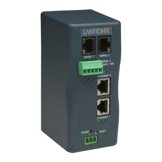
Lantronix XPress DR+ Manuals
Manuals and User Guides for Lantronix XPress DR+. We have
5
Lantronix XPress DR+ manuals available for free PDF download: User Manual, Quick Connect
Lantronix XPress DR+ User Manual (116 pages)
Lantronix Network Device User Guide
Brand:
Lantronix
| Category:
Network Hardware
| Size: 5 MB
Table of Contents
Table of Contents
3
Copyright and Trademark
2
Disclaimer & Revisions
2
Chapter 1: Using this Guide
10
Purpose and Audience
10
Summary of Chapters
10
Additional Documentation
11
Chapter 2: Introduction
12
Product Description
12
Figure 2-1. Xpress DR+ (Front)
13
Industrial Automation Protocols
14
Network Protocols (Serial Tunneling)
14
Xpress DR+ Application Examples
15
Figure 2-2. Example of Serial Tunneling
15
Addresses and Port Numbers
16
Figure 2-3. Example of Cascading Multiple Xpress DR+ Units
16
Figure 2-4. Sample Hardware Address
16
Hardware Address
16
IP Address
16
Port Numbers
16
Configuration Methods
17
Chapter 3: Installation and Hardware
18
What's in the Box
18
What Must the User Provide
18
Physically Connecting the Xpress DR
18
Xpress DR+ Front Panel
19
Figure 3-1. Typical Configuration
19
Serial Interface
20
Figure 3-2. Front of Xpress DR
20
Figure 3-4. Screw Terminal Ports
21
Screw Terminal Serial Connectors
21
Table 3-1. RJ45 Serial Connector Pinouts
21
Table 3-2. Serial Screw Terminal Pinout for RS422 (4-Wire)
21
Table 3-3. Serial Screw Terminal Pinout for RS485 (2-Wire)
21
9-Pin RS-232 to Serial RJ45 Cable (P/N 500-103)
22
Figure 3-5. Termination Resistor for 2-Wire Connection
22
Figure 3-6. Lantronix P/N 500-103 RJ45-DB9F Serial Cable Pinout
22
Ethernet Interface
23
Table 3-4. Ethernet Interface Signals
23
Table 3-5.Typical RJ45 Connector
23
Multi-Drop Ethernet Connections
24
Power Requirements
24
Reset Switch
24
Figure 3-7. Multi-Drop Ethernet Connections
24
Leds
25
Figure 3-8. Reset Switch
25
Figure 3-9. Leds on the Xpress DR
25
Dimensions
26
Figure 3-10. Dimensions
26
Table 3-6. Xpress DR+ LED Functions
26
Wall Mount Bracket
27
Product Information Label
27
Figure 3-11. Wall Mount Bracket
27
Figure 3-12. Product Label
27
Chapter 4: Xpress DR+W
28
Application Examples
28
Figure 4-1. Serial Tunneling Infrastructure Network Example
28
Serial Tunneling - Network
28
Ad Hoc Network
29
Figure 4-2. Ad Hoc Network Example
29
Figure 4-3. Serial Tunneling Infrastructure Example
29
Serial Tunneling - Infrastructure
29
Ad Hoc Xpress DR+W Connection
30
Physically Connecting the Xpress DR+W
30
Figure 4-4. Direct Xpress DR+W - To- Xpress DR+W Connection
30
Front Panel Description
31
Figure 4-5. Typical Xpress DR+W Configuration
31
Figure 4-6. Xpress DR+W Front Panel Layout
31
Leds
32
Required Information for Initial Configuration
32
Hardware Address
32
IP Address
32
Table 4-1. Xpress DR+W LED Functions
32
WLAN Settings
33
Installing the Xpress DR+W for Initial Configuration
33
Server Configuration (Option 0)
33
Figure 4-7. Network Mode
34
Figure 4-8. Server Settings
34
IP Address
34
Network Mode (Xpress DR+W Only)
34
Set Gateway IP Address
34
Table 4-2. Bootp/Dhcp/Autoip Options
34
Change DHCP Device Name
35
Change Telnet Configuration Password
35
Netmask: Number of Bits for Host Part
35
WLAN Configuration (Option 4)
35
Table 4-3. Standard IP Network Netmasks
35
Adhoc Network Channel
36
Network Name (SSID)
36
Topology
36
Wep
37
Wpa
38
Fixed or Automatic Data Rate
39
Wpa2/802.11I
39
Transmission Data Rate
40
Next Steps
40
Chapter 5: Using Deviceinstaller
41
Installing Deviceinstaller
41
Assigning an IP Address
41
Accessing the Xpress DR+ Using Deviceinstaller
42
Viewing the Current Configuration
42
Table 5-1. Viewing Current Settings
43
Chapter 6: Configuration Using Web Manager
45
Accessing Xpress DR+ Using Deviceinstaller
45
Network Configuration
46
Figure 6-1. Lantronix Web Manager
46
Automatic IP Address Configuration
47
Figure 6-2. Network Settings
47
Static IP Address Configuration
48
Server Configuration
48
Figure 6-3. Server Settings
49
Host List Configuration
50
Figure 6-4. Hostlist Settings
50
Channel Configuration
51
Serial Settings
51
Figure 6-5. Channel Serial Settings
52
Port Settings
52
Connection Settings - TCP
54
Figure 6-6. TCP Connection Settings
54
Connect Protocol
55
Endpoint Configuration
55
Common Options
56
Connection Settings - UDP
56
Disconnect Mode
56
Datagram Mode
57
Figure 6-7. UDP Connection Settings
57
WLAN Configuration (Xpress DR+W Only)
58
Figure 6-8. WLAN Settings - Ad Hoc Network Type
59
Figure 6-9. WLAN Settings - Infrastructure Network Type
60
Wireless Network Configuration
60
Wireless Network Security
61
Advanced Settings
62
Applying Settings
62
Applying Factory Defaults
62
Chapter 7: Configuration Using Telnet or Serial Port (Setup Mode)
63
Accessing Setup Mode
63
Telnet Connection
63
Figure 7-1. MAC Address
64
Figure 7-2. Setup Menu Options
64
Serial Port Connection
64
Exiting Setup Mode
65
Chapter 8: Setup Mode: Server Configuration
66
Server Configuration (Option 0)
66
Figure 8-1. Network Mode
66
Figure 8-2. Server Settings
66
IP Address
66
Network Mode (Xpress DR+W Only)
66
Netmask: Number of Bits for Host Part
67
Set Gateway IP Address
67
Table 8-1. Bootp/Dhcp/Autoip Options
67
Table 8-2. Standard IP Network Netmasks
67
Change Telnet Configuration Password
68
DHCP Name
68
Chapter 9: Setup Mode: Channel Configuration
69
Channel 1 (Option 1) and Channel 2 (Option 2)
69
Baudrate
69
Figure 9-1. Serial Port Parameters
69
I/F (Interface) Mode
70
Table 9-1. Interface Mode Options
70
Table 9-2. Common Interface Mode Settings
70
Flow
71
Port Number
71
Table 9-3. Flow Control Options
71
Table 9-4. Reserved Port Numbers
71
Connect Mode
72
Table 9-5. Connect Mode Options
72
A) Incoming Connection
73
B) Response
73
C) Active Startup
73
Accept with DTR Active
73
Always Accept
73
Character Response
73
Connect Mode Option
73
Never Accept Incoming
73
No Active Startup
73
With any Character
73
Autostart
74
Figure 9-2. Manual Connection Address Example
74
Hostlist
74
D) Datagram Type
75
Figure 9-3. Hostlist Option
75
Modem Mode
75
Directed UDP
75
E) Modem Mode
75
Data Echo & Modem Response (Verbose) 1 1
76
No Echo
76
Table 9-6. Modem Mode Messages
76
Table 9-7. Modem Mode Commands
77
Auto Increment Source Port
78
Remote IP Address
78
Send the Escape Sequence (+++) in Modem Mode
78
Disconnmode
79
Remote Port
79
Table 9-8. Disconnect Mode Options
79
Flush Mode (Buffer Flushing)
80
Pack Control
80
Table 9-10. Pack Control Options
80
Packing Interval
81
Send Characters
81
Trailing Characters
81
Table 9-9. Flush Mode Options
80
Disconntime (Inactivity Timeout)
81
Channel (Port) Password
82
Send Characters
82
Telnet Terminal Type
82
WLAN Settings (Xpress DR+W Only)
82
Adhoc Network Channel
83
Network Name (SSID)
83
Topology
83
Wep
84
Wpa
85
Fixed or Automatic Data Rate
86
Transmission Data Rate
86
Wpa2/802.11I
86
Enable Power Management
87
Chapter 10: Setup Mode: Advanced Settings
88
Expert Settings (Option 5)
88
ARP Cache Timeout in Seconds
88
Disable Monitor Mode at Bootup
88
Figure 10-1. Expert Settings
88
TCP Keepalive Time in Seconds
88
Enable Alternate MAC
89
HTTP Port Number
89
MTU Size
89
Security Settings (Option 6)
89
Figure 10-2. Security Settings
89
Disable Port 77FE (Hex)
90
Disable SNMP
90
Disable Telnet Setup
90
Disable TFTP Firmware Upgrade
90
SNMP Community Name
90
Disable ECHO Ports
91
Disable Web Server
91
Disable Web Setup
91
Enable Enhanced Password
91
Default Settings (Option 7)
91
Channel 1 and Channel 2 Configuration Settings
91
Expert Settings
92
Security Settings
92
WLAN Settings (Xpress DR+W Only)
92
Chapter 11: Firmware Upgrades
93
Obtaining Firmware
93
Reloading Firmware
93
Table 11-1. Firmware Files
93
Using TFTP: Graphical User Interface
93
Figure 11-1. TFTP Window
94
Recovering the Firmware Using the Serial Port and Deviceinstaller
94
Using TFTP: Command Line Interface
94
Chapter 12: Monitor Mode
96
Entering Monitor Mode Using the Serial Port
96
Entering Monitor Mode Using the Network Port
96
Monitor Mode Commands
96
Figure 12-1. Accessing Monitor Mode
96
Table 12-1. Monitor Mode Commands
97
Chapter 13: Troubleshooting and Technical Support
99
Problems and Error Messages
99
Table 13-1. Problems and Error Messages
99
Technical Support
102
Appendix A: Technical Specifications
103
Table 13-2. Xpress DR+ and Xpress DR+W Specifications
103
Table 13-3. Xpress DR+W Wireless Specifications
104
Appendix B: Lantronix Cables and Adapters
105
Appendix C: Alternative Methods of Assigning an IP Address
106
Dhcp
106
Autoip
106
Bootp
107
ARP and Telnet
107
Appendix D: Binary to Hexadecimal Conversions
108
Converting Binary to Hexadecimal
108
Conversion Table
108
Scientific Calculator
108
Appendix E: Compliance Information
110
Declaration of Conformity
110
Table 13-4. Electromagnetic Emissions and Immunity - Xpress DR
110
Table 13-5. Electromagnetic Emissions and Immunity - Xpress DR+W
111
Manufacturer's Contact
111
Supplementary Information
111
Xpress DR+W Regulatory Information
112
Canada - Industry Canada Notice
112
USA Federal Communications Commission (FCC) Notice
112
Europe - R&TTE Directive 99/5/EC, Wireless Notice
113
Australia & New Zealand - Wireless Notice
114
Appendix F: Warranty
115
Index
116
Advertisement
Lantronix XPress DR+ User Manual (87 pages)
Brand:
Lantronix
| Category:
Network Hardware
| Size: 2 MB
Table of Contents
Table of Contents
3
1 : Using this Guide
9
Purpose and Audience
9
Summary of Chapters
9
Additional Documentation
10
2 : Introduction
11
Product Description
11
Industrial Automation Protocols
12
Figure 2-1. Xpress DR+ (Front)
12
Network Protocols (Serial Tunneling)
13
Application Examples
13
Figure 2-2. Example of Serial Tunneling
14
Figure 2-3. Example of Cascading Multiple Xpress DR+ Units
14
Addresses and Port Numbers
15
Hardware Address
15
IP Address
15
Port Numbers
15
Configuration Methods
15
Figure 2-4. Sample Hardware Address
15
3 : Installation and Hardware
16
What's in the Box
16
What Must the User Provide
16
Physically Connecting the Unit
16
Front Panel Description
17
Figure 3-1. Typical Configuration
17
Serial Interface
18
Figure 3-2. Front Panel Layout
18
Figure 3-3. RJ45 Connector - Front View
18
Table 3-1. RJ45 Serial Connector Pinouts
18
Figure 3-4. Screw Terminal Ports
19
Screw Terminal Serial Connectors
19
Table 3-2. Serial Screw Terminal Pinout for RS422 (4-Wire)
19
Table 3-3. Serial Screw Terminal Pinout for RS485 (2-Wire)
19
9-Pin RS-232 to Serial RJ45 Cable (P/N 500-103)
20
Ethernet Interface
20
Figure 3-5. Termination Resistor for 2-Wire Connection
20
Figure 3-6. 9-Pin RS-232 to Serial RJ45 (P/N 500-103) Pinout Table
20
Figure 3-7. Multi-Drop Ethernet Connections
21
Multi-Drop Ethernet Connections
21
Table 3-4. Ethernet Interface Signals
21
Table 3-5.Typical RJ45 Connector
21
Power Requirements
22
Reset Switch
22
Figure 3-8. Reset Switch
22
Leds
23
Figure 3-9. Leds
23
Table 3-6. LED Functions
23
Dimensions
24
Wall Mount Bracket
24
Figure 3-10. Dimensions
24
Figure 3-11. Wall Mount Bracket
24
Product Information Label
25
Figure 3-12. Product Label
25
4 : Using Deviceinstaller
26
Installing Deviceinstaller
26
Assigning an IP Address
26
Accessing the Xpress DR+ Using Deviceinstaller
27
Viewing the Current Configuration
27
5 : Configuration Using Web-Manager
30
Accessing Xpress DR+ Using Deviceinstaller
30
Network Configuration
31
Figure 5-1. Lantronix Web-Manager
31
Automatic IP Address Configuration
32
Figure 5-2. Network Settings
32
Static IP Address Configuration
33
Server Configuration
33
Figure 5-3. Server Settings
34
Host List Configuration
35
Figure 5-4. Hostlist Settings
35
Channel Configuration
36
Serial Settings
36
Figure 5-5. Channel Serial Settings
37
Connection Settings - TCP
39
Figure 5-6. TCP Connection Settings
39
Connection Settings - UDP
41
Figure 5-7. UDP Connection Settings
42
Applying Settings
43
Applying Factory Defaults
43
6 : Configuration Using Telnet or Serial Port (Setup Mode)
44
Accessing Setup Mode
44
Telnet Connection
44
Serial Port Connection
45
Figure 6-1. MAC Address
45
Figure 6-2. Setup Menu Options
45
Exiting Setup Mode
46
7 : Setup Mode: Server Configuration
47
Server Configuration (Option 0)
47
IP Address
47
Figure 7-1. Server Settings
47
Table 7-1. Bootp/Dhcp/Autoip Options
47
Set Gateway IP Address
48
Netmask: Number of Bits for Host Part
48
Change Telnet Configuration Password
48
DHCP Name
48
Table 7-2. Standard IP Network Netmasks
48
8 : Setup Mode: Channel Configuration
50
Channel 1 (Option 1) and Channel 2 (Option 2)
50
Baudrate
50
Figure 8-1. Serial Port Parameters
50
I/F (Interface) Mode
51
Flow
51
Table 8-1. Interface Mode Options
51
Table 8-2. Common Interface Mode Settings
51
Port Number
52
Connect Mode
52
Table 8-3. Flow Control Options
52
Table 8-4. Reserved Port Numbers
52
A) Incoming Connection
53
Table 8-5. Connect Mode Options
53
B) Response
54
C) Active Startup
54
Figure 8-2. Manual Connection Address Example
55
Figure 8-3. Hostlist Option
55
D) Datagram Type
56
E) Modem Mode
56
Table 8-6. Modem Mode Messages
57
Table 8-7. Modem Mode Commands
58
Send the Escape Sequence (+++) in Modem Mode
59
Auto Increment Source Port
59
Remote IP Address
59
Remote Port
59
Disconnmode
59
Flush Mode (Buffer Flushing)
60
Table 8-8. Disconnect Mode Options
60
Table 8-9. Flush Mode Options
60
Pack Control
61
Packing Interval
61
Trailing Characters
61
Table 8-10. Pack Control Options
61
Send Characters
62
Disconntime (Inactivity Timeout)
62
Telnet Terminal Type
62
Channel (Port) Password
62
9 : Setup Mode: Advanced Settings
63
Expert Settings (Option 5)
63
TCP Keepalive Time in Seconds
63
Figure 9-1. Expert Settings
63
ARP Cache Timeout in Seconds
64
Disable Monitor Mode at Bootup
64
HTTP Port Number
64
MTU Size
64
Enable Alternate MAC
64
Security Settings (Option 6)
64
Disable SNMP
65
SNMP Community Name
65
Disable Telnet Setup
65
Disable TFTP Firmware Upgrade
65
Figure 9-2. Security Settings
65
Disable Port 77FE (Hex)
66
Disable Web Server
66
Disable Web Setup
66
Disable ECHO Ports
66
Enable Enhanced Password
66
Default Settings (Option 7)
67
Channel 1 and Channel 2 Configuration Defaults
67
Expert Settings Defaults
67
Security Settings Defaults
67
10 : Firmware Upgrades
68
Obtaining Firmware
68
Reloading Firmware
68
Using TFTP: Graphical User Interface
68
Table 10-1. Firmware Files
68
Using TFTP: Command Line Interface
69
Recovering the Firmware Using the Serial Port and Deviceinstaller
69
Figure 10-1. TFTP Window
69
11 : Monitor Mode
71
Entering Monitor Mode Using the Serial Port
71
Entering Monitor Mode Using the Network Port
71
Monitor Mode Commands
71
Figure 11-1. Accessing Monitor Mode
71
Table 11-1. Monitor Mode Commands
72
12 : Troubleshooting and Technical Support
73
Problems and Error Messages
73
Technical Support
76
A: Technical Specifications
77
B: Lantronix Cables and Adapters
79
C: Alternative Methods of Assigning an IP Address
80
Dhcp
80
Autoip
80
Bootp
81
ARP and Telnet
81
D: Binary to Hexadecimal Conversions
82
Converting Binary to Hexadecimal
82
Conversion Table
82
Scientific Calculator
82
E: Compliance Information
84
Declaration of Conformity
84
Supplementary Information
85
F: Warranty
86
Index
87
Lantronix XPress DR+ User Manual (92 pages)
Industrial Device Server
Brand:
Lantronix
| Category:
Server
| Size: 2 MB
Table of Contents
Table of Contents
4
List of Figures
7
List of Tables
8
1: Using this Guide
9
Purpose and Audience
9
Summary of Chapters
9
Additional Documentation
10
2: Introduction
11
Industrial Automation Protocols
12
Figure 2-1. Xpress DR+ (Front)
12
Network Protocols (Serial Tunneling)
13
Xpress DR+ Application Examples
14
Figure 2-2. Example of Serial Tunneling with Com Port Redirector
14
Addresses and Port Numbers
15
Figure 2-3. Example of Cascading Multiple Xpress DR+ Units
15
Configuration Methods
16
3: Installation and Hardware
17
What's in the Box
17
Connecting the Xpress DR+ Device Server
17
Table 3-1. RJ45 Serial Connector Pinouts
17
Figure 3-1. Typical Configuration
18
Xpress DR+ Front Panel
19
Serial Interface
19
Figure 3-2. Front of Xpress DR
19
Figure 3-3. RJ45 Connector - Front View
20
Table 3-2. Serial Screw Terminal Pinout for RS-422 (4-Wire)
20
Table 3-3. Serial Screw Terminal Pinout for RS-485 (2-Wire)
20
Figure 3-4. Screw Terminal Ports
21
Figure 3-5. Termination Resistor for 2-Wire Connection
21
Ethernet Interface
22
Figure 3-6. Lantronix P/N 500-103-R RJ45-DB9F Serial Cable Pinout
22
Table 3-4. Ethernet Interface Signals
22
Power Requirements
23
Figure 3-7. Multi-Drop Ethernet Connections
23
Table 3-5.Typical RJ45 Connector (View from Connector End)
23
Reset Switch
24
Figure 3-8. Reset Switch
24
Leds
25
Figure 3-9. Leds on the Xpress DR
25
Table 3-6. Xpress DR+ LED Functions
25
Dimensions
26
Wall Mount Bracket
26
Figure 3-10. Dimensions
26
Figure 3-11. Wall Mount Bracket
26
Product Information Label
27
Figure 3-12. Product Label
27
4: Using Deviceinstaller
28
Installing Deviceinstaller
28
Assigning an IP Address
28
Accessing the Xpress DR+ Using the Deviceinstaller Application
29
Table 4-1. Viewing Current Settings
29
5: Configuration Using Web Manager
32
Accessing Xpress DR+ Using Deviceinstaller
32
Figure 5-1. Lantronix Web Manager
33
Network Configuration
34
Figure 5-2. Network Settings
34
Server Configuration
36
Figure 5-3. Server Settings
36
Host List Configuration
37
Channel Configuration
38
Figure 5-4. Hostlist Settings
38
Figure 5-5. Channel Serial Settings
39
Figure 5-6. TCP Connection Settings
42
Figure 5-7. UDP Connection Settings
45
Applying Settings
46
Applying Factory Defaults
46
Figure 5-8. Apply Settings
46
6: Configuration Using Telnet/Serial Port (Setup Mode)
47
Accessing Setup Mode
47
Figure 6-1. MAC Address
48
Figure 6-2. Setup Menu Options
48
Exiting Setup Mode
49
7: Setup Mode: Server Configuration
50
Server Configuration (Option 0)
50
Table 7-1. Bootp/Dhcp/Autoip Options
50
Table 7-2. Standard IP Network Netmasks
51
8: Setup Mode: Channel Configuration
53
Channel 1 (Option 1) and Channel 2 (Option 2)
53
Baudrate
53
Figure 8-1. Serial Port Parameters
53
Interface (I/F) Mode
54
Table 8-1. Interface Mode Options
54
Table 8-2. Common Interface Mode Settings
54
Flow
55
Port Number
55
Table 8-3. Flow Control Options
55
Table 8-4. Reserved Port Numbers
55
Connect Mode
56
Table 8-5 Connect Mode Options
56
Table 8-6 Manual Connection Address Example
58
Figure 8-2 Hostlist Option
59
Table 8-7 Modem Mode Messages
61
Send the Escape Sequence (+++) in Modem Mode
62
Table 8-8 Modem Mode Commands
62
Show IP Address after Ring
63
Auto Increment Source Port
63
Remote IP Address
63
Remote Port
63
Disconnmode
63
Flush Mode (Buffer Flushing)
64
Table 8-9 Disconnect Mode Options
64
Table 8-10 Flush Mode Options
64
Pack Control
65
Table 8-11 Pack Control Options
65
Disconntime (Inactivity Timeout)
66
Send Characters
66
Telnet Terminal Type
67
Channel (Port) Password
67
9: Setup Mode: Advanced Settings
68
Expert Settings (Option 5)
68
Figure 9-1. Expert Settings
68
Security Settings (Option 6)
69
Figure 9-2. Security Settings
69
Default Settings (Option 7)
72
10: Firmware Upgrades
74
Obtaining Firmware
74
Reloading Firmware
74
Table 10-1. Firmware Files
74
Figure 10-1. TFTP Window
75
11: Monitor Mode
77
Figure 11-1. Accessing Monitor Mode
77
Table 11-1. Monitor Mode Commands
78
Table 11-2. Command Response Codes
79
12: Troubleshooting
80
Problems and Error Messages
80
Table 12-1. Problems and Error Messages
80
Dhcp
87
Autoip
87
Bootp
88
ARP and Telnet
88
Converting Binary to Hexadecimal
89
Rohs, REACH and WEEE Compliance Statement
92
Advertisement
Lantronix XPress DR+ User Manual (26 pages)
Industrial Device Server
Brand:
Lantronix
| Category:
Server
| Size: 2 MB
Lantronix XPress DR+ Quick Connect (2 pages)
Industrial Device Server
Brand:
Lantronix
| Category:
Server
| Size: 0 MB
Advertisement
Related Products
Lantronix XPress DR+W
Lantronix XPress DR
Lantronix XPress DR-IAP
Lantronix XPress DR plus W
Lantronix XPort
Lantronix xPico WiFi
Lantronix x6010
Lantronix Xpress-Pro SW 52000
Lantronix Xpress-Pro SW 92000
Lantronix Xpress-Pro SW 94000
Lantronix Categories
Server
Switch
Gateway
Network Hardware
Print Server
More Lantronix Manuals
Login
Sign In
OR
Sign in with Facebook
Sign in with Google
Upload manual
Upload from disk
Upload from URL