Lantronix XPress DR+ User Manual
Lantronix network device user guide
Hide thumbs
Also See for XPress DR+:
- User manual (92 pages) ,
- Quick connect (2 pages) ,
- User manual (26 pages)
Table of Contents
Advertisement
Quick Links
Advertisement
Chapters
Table of Contents

Related Manuals for Lantronix XPress DR+


Summary of Contents for Lantronix XPress DR+
- Page 1 XPress DR+ User Guide Part Number 900-422 Revision B October 2006...
-
Page 2: Copyright And Trademark
Copyright & Trademark © 2006, Lantronix. All rights reserved. No part of the contents of this book may be transmitted or reproduced in any form or by any means without the written permission of Lantronix. Printed in the United States of America. -
Page 3: Table Of Contents
Power Requirements ________________________________________________ 24 Reset Switch ______________________________________________________ 24 LEDs ____________________________________________________________ 25 Dimensions _______________________________________________________ 26 Wall Mount Bracket _________________________________________________ 27 Product Information Label ____________________________________________ 27 Chapter 4: XPress DR+W Application Examples________________________________________________ 28 Serial Tunneling – Network _______________________________________________ 28 XPress DR+ User Guide... - Page 4 Required Information for Initial Configuration______________________________ 32 Hardware Address ______________________________________________________ 32 IP Address ____________________________________________________________ 32 WLAN Settings _________________________________________________________ 33 Installing the XPress DR+W for Initial Configuration ________________________ 33 Server Configuration (Option 0) ________________________________________ 33 Network Mode (XPress DR+W only) ________________________________________ 34 IP Address ____________________________________________________________ 34...
- Page 5 Serial Settings _________________________________________________________ 51 Connection Settings - TCP________________________________________________ 54 Connection Settings - UDP _______________________________________________ 56 WLAN Configuration (XPress DR+W only) _______________________________ 58 Applying Settings ___________________________________________________ 62 Applying Factory Defaults ____________________________________________ 62 Chapter 7: Configuration Using Telnet or Serial Port (Setup Mode)
- Page 6 DisConnTime (Inactivity Timeout) ______________________________________ 81 Send Characters ___________________________________________________ 82 Telnet Terminal Type ________________________________________________ 82 Channel (Port) Password_____________________________________________ 82 WLAN Settings (XPress DR+W Only) ___________________________________ 82 Topology______________________________________________________________ 83 Network Name (SSID) ___________________________________________________ 83 Adhoc Network Channel _________________________________________________ 83 WEP _________________________________________________________________ 84 WPA _________________________________________________________________ 85 WPA2/802.11i _________________________________________________________ 86...
- Page 7 Default Settings (Option 7)____________________________________________ 91 Channel 1 and Channel 2 Configuration Settings ______________________________ 91 Expert Settings _________________________________________________________ 92 Security Settings _______________________________________________________ 92 WLAN Settings (XPress DR+W only)________________________________________ 92 Chapter 11: Firmware Upgrades Obtaining Firmware _________________________________________________ 93 Reloading Firmware_________________________________________________ 93 Using TFTP: Graphical User Interface _______________________________________ 93...
- Page 8 Figure 4-2. Ad Hoc Network Example ... 29 Figure 4-3. Serial Tunneling Infrastructure Example... 29 Figure 4-4. Direct XPress DR+W - to- XPress DR+W Connection ... 30 Figure 4-5. Typical XPress DR+W Configuration... 31 Figure 4-6. XPress DR+W Front Panel Layout ... 31 Figure 4-7.
- Page 9 Table 13-2. XPress DR+ and XPress DR+W Specifications... 103 Table 13-3. XPress DR+W Wireless Specifications... 104 Table 13-4. Electromagnetic Emissions and Immunity – XPress DR+ ... 110 Table 13-5. Electromagnetic Emissions and Immunity – XPress DR+W... 111 XPress DR+ User Guide...
-
Page 10: Chapter 1: Using This Guide
Chapter 1: Using This Guide Purpose and Audience This manual describes the Lantronix XPress DR+ and XPress DR+W device servers. These device servers are members of the XPress family that work with Industrial Automation Protocols. The XPress DR+ W has wireless as well as wired capability. -
Page 11: Additional Documentation
Hexadecimal Conversions Appendix E: Compliance Information Appendix F: Warranty Additional Documentation The following guides are available on the product CD and the Lantronix web site (www.lantronix.com). XPress DR+ Quick Start or XPress DR+W Quick Start Com Port Redirector Quick Start... -
Page 12: Chapter 2: Introduction
Information specific to the wireless version of the XPress DR+ unit is in Chapter 4: XPress DR+W. Note: In this User Guide we sometimes refer to the XPress DR+W as "the wireless unit" or the "wireless device server." Product Description The Lantronix XPress DR+ Industrial Device Server is a robust, feature-rich, and cost effective way to network-enable equipment in an industrial automation environment. -
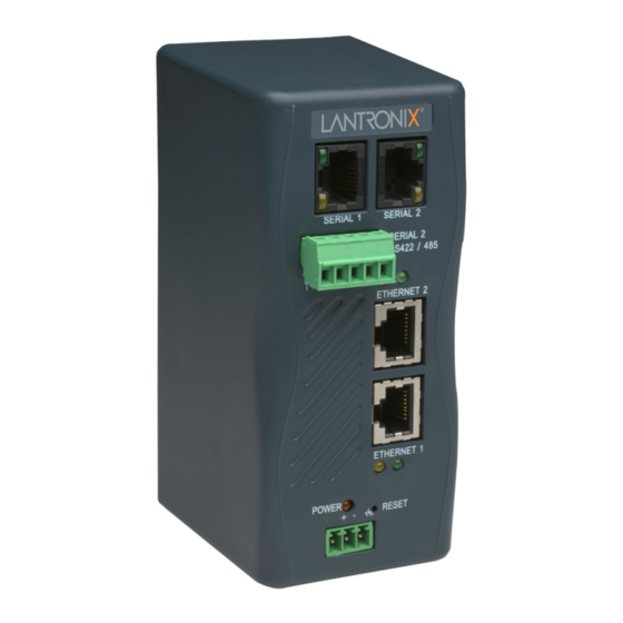
Page 13: Figure 2-1. Xpress Dr+ (Front)
Communication can be established from the XPress DR+ to a host computer or another device or from a host computer or device to the XPress DR+. Note: For a diagram and description of XPress DR+W, see Description on page The XPress DR+ supports RS-232 through RJ45 connectors. It also supports RS-422/485 by means of screw terminals (Serial Port 2 only). -
Page 14: Industrial Automation Protocols
For information about using any of the industrial communication protocols, see the specific protocol guides on the software CD or the Lantronix web site. Protocol firmware files are also on the CD. Note: Please check the Lantronix web site for newer versions that may become available. -
Page 15: Xpress Dr+ Application Examples
Standard Tunnel Protocol. XPress DR+ Application Examples Note: For XPress DR+W application examples, see Using a method called serial tunneling, the XPress DR+ encapsulates serial data into packets and transports them over Ethernet. Using two XPress DR+ units, connected by a network, you can extend virtual serial connections across a facility or around the world. -
Page 16: Addresses And Port Numbers
The hardware address is also referred to as the Ethernet address or MAC address. The first three bytes of the Ethernet address are fixed and read 00-20-4A, identifying the unit as a Lantronix product. The fourth, fifth, and sixth bytes are unique numbers assigned to each unit. -
Page 17: Configuration Methods
Telnet connection to the network port (9999) or connecting a terminal (or a PC running a terminal emulation program) to the unit’s serial port. To use DeviceInstaller for communication to an XPress DR+W over a wireless network, the WLAN network settings must be configured first. -
Page 18: Chapter 3: Installation And Hardware
The following diagram shows the basic connectivity of an XPress DR+ to the network and a serial device. The Lantronix-supplied P/N: 500-103 serial cable can be used on the RJ45 RS232 serial ports to connect the XPress DR+ to a PC or to a serial device that has a DB9M RS232 DTE interface. -
Page 19: Xpress Dr+ Front Panel
XPress DR+ Front Panel The following figure illustrates the screw block connector pinouts and other components of the XPress DR+. Note: For a description of the XPress DR+W front panel, see DR+W. XPress DR+ User Guide Figure 3-1. Typical Configuration Power Requirements on page 24.) -
Page 20: Serial Interface
Chapter 3: Installation and Hardware Figure 3-2. Front of XPress DR+ Serial Interface The XPress DR+ supports RS-232 via RJ45 connectors. It also supports RS-422/485 via screw terminals (Serial Port 2 only). Note: Serial Port 2 supports RS232, RS422, and RS485, but only one mode at a time. -
Page 21: Screw Terminal Serial Connectors
Table 3-1. RJ45 Serial Connector Pinouts Direction Name Output from DR+ Output from DR+ Output from DR+ Ground Ground Input to DR+ Input to DR+ Input to DR+ Screw Terminal Serial Connectors Table 3-2. Serial Screw Terminal Pinout for RS422 (4-Wire) Table 3-3. -
Page 22: 9-Pin Rs-232 To Serial Rj45 Cable (P/N 500-103)
PC Com port to the XPress DR+ serial port. This cable is pinned to provide full serial line control to an RS232 DTE device. Lantronix offers a comprehensive list of cables and adapters to simplify device connectivity to the XPress DR+. -
Page 23: Ethernet Interface
Ethernet Interface The XPress DR+ includes a two-port unmanaged Ethernet switch with a future option to migrate to a managed solution. The internal IEEE 802.3-compliant Ethernet switch is non-blocking, using a 1K MAC address lookup table with store-and-forward architecture. The XPress DR+ supports auto-negotiation for 10Base-T or 100Base-TX in full and half-duplex modes, as well as automatic MDI/MDIX crossover, allowing use of both straight-through and crossed Ethernet cables. -
Page 24: Multi-Drop Ethernet Connections
Multi-Drop Ethernet Connections Although there are two Ethernet ports, the XPress DR+ only has one MAC address and IP address. Either port can be used as the primary connection with the other used to inter-connect other Ethernet devices or cascade from one XPress DR+ to another. Figure 3-7. -
Page 25: Leds
ESD. A chassis ground must be connected to earth. LEDs Note: For a description of the XPress DR+W's LEDs, see page 32. Power/Diagnostic LED XPress DR+ User Guide Figure 3-8. Reset Switch Figure 3-9. LEDs on the XPress DR... -
Page 26: Dimensions
Serial port - TXD LED (Yellow) Serial port - RXD LED (Green) Ethernet port - 10/100 Link (Green) Ethernet port – Activity (Yellow) Power/Diagnostic LED (Orange) Dimensions The following drawing shows the dimensions of the XPress DR+ XPress DR+ User Guide Table 3-6. -
Page 27: Wall Mount Bracket
Wall Mount Bracket Included with the XPress DR+ is an accessory DIN-rail wall mount bracket that makes it very easy to mount the unit in locations where a DIN-rail is not available. Product Information Label The product information label on the underside of the unit contains important information about your specific unit: Bar code Serial number... -
Page 28: Chapter 4: Xpress Dr+W
WPA security. Application Examples The XPress DR+W has an 802.11b/g transceiver in addition to its serial and Ethernet ports. Each serial port is connected to the serial communication port of a device. The wireless transceiver connects to another wireless device or to an Access Point (AP). This section includes typical scenarios for using the XPress DR+W. -
Page 29: Ad Hoc Network
Chapter 4: XPress DR+W connected to it. The combination of the XPress DR+W, a PC, and Lantronix’s Com Port Redirector software allows the PC to communicate directly to the wireless unit’s serial devices, providing wireless serial tunneling. Com Port Redirector is available on the product CD and the Lantronix web site (www.lantronix.com). -
Page 30: Ad Hoc Xpress Dr+W Connection
In the example above, the XPress DR+W communicates with another device server via the AP. The UDS device server, in this example, is connected via an Ethernet connection to the AP. In this way, the XPress DR+W and the device server communicate directly and can transfer information between their serial devices. -
Page 31: Front Panel Description
Chapter 4: XPress DR+W Figure 4-5. Typical XPress DR+W Configuration Front Panel Description The following figure illustrates the screw block connector pinouts and other components of the XPress DR+W. Figure 4-6. XPress DR+W Front Panel Layout XPress DR+ User Guide... -
Page 32: Leds
Hardware Address: 00-20-4a-_____-_____-_____ IP Address The XPress DR+W must have a unique IP address on the network. The systems administrator generally provides the IP address, subnet mask, and gateway. XPress DR+ User Guide Table 4-1. XPress DR+W LED Functions... -
Page 33: Wlan Settings
2. Connect the other end of the serial cable to a terminal or a PC’s serial COM port. 3. On the PC, open a terminal emulation application (e.g. HyperTerminal). Configure the XPress DR+W serial settings as 9600 baud, 8 bits, not parity, 1 stop bit, and no flow control (9600, 8, N, 1). -
Page 34: Network Mode (Xpress Dr+W Only)
Network Mode (XPress DR+W only) The first prompt requires you to set the unit for wired or wireless use. Wireless is the default, so just press Enter at the prompt. The IP Address, Set Gateway IP Address, and Netmask fields display the current values. -
Page 35: Netmask: Number Of Bits For Host Part
Due to regulations, the country-specific setting has been removed from the setup menu and Web Manager. We provide a separate utility for changing the Country/Zone setting. The utility is called SetZone and is included in the XPress DR+W package. It is also available for download from the Lantronix web site. -
Page 36: Topology
Channel (11) ? _ Only channels allowed in the country for which the XPress DR+W is designated can be selected. The country displays in the Setup Mode settings overview. Security The Security Suite prompt enables you to select the type of security. -
Page 37: Wep
TKIP+WEP. A group encryption lower than the pairwise encryption is necessary to use higher security with the XPress DR+W than other devices connecting to the same Access Point can support. CCMP is also called AES on products of other manufacturers. CCMP is an extension of AES. -
Page 38: Wpa
Key Type Encryption Key Passphrase input is not the same as ASCII input. The passphrase input is safer because it has up to 63 characters. ASCII input has a maximum of 5 (WEP64) or 13 (WEP128) characters and limits the number of key combinations. -
Page 39: Wpa2/802.11I
For example CCMP+TKIP => pairwise = CCMP, and group = TKIP. Fixed or Automatic Data Rate The XPress DR+W can control the transmission rate. Select 0 to set a fixed data rate, or select 1 to set an automatic data rate. The default setting is 1 (auto). -
Page 40: Transmission Data Rate
Transmission Data Rate If the above TX Data rate is set to fixed, the selected data rate is the XPress DR+W’s fixed transmission rate. If the above TX Data rate is set to auto, the selected data rate is the XPress DR+W’s maximum data rate. Lower data rates allow for larger distances. -
Page 41: Chapter 5: Using Deviceinstaller
This chapter covers the steps for getting the XPress DR+ device server online and viewing its current configuration. Note: For the latest firmware, release notes, and user documentation, go to the Lantronix web site (www.lantronix.com). Installing DeviceInstaller To install DeviceInstaller: Insert the product CD into your CD-ROM drive. -
Page 42: Accessing The Xpress Dr+ Using Deviceinstaller
Note: If the unit already has an IP address (e.g., DHCP has assigned an IP address), click the Search icon and select the unit from the list of Lantronix device servers on the local network. 2. Click the Assign IP icon 3. -
Page 43: Table 5-1. Viewing Current Settings
Setting Name Group Comments Device Family Type Hardware Address Firmware Version Extended Firmware Version Online Status Telnet Enabled Telnet Port Web Enabled Web Port Maximum Baud Rate Supported Firmware Upgradeable IP Address Number of COB partitions supported XPress DR+ User Guide Table 5-1. - Page 44 Setting Supports Dynamic IP DHCP BOOTP RARP Subnet Mask Gateway Number of Ports TCP Keepalive Supports Configurable Pins Supports Email Triggers Supports AES Data Stream Supports 485 Supports 920K Baudrate Supports HTTP Server Supports HTTP Setup Supports 230K Baud Rate Supports GPIO XPress DR+ User Guide Description...
-
Page 45: Chapter 6: Configuration Using Web Manager
For the latest firmware, release notes, and user documentation, go to the Lantronix web site (www.lantronix.com). To use Web Manager for communication to an XPress DR+W over a wireless network, you must first configure the network and WLAN settings using a serial connection. -
Page 46: Network Configuration
IP address of the XPress DR+. The main menu is in the left pane of the Web Manager window. Note: The WLAN option applies only to the XPress DR+W. Network Configuration The unit’s network values display when you select Network from the main menu. The following sections describe the configurable parameters on the Network Settings page. -
Page 47: Automatic Ip Address Configuration
Automatic IP Address Configuration An IP address can be assigned automatically. You then enter related network settings. To assign an IP address automatically: 1. On the main menu, click Network. 2. (Wireless units only) From the Network Mode drop-down list, select Wired Only or Wireless Only to set the unit for wired or wireless use. -
Page 48: Static Ip Address Configuration
Note: Disabling BOOTP, DHCP, and AutoIP (all three checkboxes) is not advised as the only available IP assignment method will then be ARP or the serial port. 5. When finished, click the OK button. 6. To save and reboot, click Apply Settings on the main menu. Static IP Address Configuration You manually assign an IP address to the unit and enter related network settings. -
Page 49: Figure 6-3. Server Settings
To configure the unit's device server settings: 1. On the main menu, click Server. 2. Configure or modify the following fields: Server Configuration Telnet Password Retype Password Advanced ARP Cache Timeout TCP Keepalive Monitor Mode @ Bootup HTTP Server Port XPress DR+ User Guide Figure 6-3. -
Page 50: Host List Configuration
0x77FE Server Port MTU Size 3. When you are finished, click the OK button. 4. To save and reboot, on the main menu, click Apply Settings. Host List Configuration The XPress DR+ scrolls through the host list until it connects to a device listed in the host list table. -
Page 51: Channel Configuration
Retry Settings Retry Counter Retry Timeout Host Information Host Address Port 3. When finished, click the OK button. 4. To save and reboot, click Apply Settings on the main menu. Channel Configuration The Channel 1 and Channel 2 configurations define how the serial ports respond to network and serial Note: Channel 1 and Channel 2 have the same defaults except for the port number... -
Page 52: Port Settings
2. In the available fields, enter the following information: Channel 1 Disable Serial Port Port Settings Protocol Flow Control Baud Rate Data Bits Parity Stop Bits XPress DR+ User Guide Figure 6-5. Channel Serial Settings When selected, disables communication through the serial port. - Page 53 Pack Control Enable Packing Idle Gap Time Match 2 Byte Sequence Match Bytes Send Frame Only Send Trailing Bytes Flush Input Buffer (Serial to Network) With Active Connect With Passive Connect At Time of Disconnect Flush Output Buffer (Network to Serial) With Active Connect With Passive Connect At Time of Disconnect...
-
Page 54: Connection Settings - Tcp
Chapter 6: Configuration Using Web Manager Connection Settings - TCP To configure a channel’s TCP settings: 1. On the main menu, click Connection. The Connection Settings window for the channel displays. Figure 6-6. TCP Connection Settings XPress DR+ User Guide... -
Page 55: Endpoint Configuration
2. In the available fields, enter or modify the following information: Connect Protocol Protocol Connect Mode: Passive Connection Accept Incoming Password Required Password Connect Mode: Active Connection Active Connect Start Character Modem Mode Endpoint Configuration Local Port Auto increment for active connect Remote Port Remote Host... -
Page 56: Common Options
Common Options Telnet Mode Terminal Name Connect Response Use Hostlist Disconnect Mode On Mdm_Ctrl_In Drop Hard Disconnect With EOT Inactivity Timeout 3. When finished, click the OK button. 4. To save and reboot, click Apply Settings on the main menu. Connection Settings - UDP To configure a channel’s UDP settings: 1. -
Page 57: Datagram Mode
Connect Protocol Protocol Datagram Mode Datagram Type Accept Incoming XPress DR+ User Guide Figure 6-7. UDP Connection Settings Select UDP from the drop-down menu. Configures the remote IP or network broadcast address and the remote port. Enter 01 for directed or broadcast UDP. The default setting is 00. -
Page 58: Wlan Configuration (Xpress Dr+W Only)
Due to regulations, the country-specific setting has been removed from the setup menu and Web Manager. However, we provide a separate utility for changing the Country/Zone setting. The utility is called SetZone and is included on the XPress DR+W CD. It is also available for download from the Lantronix web site. -
Page 59: Figure 6-8. Wlan Settings - Ad Hoc Network Type
Chapter 6: Configuration Using Web Manager To configure the XPress DR+W’s WLAN settings: 1. Select WLAN from the main menu to open the WLAN Settings window. Figure 6-8. WLAN Settings – Ad Hoc Network Type XPress DR+ User Guide... -
Page 60: Figure 6-9. Wlan Settings - Infrastructure Network Type
Figure 6-9. WLAN Settings – Infrastructure Network Type Enter or modify the following fields: Wireless Network Configuration Network Name (SSID) Network Type Channel XPress DR+ User Guide Enter the name of the wireless network (SSID). The XPress DR+W connects to this wireless network. Select Infrastructure or Ad Hoc. -
Page 61: Wireless Network Security
Encryption Key Type XPress DR+ User Guide As a security measure, enable WEP, WPA, or WPA2/802.11i on the XPress DR+W. WPA and WPA2/802/11i are not available when Ad Hoc is the network type. By default, wireless security is disabled. Note: The WPA2/802.11i mode complies with the Robust... -
Page 62: Advanced Settings
A passphrase of more than 20 characters is recommended. Spaces and punctuation characters are permitted. The XPress DR+W permits the control of the transmission data rate. Click the Auto check box to allow the unit to automatically set the data rate (or leave it unchecked to set the transmission rate manually). -
Page 63: Chapter 7: Configuration Using Telnet Or Serial Port (Setup Mode)
For the latest firmware, release notes, and user documentation, go to the Lantronix web site (www.lantronix.com). To use Telnet for communication to an XPress DR+W over a wireless network, you must first configure the network and WLAN settings using a serial connection. See... -
Page 64: Serial Port Connection
1. Connect a console terminal (VT100) or PC running a terminal emulation program from port 1 with the Lantronix supplied P/N: 500-103 RJ45-to-DB9F serial cable. The default serial port settings are 9600 baud, 8 bits, no parity, 1-stop bit, no-flow control. -
Page 65: Exiting Setup Mode
At this point, the screen display is the same as when you use a Telnet connection. To continue, go to step 3 in Telnet Connection above. Exiting Setup Mode To exit setup mode: You have two options: To save all changes and reboot the device, select option 9 Save and exit from the Change Setup menu. -
Page 66: Chapter 8: Setup Mode: Server Configuration
(option 0). Note: Current values display in parentheses. Network Mode (XPress DR+W only) The first prompt requires you to set the unit for wired or wireless use. Wired is the default. The IP Address, Set Gateway IP Address, and Netmask fields display the current values. -
Page 67: Set Gateway Ip Address
For example, if the third octet is 0.0.5.0, the AutoIP and BootP options are disabled; only DHCP is enabled. (The value 5 results from adding the binary equivalents of 0 and 2.) This is the most common setting when using DHCP. Set Gateway IP Address The gateway address, or router, allows communication to other LAN segments. -
Page 68: Change Telnet Configuration Password
Change Telnet Configuration Password Setting the Telnet configuration password prevents unauthorized access to Setup Mode through a Telnet connection to port 9999 or through web pages. The password must have 4 characters. Change telnet config password (N) ? _ An enhanced password setting (for Telnet access only) of 16 characters is available under Security Settings (Option 6) on page 89. -
Page 69: Chapter 9: Setup Mode: Channel Configuration
Chapter 9: Setup Mode: Channel Configuration This chapter explains how to configure a serial port. Notes: Current values display in parenthesis. You must enter some values in hexadecimal notation. (See Hexadecimal Conversions). Channel 1 (Option 1) and Channel 2 (Option 2) Note: Channel 1 and Channel 2 have the same defaults except for the port number (10001 for Channel 1 and 10002 for Channel 2). -
Page 70: I/F (Interface) Mode
I/F (Interface) Mode The Interface (I/F) Mode is a bit-coded byte entered in hexadecimal notation. I/F Mode (4C) ? _ The following table displays available I/F Mode options. Note: All bit positions in the table that are blank represent “don’t care” bits for that particular option, which can be set to either a 0 or 1 value. -
Page 71: Flow
Flow Flow control sets the local handshaking method for stopping serial input/output. Flow (0) ? _ Use the following table to select flow control options: Flow Control Option No flow control XON/XOFF flow control Hardware handshake with RTS/CTS lines XON/XOFF pass characters to host Port Number The setting represents the source port number in TCP connections. -
Page 72: Connect Mode
Connect Mode Connect Mode defines how the unit makes a connection, and how it reacts to incoming connections over the network. ConnectMode (C0) ? _ Enter Connect Mode options in hexadecimal notation. Note: All bit positions in the table that are blank represent “don’t care” bits, for that particular option, which can be set to either a 0 or 1 value. -
Page 73: A) Incoming Connection
Connect Mode Option Modem Response Only (Numeric) Modem Response Only (Verbose) a) Incoming Connection Never Accept Incoming Accept with DTR Active Always Accept b) Response Character Response c) Active Startup No Active Startup With Any Character With DTR Active With a Specific Start Character Manual Connection XPress DR+ User Guide... -
Page 74: Figure 9-2. Manual Connection Address Example
Figure 9-2. Manual Connection Address Example Command String C121.2.4.5/1 C28.10/12 C0.0.0.0/0 Autostart (Automatic Connection) Hostlist XPress DR+ User Guide If a partial IP address is presented in a command string, it is interpreted to be the least significant bytes of the IP address and uses the internally stored remote IP address to provide the most significant bytes of the IP address. -
Page 75: D) Datagram Type
3. After completing the hostlist, repeat the previous step if necessary to edit the hostlist again. 4. For Retrycounter, enter the number of times the Lantronix unit should try to make a good network connection to a hostlist entry that it has successfully ARPed. The range is 1-15, with the default set to 3. -
Page 76: Table 9-6. Modem Mode Messages
Normally, there is a modem connected to a local PC and a modem connected to a remote machine. A user must dial from the local PC to the remote machine, accumulating phone charges for each connection. Modem Mode allows you to replace modems with XPress DR+ units, and to use an Ethernet connection instead of a phone call. -
Page 77: Table 9-7. Modem Mode Commands
The unit ignores any character sequence received not starting with AT, and only recognizes and processes single AT-style commands. The unit treats compound AT commands as unrecognized commands. If the Full Verbose option is in effect, the unit responds to an unrecognized command string that is otherwise formatted correctly (begins with AT and ends with carriage return) with the "OK"... -
Page 78: Send The Escape Sequence (+++) In Modem Mode
Modem Mode Command ATS0=n ATEn ATVn Note: The unit recognizes these AT commands as single commands such as ATE0 or ATV1; it does not recognize compound commands such as ATE0V. Send the Escape Sequence (+++) in Modem Mode Send ‘+++’ in Modem Mode (Y) ? _ Disable or enable the unit's ability to send the escape sequence. -
Page 79: Remote Port
Remote Port You must set the remote TCP port number for the unit to make outgoing connections. This parameter defines the port number on the target host to which a connection is attempted. Remote Port ( 0) ? _ To connect an ASCII terminal to a host using the unit for login purposes, use the remote port number 23 (Internet standard port number for Telnet services). -
Page 80: Flush Mode (Buffer Flushing)
Flush Mode (Buffer Flushing) Using this parameter, you can control line handling and network buffers with connection startup and disconnect. FlushMode ( 0) ? _ You can also select between two different packing algorithms. Note: All bit positions in the table that are blank represent “don’t care” bits, for that particular option, which can be set to either a 0 or 1 value. -
Page 81: Packing Interval
Option Interval: 250ms Interval: 5sec Trailing Characters None Send Characters 2-Byte Send Character Sequence Send Immediately After Send chars Packing Interval Packing Interval defines how long the unit should wait before sending accumulated characters. This wait period is between successive network segments containing data. For alternate packing, the default interval is 12 ms. -
Page 82: Send Characters
Due to regulations, the country-specific setting has been removed from the setup menu and Web Manager. We provide a separate utility for changing the Country/Zone setting. The utility is called SetZone and is included in the XPress DR+W package. It is also available for download from the Lantronix web site (www.lantronix.com). -
Page 83: Topology
Channel (11) ? _ Only channels allowed in the country for which the XPress DR+W is designated can be selected. The country displays in the Setup Mode settings overview. Security The Security Suite prompt enables you to select the type of security. -
Page 84: Wep
TKIP+WEP. A group encryption lower than the pairwise encryption is necessary to use higher security with the XPress DR+W than other devices connecting to the same Access Point can support. CCMP is also called AES on products of other manufacturers. CCMP is an extension of AES and is the correct term. -
Page 85: Wpa
Key Type Encryption Key A passphrase of more than 20 characters is recommended. Maximum length is 63 characters, including spaces and punctuation characters. Passphrase input is not the same as ASCII input. The passphrase input is safer because it has up to 63 characters. ASCII input has a maximum of 5 (WEP64) or 13 (WEP128) bytes and limits the number of key combinations. -
Page 86: Wpa2/802.11I
TX Data rate 0=fixed, 1=auto fallback (1) ? _ Transmission Data Rate If the above TX Data rate is set to fixed, the selected data rate is the XPress DR+W’s fixed transmission rate. If the above TX Data rate is set to auto, the selected data rate is the XPress DR+W’s maximum data rate. -
Page 87: Enable Power Management
Chapter 9: Setup Mode: Channel Configuration Enable Power Management This allows the software to turn off the radio when expecting not to receive or transmit soon. This feature reduces the power consumption by up to 170 mA. Enabling power management increases the response time, because the radio needs to start up again. The radio is enabled to synchronize and check for incoming messages (every 100 ms). -
Page 88: Chapter 10: Setup Mode: Advanced Settings
Chapter 10: Setup Mode: Advanced Settings Expert Settings (Option 5) Note: You can change these settings using Telnet or serial connections only, not on the Web Manager. Caution: Only a Network Administrator should change these parameters. You must definitely know the consequences the changes might have. TCP Keepalive time in seconds This option allows you to change how many seconds the unit waits during a silent connection before attempting to see if the currently connected network device is still on... -
Page 89: Http Port Number
HTTP Port Number This option allows the configuration of the web server port number. The valid range is 1-65535. The default HTTP port number is 80. HTTP Port Number : (80) ? _ MTU Size The Maximum Transmission Unit (MTU) is the largest physical packet size a network can transmit for TCP and UDP. -
Page 90: Disable Snmp
Disable SNMP This setting allows you to disable the SNMP protocol on the unit for security reasons. Disable SNMP (N) ? _ SNMP Community Name The SNMP Community Name is a required field for NMS to read or write to a device. Enter a string of 1 to 13 characters. -
Page 91: Disable Web Server
Note: The Y (Yes) option disables many of the GUI tools for configuring the unit, including the embedded Web Manager tool. Disable Web Server This setting defaults to the N (No) option. The Y (Yes) option disables the web server. Disable Web Server (N) ? _ Disable Web Setup The Y (Yes) option disables configuration using the Web Manager. -
Page 92: Expert Settings
Disable Telnet setup Disable TFTP Firmware Update Disable Port 77FEh Disable Web Server Disable Web Setup Disable ECHO ports Enable Enhanced password WLAN Settings (XPress DR+W only) Topology Network Name Channel Security suite TX Data Rate TX Data Rate Enable Power Management... -
Page 93: Chapter 11: Firmware Upgrades
DeviceInstaller (the preferred way), using TFTP, or using the serial port. You can also update the unit's internal web interface (*.COB) using TFTP or DeviceInstaller. Here are typical names for those files. Check the Lantronix web site for the latest versions and release notes. -
Page 94: Using Tftp: Command Line Interface
3. For Port on PC, enter the COM port on the PC that is connected to the serial port of the Lantronix unit. XPress DR+ User Guide Figure 11-1. TFTP Window for XPress DR+W) or WEB1 for the internal web pages. _webm_1402.cob WEB1... - Page 95 4. For Device Model, be sure the appropriate XPress DR+ device displays. 5. For Firmware File, click the Browse button and go to the location where the firmware file resides. Note: Make sure the XPress DR+ on which you are recovering firmware is connected to this selected port on your PC.
-
Page 96: Chapter 12: Monitor Mode
Chapter 12: Monitor Mode Monitor Mode is a command-line interface used for diagnostic purposes. There are two ways to enter Monitor Mode: locally using the serial port or remotely using the network. Entering Monitor Mode Using the Serial Port To enter Monitor Mode locally: 1. -
Page 97: Table 12-1. Monitor Mode Commands
Command G0, G1, ...,Ge, Gf GC x.x.x.x PI x.x.x.x S0, S1,...,Se, Sf SC x.x.x.x VS x.x.x.x Responses to some of the commands are in Intel Hex format. Note: Entering any of the commands listed above generates one of the following command response codes XPress DR+ User Guide Table 12-1. - Page 98 Response 0> 1> 2> 8> 9> XPress DR+ User Guide Table 7-2. Command Response Codes Meaning OK; no error No answer from remote device Cannot reach remote device or no answer Wrong parameter(s) Invalid command...
-
Page 99: Chapter 13: Troubleshooting And Technical Support
This chapter discusses how you can diagnose and fix errors quickly without having to contact a dealer or Lantronix. It helps to connect a terminal to the serial port while diagnosing an error to view summary messages that may display. When troubleshooting, always ensure that the physical connections (power cable, network cable, and serial cable) are secure. - Page 100 Problem/Message When you Telnet to port 1 to assign an IP address to the device server, the Telnet window does not respond for a long time. When you try to assign an IP with DeviceInstaller, you get the following : "No response from device! Verify the IP, Hardware Address and Network Class.
- Page 101 Problem/Message You can ping the device server, but not Telnet to the device server on port 9999. The device server appears to be set up correctly, but you are not communicating with your device attached to the device server across the network. When connecting to the Web Manager within the device server, the "No Connection With The...
-
Page 102: Technical Support
Technical Support Europe, Middle East, and Africa Phone: +33 (0) 1 39 30 41 72 Email: eu_techsupp@lantronix.com or eu_support@lantronix.com Firmware downloads, FAQs, and the most up-to-date documentation are available at www.lantronix.com/support When you report a problem, please provide the following information: Your name, and your company name, address, and phone number ... -
Page 103: Appendix A: Technical Specifications
Appendix A: Technical Specifications Table 13-2. XPress DR+ and XPress DR+W Specifications Category Description Lantronix DSTNI-EX 48 MHz clock Internal CPU Memory 256 KB SRAM Flash 2 MB Flash EEPROM 2 KB EEPROM Serial Interface 2 RJ45 RS232 Serial Ports... -
Page 104: Table 13-3. Xpress Dr+W Wireless Specifications
40 A (5/50 ns) EFT protection (IEC 61000-4-4), 12 A (8/20 us) lightning protection (IEC 61000-4-5) on all Ethernet ports Agency Approvals UL, CSA, FCC, CE, TUV, CTick, VCCI, FM Class 1, Div. 2 Table 13-3. XPress DR+W Wireless Specifications Category Frequency Range Output Power... -
Page 105: Appendix B: Lantronix Cables And Adapters
Appendix B: Lantronix Cables and Adapters Lantronix P/N Description 500-103 6’ RJ45-to DB9F 200.2062 Cable Ethernet CAT5; RJ45, 2 m (6.6 ft) 200.2063 Cable Ethernet CAT5; RJ45, 5 m (16.4 ft) 200.2064 Cable Ethernet CAT5; RJ45, 10 m (32.8 ft) 200.2065... -
Page 106: Appendix C: Alternative Methods Of Assigning An Ip Address
Appendix C: Alternative Methods of Assigning an IP Address Earlier chapters describe how to assign a static IP address using DeviceInstaller, Web- Manager, and Setup Mode (through a Telnet or serial connection). This section covers other methods for assigning an IP address over the network. DHCP The unit ships with a default IP address of 0.0.0.0, which automatically enables DHCP. -
Page 107: Bootp
You can disable AutoIP by setting the unit’s IP address to 0.0.1.0. This setting enables DHCP but disables AutoIP. BOOTP Similar to DHCP, but for smaller networks. Automatically assigns the IP address for a specific duration of time. ARP and Telnet If the unit has no IP address, you can use Address Resolution Protocol (ARP). -
Page 108: Appendix D: Binary To Hexadecimal Conversions
Appendix D: Binary to Hexadecimal Conversions Many of the unit’s configuration procedures require you to assemble a series of options (represented as bits) into a complete command (represented as a byte). The resulting binary value must be converted to a hexadecimal representation. Converting Binary to Hexadecimal Following are two simple ways to convert binary numbers to hexadecimal notation. - Page 109 Appendix D: Binary to Hexadecimal Conversions 3. Click Hex. The hexadecimal value displays. XPress DR+ User Guide...
-
Page 110: Appendix E: Compliance Information
Appendix E: Compliance Information Declaration of Conformity (according to ISO/IEC Guide 22 and BS 7514) Manufacturer’s Name & Address Lantronix, 15353 Barranca Parkway, Irvine, CA 92618 USA Declares that the following product: Product Name Model XPress DR+ and XPress DR+W... -
Page 111: Table 13-5. Electromagnetic Emissions And Immunity - Xpress Dr+W
FCC Part 18 Subpart C ICES-001 Issue 4 July 2004 EN61000-6-4: 2001 and AS/NZS 4251.2: 1999 CISPR11 Table 13-5. Electromagnetic Emissions and Immunity – XPress DR+W Emissions: CFR Title 47 FCC Part 15, Subpart B and C, Class B Industry Canada ICES-003 Issue 4 (2004) Class B EN 301 489-1 v1.4.1 (2002-08), EMC Directive... -
Page 112: Xpress Dr+W Regulatory Information
This device must accept any interference received, including interference that may cause undesired operation. Caution: Changes or modifications to this product not expressly approved by Lantronix could void the user's authority to operate this equipment. Note: This equipment has been tested and found to comply with the limits for a Class B digital device, pursuant to part 15 of the FCC Rules. -
Page 113: Europe - R&Tte Directive 99/5/Ec, Wireless Notice
This Class B digital apparatus complies with Canadian ICES-003.” Cet appareil numérique de la classe B est conforme à la norme NMB- 003 du Canada. Antenna Notice: This device has been designed to operate with an antenna having a maximum gain of 3 dBi. -
Page 114: Australia & New Zealand - Wireless Notice
The number “ ACN 095 223 484 “ stands for Australian Company Number and the 9 digit number designates the local representative in Australia who can take inquiries regarding this product’s compliance status. The following contact address is found below: Lantronix Australia Pty. Ltd. c/o LLK Chartered Accountants Suite 2, Level 7... -
Page 115: Appendix F: Warranty
Lantronix, freight prepaid. Upon verification of warranty, Lantronix will -- at its option -- repair or replace the product and return it to the customer freight prepaid. If the product is not under warranty, the customer may have Lantronix repair the unit on a fee basis or return it. -
Page 116: Index
Index Adapters, 105 Addresses Hardware, 16 IP, 16 Applications, 15 XPress-DR+W, 28 ARP and Telnet, 107 AutoIP, 106 Binary to hexadecimals, 108 BOOTP, 107 Cables, 105 Cascading, 16, 24 Channel settings Setup Mode, 69 Web-Manager, 51 Compliance and testing, 110 Configuration methods, 17 Connection settings Setup Mode, 72, 78, 79...
Need help?
Do you have a question about the XPress DR+ and is the answer not in the manual?
Questions and answers