Lantronix xPress DR+ Quick Connect
Industrial device server
Hide thumbs
Also See for xPress DR+:
- User manual (116 pages) ,
- User manual (26 pages) ,
- User manual (87 pages)
Advertisement
Quick Links
xPress DR+
!
Thank you for choosing Lantronix. Please register your product to receive no fica ons for firmware and
documenta
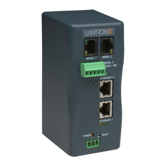
XPRESS DR+
HARDWARE OVERVIEW
PINOUTS
RJ45 Serial Connector Pinout for RS‐232
PIN
DIRECTION
NAME
1
Output from DR+ RTS
2
Output from DR+ DTR
3
Output from DR+ TXD
4
Ground
GND
5
Ground
GND
6
Input to DR+
RXD
7
Input to DR+
DSR
8
Input to DR+
CTS
RJ45 serial connector
Note: Termina on resistors (R=120 Ohm) are used to match impedance of a node to the impedance of the transmission (TX) line.
Termina on resistors should be placed only at the extreme ends of the TX data lines, and not more than two termina ons should
be placed in any single segment of an RS‐485 network. The termina on resistors may not be needed for your applica on.
on updates at www.lantronix.com/product‐registra
WHAT'S IN THE BOX
Quick
Start
Guide
FUNCTION
Ready to Send
Data Terminal Ready
Transmi ed Data
Signal Ground
Signal Ground
Received Data
Data Set Ready
Clear to Send
Screw terminal connector
on.
A
RJ45‐DB9F serial cable (PN: 500‐103‐R)
DIN‐rail wall mount bracket
3‐terminal screw connector for power input
5‐terminal screw connector for serial port
The user must supply a 9‐30 VDC or 9‐24 VAC power source and a CAT 5
Ethernet cable. Lantronix offers
The xPress DR+ supports RS‐232 (up to 230,400 bps) via RJ45 connectors.
It also supports RS‐422/485 via screw terminals (Serial Port 2 only).
Note: Serial Port 2 supports RS232, RS422, and RS485, but only one mode
at a me. You can use either the RJ45 connector or the terminal block, not
both.
The supplied Lantronix P/N: 500‐103‐R serial cable can be used to con‐
nect port 1 of xPress DR+ to a PC's com port for configura on using a
terminal emula on applica on. This cable is pinned to provide full serial
control to an RS232 DTE device.
Refer to the xPress DR+ User Guide for informa on on configuring the
xPress DR+ through the serial interface.
Serial Screw Terminal Pinout for RS422 (4‐Wire)
PIN
DIRECTION
NAME
1
Output
TX+
2
Output
TX‐
3
Ground
GND
4
Input
RX+
5
Input
RX‐
Serial Screw Terminal Pinout for RS485 (2‐Wire)
PIN
DIRECTION
NAME
1
Bi‐direc onal
TX+RX+
2
Bi‐direc onal
TX‐RX‐
3
Ground
GND
4
Not Applicable
N/A
5
Not Applicable
N/A
1
Industrial Device Server
1
1
1
1
FUNCTION
Transmit Data +
Transmit Data ‐
Signal Ground
Receive Data +
Receive Data ‐
FUNCTION
Transmit Data + / Received Data +
Transmit Data ‐ / Received Data ‐
Signal Ground
Not used
Not used
Advertisement

Related Manuals for Lantronix xPress DR+


Summary of Contents for Lantronix xPress DR+
- Page 1 xPress DR+ Industrial Device Server Thank you for choosing Lantronix. Please register your product to receive no fica ons for firmware and documenta on updates at www.lantronix.com/product‐registra on. WHAT’S IN THE BOX XPRESS DR+ RJ45‐DB9F serial cable (PN: 500‐103‐R) 1 Quick DIN‐rail wall mount bracket 1 Start Guide 3‐terminal screw connector for power input 1 5‐terminal screw connector for serial port 1 The user must supply a 9‐30 VDC or 9‐24 VAC power source and a CAT 5 Ethernet cable. Lantronix offers HARDWARE OVERVIEW The xPress DR+ supports RS‐232 (up to 230,400 bps) via RJ45 connectors. It also supports RS‐422/485 via screw terminals (Serial Port 2 only). Note: Serial Port 2 supports RS232, RS422, and RS485, but only one mode at a me.
- Page 2 4. Supply power to the serial device. 5. Verify that the green Link LED is lit. ASSIGNING AN IP ADDRESS AND CONFIGURATION We recommend that you connect the unit to the network and use The xPress DR+ must have a unique IP address on your network. The IP DeviceInstaller to assign the IP address. address can be assigned automa cally using DHCP, or you can assign it manually. Two methods for assigning an IP address are described below. Using DeviceInstaller DHCP 1. Download the DeviceInstaller u lity from the Lantronix website. The xPress DR+ looks for a DHCP server when it first powers up to assign 2. Install and run DeviceInstaller. an IP address. The unit has acquired an IP address if the red LED stops 3. Click Search to search the network for the DHCP‐assigned IP ad‐ flashing and the green Status LED is on con nuously. You can use dress of the unit, or click Assign IP to manually assign a fixed ad‐ DeviceInstaller so ware to search the network for the DHCP‐assigned IP dress and configure other network se ngs. Refer to the user guide address and add the unit to the list of Lantronix devices on the network. for detailed instruc ons. ...
Need help?
Do you have a question about the xPress DR+ and is the answer not in the manual?
Questions and answers