Graco SaniForce Instructions - Parts Manual
Hide thumbs
Also See for SaniForce:
- Operation (64 pages) ,
- Manual (34 pages) ,
- Instructions and parts (14 pages)
Table of Contents
Advertisement
Quick Links
Instructions/Parts
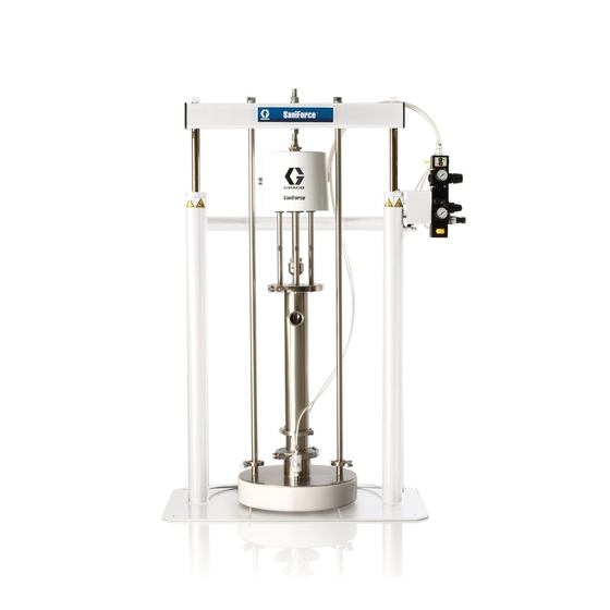
SaniForce
Ram Packages
For use in sanitary applications to transfer medium to high viscosity fluids.
For professional use only.
Not approved for use in European explosive atmosphere locations.
See page 2 for model information, including maximum fluid working pressure.
Important Safety Instructions
Read all warnings and instructions in this
manual and pump manual. Save all
instructions.
®
3A6980A
EN
Advertisement
Table of Contents

Related Manuals for Graco SaniForce


Summary of Contents for Graco SaniForce
- Page 1 Instructions/Parts ® SaniForce 3A6980A Ram Packages For use in sanitary applications to transfer medium to high viscosity fluids. For professional use only. Not approved for use in European explosive atmosphere locations. See page 2 for model information, including maximum fluid working pressure.
-
Page 2: Table Of Contents
Cleaning Procedure ..... 12 Graco Standard Warranty ....26 Troubleshooting . -
Page 3: Warnings
Warnings Warnings The following warnings are for the setup, use, grounding, maintenance, and repair of this equipment. The exclamation point symbol alerts you to a general warning and the hazard symbols refer to procedure-specific risks. When these symbols appear in the body of this manual, refer back to these Warnings. Product-specific hazard symbols and warnings not covered in this section may appear throughout the body of this manual where applicable. - Page 4 Warnings WARNING EQUIPMENT MISUSE HAZARD Misuse can cause death or serious injury. • Do not operate the unit when fatigued or under the influence of drugs or alcohol. • Do not exceed the maximum working pressure or temperature rating of the lowest rated system component.
-
Page 5: Installation
Installation Installation Grounding Solvent pails used when flushing: Follow local code. Use only conductive metal pails, placed on a grounded surface. Do not place the pail on a nonconductive surface, such as paper or cardboard, which interrupts grounding continuity. To maintain grounding continuity when flushing or The equipment must be grounded. -
Page 6: Setup
Connects the fluid system components and accessories. Contact your outlet hose to the pump fluid outlet. Graco distributor for assistance in designing a system to • Air Line Filter (K): Recommended for all systems. suit your particular needs. - Page 7 Installation Key: . 1: Typical Installation, Piston Pump Key: Ram Package Components (Supplied) Accessories (Required, not supplied) Pump Air Supply Hose (use 1/2 in. air hose, minimum) Air Line Filter Wiper Seal Bleed-Type Air Valve Pump Air Supply Fluid Outlet Hose Air Assist Air Supply Fluid Drain Valve (for pump) Ram Director Air Supply...
- Page 8 Installation . 2: Typical Installation, Diaphragm Pump Key: Ram Package Components (Supplied) Accessories (Required, not supplied) Pump Air Supply Hose (use 1/2 in. air hose, minimum) Air Line Filter Wiper Seal Bleed-Type Air Valve Pump Air Supply Fluid Outlet Hose Air Assist Air Supply Fluid Drain Valve (for pump) Ram Director Air Supply...
- Page 9 Installation Exposed Air Control Module Exposed Air Control Module (Rear View) (Front View) Pump Air Supply Air Motor Pressure Gauge Ram Up Air Supply Air Assist Air Supply Ram Down Air Supply Ram Air Pressure Gauge Main Air Inlet (on bottom) .
-
Page 10: Operation
Operation Operation Pressure Relief Procedure Starting and Adjusting the Ram This equipment stays pressurized until pressure is Remain clear of a moving ram to reduce risk of manually relieved. To help prevent serious injury from serious injury of crushing from moving parts. Keep pressurized fluid, such as splashing fluid and moving hands and fingers away from the ram plate, pump parts, follow the Pressure Relief Procedure when... -
Page 11: Starting And Adjusting The Pump
Operation Starting and Adjusting the Pump Changing Drums 1. Ensure the pump air motor regulator (BE) is closed. Set the ram air regulator (BB) to about 50 psi (3.5 Moving parts can pinch, cut, or amputate fingers and bar, 0.35 MPa). Set the ram director switch/valve other body parts. -
Page 12: Shutdown
Operation Shutdown 3. Set the director valve (BC) to UP to raise the ram. 4. If needed, use the air assist valve (BG) to help lift the ram plate. 5. Raise the ram until the ram plate is completely out of the drum. -
Page 13: Troubleshooting
Troubleshooting Troubleshooting 1. Follow the Pressure Relief Procedure, page 10. 2. Check all possible remedies in the Troubleshooting Chart before disassembling the pump. Problem Cause Solution Ram will not raise or lower. Closed air valve or clogged air line. Open, clear. Not enough ram air pressure. -
Page 14: Repair
Repair Repair Disconnect the Piston Pump Disconnect the Diaphragm Pump 1. Follow the Pressure Relief Procedure, page 10. 1. Follow the Pressure Relief Procedure, page 10. 2. Disconnect the (E). Air Assist Air Supply 2. Disconnect the (E). Air Assist Air Supply 3. -
Page 15: Service Ram Pistons
Repair Service Ram Pistons Always service both cylinders at the same time. When you service the piston rod, always install new o-rings in 121† the piston rod seal and ram piston. 115*† • Order Piston Repair Kit 24G853 for a stainless steel 122†... - Page 16 Repair Reassemble the Piston and Seal 6. Lubricate the o-ring (105) and piston seal housing (103). 1. Install new o-rings (105 and 110). Lubricate the piston (107) and o-rings. 7. Slide the spring (104) and piston seal housing (103) on the rod (102). Be careful not to push the piston 2.
-
Page 17: Notes
Repair Notes 3A6980A... -
Page 18: Parts
Parts Parts Piston Pump Ram † † † † 3A6980A... -
Page 19: Diaphragm Pump Ram
Parts Diaphragm Pump Ram † † † † 3A6980A... - Page 20 Parts Parts Ref. Part Description 24D630 FRAME, ram, assembly, includes piston assembly 16G477 TIE ROD 512743 WASHER, flat 18-8 sst 7/8 in. 510221 NUT, hex st sst 7/8-9 ----- RAM PLATE ASSEMBLY, See F 25E078 CONTROLS, air; see page 23 PUMP** 25M912 SP15.0080...
-
Page 21: Ram 24D630
Parts Ram 24D630 121† 122† 115† 105† 106† 111† 112† 104† 102* 105† 110† 109† 108† ti16273b 3A6980A... - Page 22 Parts Ram 24D630 Muffler Kit 16G390 Each side contains the following parts. Ref. Part Description Qty. 512914 MUFFLER, polyethylene Ref. Part Description Qty. Exhaust Assembly Kit 16G389 ----- RAM, frame 102* 16G478 ROD, piston, nickel-plated Ref. Part Description Qty. 16E383 BEARING 512914 MUFFLER, polyethylene 104†...
-
Page 23: Air Controls Kit
Parts Air Controls Kit Kit 16G396 Air Controls Carbon Steel, Exposed 301b Ref. Part Description Qty. ----- CONTROL, air, includes 301h 301a-301m 301d 301a ----- MANIFOLD 301b 121108 VALVE, shutoff 301c 121107 VALVE, control 301d 121110 O-RING 301e 301e ----- REGULATOR 301f 121106... -
Page 24: Dimensions
Dimensions Dimensions 49 in. (124.5 cm) 9 ft (2.75 m) when fully raised. 5 ft. 8 in. (1.73 m) when fully lowered. Four 0.562 in. (14 mm) mounting holes. 38 in. (96.5 cm) 21 in. (53.4 cm) 42 in. (106.7 cm) 25 in. -
Page 25: Technical Data
Technical Data Technical Data Maximum Fluid Working Pressure 6:1 Ratio Piston Pumps 650 (4.5 MPa, 44.8 bar) Diaphragm Pumps 120 (0.8 MPa, 8.2 bar) Maximum Package Air Inlet Pressure Piston Pump Ram Packages 100 psi (0.7 MPa, 6.9 bar) Diaphragm Pump Ram Packages 120 psi (0.8 MPa, 8 bar) Maximum Ram Air Inlet Pressure 100 psi (0.7 MPa, 6.9 bar) -
Page 26: Graco Standard Warranty
With the exception of any special, extended, or limited warranty published by Graco, Graco will, for a period of twelve months from the date of sale, repair or replace any part of the equipment determined by Graco to be defective.
Need help?
Do you have a question about the SaniForce and is the answer not in the manual?
Questions and answers