Graco Saniforce Operation
Sanitary tote unloader stu
Hide thumbs
Also See for Saniforce:
- Operation (60 pages) ,
- Manual (34 pages) ,
- Instructions - parts manual (26 pages)
Table of Contents
Advertisement
Quick Links
Operation
SaniForce® Sanitary Tote
Unloader (STU)
For use with food grade bulk supply of medium to high viscosity product. For professional use only. Only
select models are approved for use in explosive atmospheres or hazardous locations. See Configuration
Matrix on page 6 for more information.
Important Safety Instructions
Read all warnings and instructions in this manual and all related
manuals. Save all instructions.
For Maximum Working Air and Fluid
Pressures, see Models on page 8.
PROVEN QUALITY. LEADING TECHNOLOGY.
3A5416C
EN
Advertisement
Table of Contents

Subscribe to Our Youtube Channel
Related Manuals for Graco Saniforce


Summary of Contents for Graco Saniforce
- Page 1 Operation SaniForce® Sanitary Tote 3A5416C Unloader (STU) For use with food grade bulk supply of medium to high viscosity product. For professional use only. Only select models are approved for use in explosive atmospheres or hazardous locations. See Configuration Matrix on page 6 for more information.
-
Page 2: Table Of Contents
3A5999 SaniForce High Sanitation Diaphragm Pumps, Instructions and Parts 3A6781 SaniForce 1590 High Sanitation Diaphragm Pump, Repair and Parts 3A6782 SaniForce High Sanitation Diaphragm Pumps, Models 2150, 3150, 4150, Repair and Parts 3A1211 SaniForce Air Motors, Instructions and Parts 3A6101... -
Page 3: Warnings
Warnings Warnings The following warnings are for the setup, use, grounding, maintenance, and repair of this equipment. The exclamation point symbol alerts you to a general warning and the hazard symbols refer to procedure-specific risks. When these symbols appear in the body of this manual or on warning labels, refer back to these Warnings. - Page 4 Warnings WARNING SKIN INJECTION HAZARD High-pressure fluid from dispensing device, hose leaks, or ruptured components will pierce skin. This may look like just a cut, but it is a serious injury that can result in amputation. Get immediate surgical treatment. •...
- Page 5 Warnings WARNING EQUIPMENT MISUSE HAZARD Misuse can cause death or serious injury. • Do not operate the unit when fatigued or under the influence of drugs or alcohol. • Do not exceed the maximum working pressure or temperature rating of the lowest rated system component.
-
Page 6: Configuration Matrix
Configuration Matrix Configuration Matrix Check the identification plate (ID) for the Configuration Number of your system. Use the following matrix to define the components of your system. STU A01AAA1AA1C21 Sample Configuration Number: Sanitary Frame Pump Plate Size Seal Seal Controls Accessories Wash Kit Certification Tote (Bin Type) Type... - Page 7 Configuration Matrix Seal Material Controls Accessories Wash Kit Certification Polychloro- Enclosed Bag Clamp Kit None EN 10204 type 2.1 prene (White) Pneumatic Poly Tank Kit EPDM Electro- Aceptic Liner EN 10204 type 3.1 (Black) pneumatic Clamp Kit * Not ATEX. Not intended for use in explosive or hazardous environments. All models are rated and are FDA compliant.
-
Page 8: Models
Models Models Pump Max Pump Air Inlet Max Working Fluid Max System Air Max Control Air Inlet Option Pressure PSI (MPa, Pressure PSI (MPa, bar) Consumption scfm (m /min) Pressure PSI (MPa, bar) bar) 80 (0.55, 5.5) 410 (2.83, 28.3) 140 (3.9) 100 (0.69, 6.9) 100 (0.69, 6.9) -
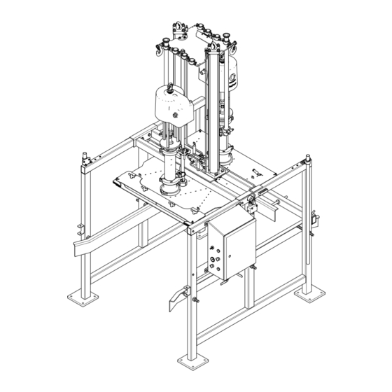
Page 9: Overview
Overview Overview System Components Fig. 1 Typical components 1–A Stainless Steel Frame: supports all of the system components. 1–B Sanitary Pumps: pump material from the tote to the target application. 3A5416C... - Page 10 Overview 1–C Air Cylinders: raises and lowers the pumps and the ram plate in and out of the material container. 1–D Ram Plate: applies an even amount of pressure to the material in the tote. When the ram plate seal is inflated, it creates a seal. The ram plate presses down on the material in the tote to assist the pumps in delivering the material.
-
Page 11: Before Installing
Before Installing Before Installing Palletized STU 3A5416C... -
Page 12: Uncrating Equipment
Do not force the NOTICE safety latch to disengage. It may be necessary to install this safety latch extension rod at a later Moving the SaniForce STU off the pallet without time. following this uncrating procedure can damage equipment. -
Page 13: Location
• Provides enough room on the right and/or left side STU is capable of exerting downward force of 2220 of the SaniForce STU to easily load and unload lbf (9.9 kN) which could cause the STU to lift off of fluid totes with a forklift or pallet jack hand truck. -
Page 14: Installation
Installation Installation Before operating the pump, ground the system as explained below. • Electro-pneumatic control panel: If installed, it is grounded through the grounding conductor of the incoming power wiring. All electrical wiring must be done by a qualified electrician and comply with all local codes and •... -
Page 15: Ac Power
Installation AC Power 3. Connect equipment to 100 – 240 VAC, single phase, 50/60 Hz, with a maximum 15 A branch circuit protection and disconnect switch provided AC power is required for an unloader with an by the installer. Use 14 AWG (2.0 mm ) stranded electro-pneumatic control panel. -
Page 16: Safety Latch
Safety Latch Safety Latch Safety Latch Lockout Lockout/tagout holes have been provided to lock the ram in the raised position. 1. Push the safety latch handle all the way in to align the lockout/tagout holes (Y). 2. Insert a padlock through the hole and lock in The overall system weighs about 2400-3400 lb. -
Page 17: Controls And Connections
Controls and Connections Controls and Connections Control Panel (Pneumatic) Part No. 25C578 Control Side View Component Panel 3A5416C... - Page 18 Controls and Connections Connection Side View Bottom View NOTE: When routing hoses for the air motor air the ram moves up and down. Select which hose supply, seal inflation, and air assist (blowoff) through support bracket hole to use for each specified hose the hose support bracket on the side of the frame, by observing where that hose will travel during most of the lengths of each hose must be able to...
- Page 19 Controls and Connections Ref. Symbol Description Ram Position Selector: Ram Up: Ram moves up. Up speed is regulated by flow control valve FC2. Up pressure is regulated by R4 (V). Ram Hold: Holds ram at intermediate position. Ram Down: Ram moves down and maintains force against top of product in tote. Down pressure is regulated by R3 (J).
- Page 20 Controls and Connections Ref. Symbol Description Seal Regulator: Controls the air pressure supplied to the inflatable seal. Ram Up Regulator: Controls the air pressure supplied to the cylinder for moving upward. — — — Seal Pressure Gauge: Indicates actual seal pressure. Pump Regulator: Controls the air pressure supplied to the pumps.
- Page 21 Controls and Connections Ref. Symbol Description — — — Cylinder Exhaust Port: Movement of ram plate will exhaust return side of the ram cylinders through this port. — — — Pump Pressure Dump Port: Whenever pumps are stopped, the air supply pressure to the pump distribution manifold and the pump air inlets is dumped through this port.
-
Page 22: Control Panel (Electro-Pneumatic)
Control Panel (Electro-Pneumatic) This panel is UL508A certified and requires using only Listed or Recognized components. Replacing parts with genuine Graco parts is important to Part No. 25D009 maintain this certification. See the parts manual for When supplied with 110–240 VAC power and a replacement part numbers. - Page 23 Controls and Connections Ref. Symbol Description Pump Air Supply Ports (3 provided): Connect supply air to pump manifold (FF) ports. Route hoses through the hose block on the side of the frame. Use the three provided 109 inch hoses. Connect the pump manifold (GG) ports to the pump air motors. Check valve pilot: Connect 3/8 in.
-
Page 24: Operation
Operation Operation Pressure Relief Procedure c. Either raise the ram to the top position and engage safety latch (see Engaging Safety Latch, page 16) or lower all Follow the Pressure Relief Procedure the way down. whenever you see this symbol. d. -
Page 25: Adjust Tote Guides
Operation Adjust Tote Guides c. Move the tote in front of the frame. d. Remove the lid from the fluid tote to expose the fluid bag. If present, open the outer plastic bag and pull it up over the sides of the tote, exposing the aseptic inner bag. -
Page 26: Start And Adjust The Pump
Operation Start and Adjust the Pump c. If the ram raises the tote off of the ground, press the air assist (blowoff) button to break the vacuum between the ram plate and 1. Load tote. See Loading the Tote, page product. -
Page 27: Emergency Stop
Operation Emergency Stop Flushing and Storage Manual control systems do not have this feature. The STU electro-pneumatic control box has an emergency stop button below the display screen. Pressing the emergency stop button will stop the pump but does not depressurize the system. Resetting the emergency stop places the system in a ready state. -
Page 28: Maintenance
Maintenance Maintenance Lubrication Cleaning the Pump Lower The pump is lubricated at the factory. It is designed to require no further lubrication for the life of the packings. There is no need to add an inline lubricator under normal operating conditions. Cleaning the Ram Plate NOTE: If the installed pumps are double diaphragm, this procedure does not apply. -
Page 29: Electro-Pneumatic Control Panel Display Screens
Electro-pneumatic Control Panel Display Screens Electro-pneumatic Control Panel Display Screens When the system is powered up, the Automatic run screen is displayed. The first time the unloader system is powered up, it will be necessary to perform system setup. See System Configuration Screen, page The display screen is a touch screen. - Page 30 Electro-pneumatic Control Panel Display Screens Specialty key definitions Description Exit Exit the keyboard or keypad. If the entry has not been saved, any displayed entry shown in the top field of the keyboard or keypad is lost. Backspace Erase the last character of the displayed entry in the top field of the keyboard or keypad. This key will erase one character each time it is pressed.
-
Page 31: Startup Screen
Electro-pneumatic Control Panel Display Screens Startup Screen When the power ON/OFF switch is turned ON, the display shows the startup screen while the system prepares the system for operation. 3A5416C... -
Page 32: Automatic Screen
Electro-pneumatic Control Panel Display Screens Automatic Screen Feedback enabled Feedback disabled NOTES: of the tote. If the ram plate is not below the rim of the tote when the start button is released, ram • To prime a full tote for automatic operation, press movement ceases. - Page 33 Electro-pneumatic Control Panel Display Screens Icon / Field Description Stop tote unloading. If the recipe is not complete, the tote unloading status is retained so that the recipe can be completed. If the desire is to stop the tote unload without completing, change over to manual mode to perform further operations to unload or remove the current tote.
-
Page 34: Manual Screen
Electro-pneumatic Control Panel Display Screens Manual Screen NOTES: • These buttons are disabled while the automatic sequence is operating. • Recipes which are locked will disable the pressure boxes from editing on this screen. Icon/Field Description Unit of measurement Defined by the value selected in the Pressure Units field on the System Settings screen. Current Recipe Name of the recipe selected for unloading this tote. - Page 35 Electro-pneumatic Control Panel Display Screens Icon/Field Description Pump Slow Press to begin tote unloading using a slow pump speed. Seal Control Seal Inflate Press to inflate the ram plate seal. Stop seal action Stop inflating or deflating the seal. To resume, press the desired seal action button, inflate or deflate.
-
Page 36: Recipe Screens
Electro-pneumatic Control Panel Display Screens Recipe Screens NOTES: • Recipes may use feedback from external devices Recipes define preset settings for unloader operation to determine when a specific measure of product when unloading defined products. If the STU will has been evacuated, so the system settings must be operated manually, it is not necessary to define be completed before any recipes are defined. - Page 37 Electro-pneumatic Control Panel Display Screens Material Recipe Screen Icon/Field Description Recipe # A numeric list of all available recipes. A maximum of 100 (0–99) recipes can be defined. Recipe Name User defined alphanumeric name. The maximum number of characters allowed, including spaces is 19.
- Page 38 Electro-pneumatic Control Panel Display Screens Material Recipe Edit Screen When creating a new recipe from scratch, default pressure settings will be pre-filled in. These pressures are offered as good starting points, but most will have to be varied to obtain optimal performance for the specific application.
- Page 39 Electro-pneumatic Control Panel Display Screens Icon/Field Description Pump Slow Pressure Select the air pressure desired to be applied to the pump when running in pump slow speed. Slow speed runs automatically when loading a new container of material to prime the pump, and at the very end of an empty container. Refer to the pump manual for minimum and maximum allowed pressures.
- Page 40 Electro-pneumatic Control Panel Display Screens Material Recipe Timers Screen Icon/Field Description Press to complete the fields of this recipe with the values assigned to another recipe. After copying, individual fields can be modified to differentiate this recipe from the one copied. The copied values will overwrite any defined values in this recipe.
- Page 41 Electro-pneumatic Control Panel Display Screens Container Recipe Screen Icon/Field Description Container Recipe # A numeric list of all available recipes. A maximum of 20 (0–19) recipes can be defined. Container Recipe User defined alphanumeric name. The maximum number of characters allowed, including spaces is 19.
- Page 42 Electro-pneumatic Control Panel Display Screens Container Recipe Edit Screen An empty tote will be required for defining the container recipe. Icon/Field Description Recipe Name User defined alphanumeric field, 19 characters maximum Recipe Locked When locked, the password defined on the System Settings page must be entered to edit the selected recipe.
- Page 43 Electro-pneumatic Control Panel Display Screens Icon/Field Description Ram Down Momentarily press to lower the ram to the lowest position. The ram will continue lowering until the ram has reached the bottom of its travel unless manually stopped. Set Container Top Position the tote and use the manual controls to lower the ram plate into the tote until the top lip of the ram plate is at the same height as the top lip of the tote.
-
Page 44: Event Log
Electro-pneumatic Control Panel Display Screens Event Log Events are Alarms, Deviations, Advisories, and Records detected by the system. They are logged to assist in troubleshooting the system. Alarms and Deviations will cause the unloader to cease evacuation when they are detected. A user will need to clear the alarm or deviation and restart the unloader. - Page 45 Electro-pneumatic Control Panel Display Screens ELECTRIC SHOCK HAZARD To reduce the risk of electric shock when accessing the electrical enclosure while power is present: • All electrical work must be done by a qualified electrician. • Wear appropriate personal protective equipment. Event Error Type...
- Page 46 Alarm Software Error WX00 Unexpected state detected in Acknowledge the alarm. If the alarm is the software triggered regularly, contact Graco Alarm X20AO2622 analog WMCA X20AO2622 module reports an Check X20AO2622 module and wiring. output module error error Verify that the modules are installed in the proper locations*.
-
Page 47: Job Log
Electro-pneumatic Control Panel Display Screens Job Log This screen will show the latest completed jobs, but user interaction is not currently available. 3A5416C... -
Page 48: System Configuration Screen
Electro-pneumatic Control Panel Display Screens System Configuration Screen The system configuration screen defines the STU parameters. Icon Description Import USB: Import the system settings from a flash drive. Export USB: Export the system settings to the flash drive. Shutdown/Depressurize: Press to vent pressure from the system. If the ram is not locked or held in place, it will move down as venting occurs. - Page 49 Electro-pneumatic Control Panel Display Screens Field Description Language Select the desired language. Date Format Select the desired date format. Date Enter the current date. Time Enter the current time. Password Enter the desired password to be used to access the control box display screens.
-
Page 50: Feedback Control Settings Screens
Electro-pneumatic Control Panel Display Screens Feedback Control Settings Screens No Feedback 3A5416C... - Page 51 Electro-pneumatic Control Panel Display Screens Feedback Control To reduce the risk of injury due to electric shock, remove power to the control panel before entering the control panel to make connections for measurement devices. Selecting scale feedback Selecting pulse feedback Icon/Field Description Feedback Type...
- Page 52 Electro-pneumatic Control Panel Display Screens Icon/Field Description Aux 1 Input Select input type: • None: No input enabled • Start/Stop: System runs while high signal (>16 VDC) is being received on CM8281-11. System pauses while no signal is present (<5 VDC) Aux 2 Input Select input type: •...
-
Page 53: About
Electro-pneumatic Control Panel Display Screens About The about screen displays the STU software information. 3A5416C... -
Page 54: I/O Status Screen
Electro-pneumatic Control Panel Display Screens I/O Status Screen Icon / Field Active Conditions Digital Inputs and Outputs Available settings: (flue) Asserted (yellow) Not asserted Pump fast Pump slow, pump fast Ram up Ram jog, ram down Seal inflate Air assist Seal deflate Aux 1 Aux 2... -
Page 55: Dimensions
Dimensions Dimensions K In. (cm) Lowest Highest (cm) (cm) (cm) (cm) In. (cm) (cm) (cm) (cm) In. (cm) Position Position 59.5 117.3 64.6 48.6 49 max. 76.5 6 (15.2) 3.2 (8.1) 50.8 (129) (151) (298) (164) (123) (124.5) (178) (194) (137) 3A5416C... -
Page 56: Schematic (Pneumatic Control)
Schematic (pneumatic control) Schematic (pneumatic control) 3A5416C... -
Page 57: Schematic (Electo-Pneumatic Control)
107PB E-STOP 1060 1070 LINE+ 108CP 24 VDC CIRCUIT PROTECTOR 2.0 AMP 1090 24 VDC LOAD+ I/O POWER LINE 125 1061 1060 GRACO HMI 4PPC70.070M-20F001 RDY/F OPS1 OPS2 OPS3 OPS4 OPS5 POWERLINK OP2 OP1 1060 1060 1150 1060 1090 1090... - Page 58 Schematic (electo-pneumatic control) BASE- X20BM11 TERMINAL BLOCK- X20TB12 MODULE- X20DS438A 1520 BLACK 1530 BLACK 1540 LASER SENSOR BROWN 1550 SHOP AIR PRESSURE BROWN NOT USED WHITE 1560 BLUE 1570 BLUE 1580 BLACK 1590 BLACK 1600 SEAL AIR PRESSURE BROWN 1610 PUMP AIR PRESSURE BROWN 1620...
- Page 59 Schematic (electo-pneumatic control) FROM LINE FROM LINE FROM LINE 1060 1061 1061 BASE- X20BM11 BASE- X20BM11 TERMINAL BLOCK- X20TB12 TERMINAL BLOCK- X20TB12 MODULE- X20DO8322 MODULE- X20AO2622 BLACK-2 BLACK-1 2270 2020 1061 WHITE PUMP FAST SOLENOID VALVE 1060 BROWN 1060 BROWN 1060 BLACK-2 BLACK-1 WHITE 2280...
- Page 60 Schematic (electo-pneumatic control) All components marked optional are devices not FROM LINE provided with the control panel and shall be provided 1060 1061 by the installer. BASE- X20BM11 TERMINAL BLOCK- X20TB12 All fittings and connections are coming out the bottom MODULE- X20CM8281 of the control panel.
- Page 61 Schematic (electo-pneumatic control) 3A5416C...
-
Page 62: Technical Data
Technical Data Technical Data SaniForce STU Metric Maximum working fluid pressure See pump manual Compressed air requirement 60-100 psi 0.41-0.7 MPa, 4.1-7 bar Pressure ratio See pump manual Air consumption See pump manual. Multiply by number of pumps Flow rate @ 60 cpm See pump manual. - Page 63 Technical Data Fluid Temperature Range NOTICE Temperature limits are based on mechanical stress only. Certain chemicals will further limit the fluid temperature range. Stay within the temperature range of the most-restricted wetted component. Operating at a fluid temperature that is too high or too low for the components of your pump may cause equipment damage.
- Page 64 With the exception of any special, extended, or limited warranty published by Graco, Graco will, for a period of twelve months from the date of sale, repair or replace any part of the equipment determined by Graco to be defective.
Need help?
Do you have a question about the Saniforce and is the answer not in the manual?
Questions and answers