Table of Contents
Advertisement
Quick Links
Instructions-Parts List
SaniForce
Bin Evacuation System
For use with 300 gallon (1135 liter) bags in bin containers. For professional use only.
Not approved to European Explosive Atmosphere requirements.
See page 3 for model information, including maximum working pressure and approvals.
Important Safety Instructions
Read all warnings and instructions in this
manual. Save these instructions.
™
311163ZAH
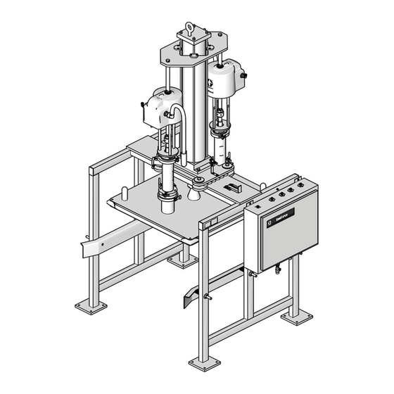
Model BESE1A Shown
ti16236a
EN
Advertisement
Chapters
Table of Contents

Related Manuals for Graco SaniForce BES Series


Summary of Contents for Graco SaniForce BES Series
- Page 1 Instructions-Parts List ™ SaniForce 311163ZAH Bin Evacuation System For use with 300 gallon (1135 liter) bags in bin containers. For professional use only. Not approved to European Explosive Atmosphere requirements. See page 3 for model information, including maximum working pressure and approvals. Important Safety Instructions Read all warnings and instructions in this manual.
-
Page 2: Table Of Contents
Air Motor Icing ......28 Graco Information ......64 Preventive Maintenance . -
Page 3: Models
Models Models Maximum Working Fluid Pressure, per pump Pump Part No., psi (MPa, bar) Part No. Qty. Pump Controls Approvals BESA7A, 410 (2.8, 28.3) 24G742 5:1 SaniForce Pump Electronic, Micrologix (2) BESA7F 410 (2.8, 28.3) 24G742 5:1 SaniForce Pump Electronic Contrologix (2) BESA1F 410 (2.8, 28.3) 24G742... - Page 4 Models 311163ZAH...
-
Page 5: Warnings
Warnings Warnings The following warnings are for the setup, use, grounding, maintenance, and repair of this equipment. The exclama- tion point symbol alerts you to a general warning and the hazard symbols refer to procedure-specific risks. When these symbols appear in the body of this manual, refer back to these Warnings. Product-specific hazard symbols and warnings not covered in this section may appear throughout the body of this manual where applicable. - Page 6 Warnings Warning EQUIPMENT MISUSE HAZARD Misuse can cause death or serious injury. • Do not operate the unit when fatigued or under the influence of drugs or alcohol. • Do not exceed the maximum working pressure or temperature rating of the lowest rated system component.
-
Page 7: Overview
The SaniForce BES consists of a frame, two or four 2. Using the control panel, the operator lowers the ram Graco pumps, ram plate with an inflatable seal, ram air plate on top of the material. cylinder, and a manual or electronic control panel. -
Page 8: System Components (Manual Control)
Overview System Components (Manual Control) See F . 1. Air Shutoff Valve: shuts off air to the pneumatic control panel (B). Stainless Steel Frame: supports the cardboard or collapsible bin. Sanitary Pumps: pump material from the bin to the target application. Manual Control Panel: contains pneumatic controls to regulate the air pressure to pump air Air Cylinder: raises and lowers the pumps and the... -
Page 9: System Components (Electronic Control)
Overview System Components (Electronic Control) See F . 2. • turn the pumps on or off • inflate or deflate the ram plate seal Stainless Steel Frame: supports the cardboard or • raise or lower the ram plate collapsible bin. •... -
Page 10: Before Installing
Provides easy and safe access to the air supply Uncrating Equipment shutoff valves and the pneumatic control panel. Graco recommends a minimum of 3 ft (0.91 m) of NOTICE open space in front of the panel. Moving the SaniForce BES off the pallet without follow- ing this uncrating procedure will damage equipment. -
Page 11: Installation
Installation Installation 3. Secure the air cylinder (4) to the frame (602) with Anchoring Frame the screws (20) and washers (19). See F . 4. 1. Remove bolts holding the frame (602) to the ship- 4. Install the air motor mounting plate (402), slipping ping pallet. - Page 12 Installation 405, 411 408, 409, TI16216a TI16234a . 4: Air Motor Mounting Plate (BESA7A shown) 11. Uncrate and mount pumps to the ram plate (502), 16. On the control panel, switch to the RAM UP posi- with outlets facing away from pneumatic control tion.
-
Page 13: Connecting Pump Output Hoses
Installation Connecting Pump Output Hoses NOTE: Two Pump System Includes: • The output hose(s) (supplied by others) should BESAxx, BESBxx, BESCxx, BESExx, already be installed, with riggings and supports, and BESFxx ready for connection to the 2 in. tri-clamp (412, sup- 2 in. -
Page 14: Grounding
Installation Air and fluid hoses: use only electrically conductive Grounding hoses with a maximum of 500 ft (150 m) combined hose length to ensure grounding continuity. Check the electri- cal resistance of your air and fluid hoses. If the total resistance to ground exceeds 29 megohms, replace the hose immediately. -
Page 15: Manual Stop (All Models)
Manual Stop (all models) Manual Stop (all models) Lockout A lockout has been provided to lock the plate in the raised position. The overall system weighs about 2400-3400 lb. (1089-1542 kg). To avoid injury, always set manual 1. Engage the manual stop. See Engaging. stop latch to Engage position when working under the plate. -
Page 16: Manual Control System
Manual Control System Manual Control System Part No. 15E523 Manual Control See F . 9. Ref. Key Switch/Button Name Operation Seal Inflate On/Off Switch to ON to inflate ram plate seal. Switch to OFF to deflate ram plate seal. Ram Plate Seal Pressure Gauge Displays Ram plate seal pressure. -
Page 17: Pressure Relief Procedure
1. Fill all the pumps packing nut/wet cups 1/3 full with a psi (kPa, bar) compatible lubricant if applicable. Refer to your SEAL INFLATE 7 (48, 0.5) pump manual for details. Do not use Graco Throat Max: 15 (103, 1.0) Seal Lubricant with a sanitary application. RAM UP 30 (207, 2.1) 2. -
Page 18: Standard Operation
Manual Control System 12. Use the ram plate handles to center the ram plate Standard Operation inside the bin. Be careful not to pinch the inflatable seal when it enters the bin. Loading the Bin When raising or lowering the ram plate, keep hands and body away from ram plate and bin lip. -
Page 19: Electronic Control System
Electronic Control System Electronic Control System Connecting Pneumatic Control Panel Air Lines Air supply to panel must be filtered, dry and capable of delivering a minimum of 100 scfm at 100 psi (0.7 MPa, 7 bar). Refer to the table below and the Pneumatic Diagrams, pages 57 and 58, to make the top and bottom panel connec- tions. -
Page 20: Installing Electronic Control Panel
Electronic Control System Installing Electronic Control Panel Discrete Devices 110 VAC • Locate the electronic control panel so the Manual Push Buttons operator has an unobstructed view of the Emergency Stop SaniForce BES to avoid starting equipment when Power other personnel could be injured. •... -
Page 21: Part No. 15H145, 15J902, And 17R641 Electronic Control Panel
Electronic Control System Part No. 15H145, 15J902, and 17R641 Electronic Control Panel Ref. Key Switch/Button Name Operation SEAL INFLATE Press to inflate ram plate seal RAM JOG Press button to slowly lower ram (by exhausting ram up air pressure). Generally used when guiding ram plate into bin or making system adjustments. -
Page 22: Proximity Switch
Electronic Control System Proximity Switch The low limit proximity switch (641) is located near the The system timer controls how long the pumps run at air cylinder (mounting plate (15) and can be adjusted to slow speed at the end of bin evacuation. After the time operate at different levels in the bin. -
Page 23: Setting Air Pressures
Electronic Control System Setting Air Pressures Ref. Function Regulator Setting psi (kPa, bar) Each system function has an associated air pressure. SEAL INFLATE 15 (103, 1.0) (Max.) Air pressure regulators are located in the pneumatic control bin. Set initial air pressures as shown in the table RAM UP 30 (207, 2.1) below. -
Page 24: Pressure Relief Procedure
1/3 full with a compatible lubricant. Refer to your 3. Enter the desired set point - Minimum Value: 000, pump manual for details. Do not use Graco Throat Maximum Value: 999. Example (300 = 30 sec). Seal Lubricant with a sanitary application. - Page 25 Electronic Control System Batch Mode Setup The electrical control cabinet is designed to operate optional batching functions. The batch mode will allow the user to control the operation of the ram unit flow meter output or pump stroke monitors. Additional equip- ment is required to operate in either of the batch modes.
-
Page 26: Standard Operation
Electronic Control System 7. Initial Startup Only: The frame has spring-loaded Standard Operation guides to stabilize the bin. Adjust the guides equally with the screws on all four sides of the bin. Leave NOTE: When raising and lowering the ram plate, make enough space between guides and bin to allow for sure there are no objects obstructing the unit. -
Page 27: System Shutdown
Electronic Control System Automatic Evacuation of the Bin 1. On the Operator Interface, select TAR- GET/ACTUAL RUN screen. TARGET 1000 LBS ACTUAL 0000 LBS EXIT Press arrow to select RUN and press ENT. 2. Ram plate seal inflates. 3. Ram down air pressure is applied and pumps start in slow mode, then switches to fast mode. -
Page 28: Maintenance
Maintenance Maintenance To flush the system: Air Motor Icing 1. Load a bin containing water, compatible solvent, or Air motor icing occurs when moisture in the compressed cleaning solution that can dissolve the material and air collects in the air motor and freezes, causing the clean the system. -
Page 29: Cleaning Ram Plate And Seal
Maintenance Cleaning Ram Plate and Seal 1. Follow the Pressure Relief Procedure, page 17 or page 24. Keep the air supply to the ram open. 2. Raise the ram plate. To avoid injury, always set manual stop latch to Engage position when working under the plate. 3. -
Page 30: Troubleshooting
Troubleshooting Troubleshooting Problem Cause Solution Ram plate will not raise or Air pressure to the ram is too Increase RAM UP air pressure. lower. low. Ram plate is stuck in bin. 1. Deflate seal. Turn SEAL INFLATE to OFF. 2. Switch to RAM UP position. When it is raised, check for obstructions in bin or quality of seal. -
Page 31: Service
Service Service NOTE: See F . 16. All models do not use the same Replacing Cylinder Bearing parts. Refer to parts drawing for your model. (All Models) Before Servicing NOTICE To avoid damaging equipment, replace each bearing individually. Do not remove all four bearings at the same time. -
Page 32: Replacing Ram Plate Seal Or Corner Seals (All Models)
Service 4. Remove the ram plate seal (501), using a blunt-end Replacing Ram Plate Seal or tool to avoid damaging the seal. Carefully disen- Corner Seals (All Models) gage the air stem from the hole in the ram plate (502). See F . -
Page 33: Replacing Proximity Switch (Electronic Control Models Only)
Refer to F . 17. NOTE: Graco recommends 1/4 in. (6.35 mm) space between switch and plate (15). 3. Disconnect the cable from the switch (641). 4. Remove the two screws, lock washers, and the switch. -
Page 34: Saniforce Bes Pump Matrices
3150 Ball Check Arena Electronic BES4A1 3150 Flapper Check Arena Electronic BES8B3 3150 3A Ball Check Pallecon Manual BES3F3 3150 3A Ball Check GoodPak MB5 Manual Contact your Graco distributor if you require a configuration that is not listed. 311163ZAH... -
Page 35: Pumps
12:1, 4 pumps Manual BESFBD 12:1, 4 pumps Goodpack MB5/GPS1 Manual BESFFJ 12:1, 4 pumps Buckhorn Electronic, Contrologix, 2 Ethernet ports BESGBC 3150, 2 pumps Goodpack MB5/GPS1 Manual *Contact your Graco distributor if you require a configuration that is not listed. 311163ZAH... -
Page 36: Saniforce Bes Common Parts
SaniForce BES Common Parts SaniForce BES Common Parts Ref. Ref. Part No. Description Part No. Description C78216 CLAMP, ty-rap 15K301 CYLINDER, air; sst 111265 LUBRICANT, tube (not shown) 590570 TUBE, polyethylene; 1/2 in. (35 ft) 949412 CLAMP, bag (not shown); not used 514334 NUT;... -
Page 37: Saniforce Bes Common Parts (Besa7A Shown)
SaniForce BES Common Parts SaniForce BES Common Parts (BESA7A shown) TI16217a See page 35 See page 47 62 61 Detail of Manual Stop 51 See page 46 See pages 38-45 TI16216a See page 46 TI16237a 311163ZAH... -
Page 38: Pump Modules
Pump Modules Pump Modules Models 24G560 and 24G968, 5:1 SaniForce Double Ball Pump Module (2 Pumps) 409, 410 405, 411 412, 413 406, 407 TI16539a TI16538a TI16540a Ref. Ref. Part No. Description Qty. Part No. Description Qty. 500984 CLAMP, 2 in. tri-clamp 24G742 PUMP, 5:1 SaniForce;... -
Page 39: Model 24P829, 5:1 Saniforce Priming Piston Pump Module (2 Pumps)
Pump Modules Model 24P829, 5:1 SaniForce Priming Piston Pump Module (2 Pumps) 409, 410 405, 411 Ti20070b 412, 413 406, 407 Ti20068b Ti20069b Ref. Ref. Part No. Description Qty. Part No. Description Qty. 500984 CLAMP, 2 in. tri-clamp 24R233 PUMP, 5:1 SaniForce; 512332 GASKET, S-clamp;... -
Page 40: Model 24G561, 5:1 Saniforce Double Ball Pump Module (4 Pumps)
Pump Modules Model 24G561, 5:1 SaniForce Double Ball Pump Module (4 Pumps) 409, 410 405, 411 412, 413 406, 407 TI16543a TI16541a TI16542a Ref. Part No. Description Qty. Ref. Part No. Description Qty. 412 500984 CLAMP, 2 in. tri-clamp 401 24G742 PUMP, 5:1 SaniForce; 413 512332 GASKET, S-clamp;... -
Page 41: Model 24P815, 6:1 Saniforce Priming Piston Pump Module (2 Pumps)
Pump Modules Model 24P815, 6:1 SaniForce Priming Piston Pump Module (2 Pumps) 409, 410 405, 411 412, 413 406, 407 Ti20998a TI20997a TI20996a Ref. Ref. Part No. Description Qty. Part No. Description Qty. 118598 CLAMP, 1.5 in. tri-clamp 24D659 PUMP, 6:1 SaniForce; 16D169 GASKET, buna-N see manual 3A0733 -----... -
Page 42: Model 249488, 24E441, And 24C125 3150 Saniforce Ball Check Pump Module (2 Pumps)
Pump Modules Model 249488, 24E441, and 24C125 3150 SaniForce Ball Check Pump Module (2 Pumps) 409, 410 405, 411 249488 front 249488 side 249488 iso 406, 407 Qty. Qty. Ref. Part No. Description Ref. Part No. Description 412 512684 NUT, 3/4-10 Nylock 401 248273 PUMP, sanitary SaniForce, ball check;... -
Page 43: Model 249489 3150 Saniforce Flapper Check Pump Module (2 Pumps)
Pump Modules Model 249489 3150 SaniForce Flapper Check Pump Module (2 Pumps) 409, 410 405, 411 249489 front 249489 side 249489 iso 406, 407 Ref. Part No. Description Qty. Ref. Part No. Description Qty. 411 551364 WASHER, lock; 3/4 in.; sst 401 248274 PUMP, sanitary SaniForce, flap- 412 512684 ELBOW;... -
Page 44: Model 24G564 And 24G969 12:1 Saniforce Priming Piston Pump Module (2 Pumps)
Pump Modules Model 24G564 and 24G969 12:1 SaniForce Priming Piston Pump Module (2 Pumps) 405, 411 409, 410 412, 413 406, 407 TI16239a TI16240a TI16241a Ref. Part No. Description Qty. Ref. Part No. Description Qty. 410 170772 WASHER, plain 401 24F625 PUMP, 12:1 SaniForce; see 411 551364 WASHER, lock;... -
Page 45: Part No. 24G566, 24G970, And 26C040 12:1 Saniforce Priming Piston Pump Module (4 Pumps)
Pump Modules Part No. 24G566, 24G970, and 26C040 12:1 SaniForce Priming Piston Pump Module (4 Pumps) 409, 410 405, 411 412, 413 406, 407 TI16243a TI16244a TI16242a Ref. Part No. Description Qty. Ref. Part No. Description Qty. 170772 WASHER, plain 24F625 PUMP, 12:1 SaniForce;... -
Page 46: Inflatable Seal, Plate, Frames, And Controls
Inflatable Seal, Plate, Frames, and Controls Inflatable Seal, Plate, Frames, and Controls Electronic Inflatable Controls Proximity (Ref. 624 Seal* Plate Frame Controls Switch (Ref. 501) (Ref. 502) (Ref. 602) (Ref. 603) and 625)) (Ref. 631) (Ref. 641) Model 551413 17V159 15E339 949949 15J902... - Page 47 Inflatable Seal, Plate, Frames, and Controls Part No. 15E523, 2 Pump Manual Control Panel PUMP 1 RAM UP PUMP 2 RAM DOWN AIR IN Ref. Ref. Part No. Description Qty. Part No. Description Qty. 12†* 16V728 SWITCH, pneumatic, 2 position ----- ENCLOSURE, with back panel 13†...
- Page 48 Inflatable Seal, Plate, Frames, and Controls Part No. 15E523, 2 Pump Manual Control Panel, Pneumatic Diagram SCHEMATIC RAM UP RAM DOWN AIR IN PUMP 1 PUMP 2 SEAL 311163ZAH...
- Page 49 Inflatable Seal, Plate, Frames, and Controls Part No. 15M343, 4 Pump Manual Control Panel ti12839b Ref. Ref. Part No. Description Part No. Description 12† ----- BULKHEAD, 1/2 npt FBE ----- ENCLOSURE, control 13† ----- BULKHEAD, 1/2 npt(f) x 1/2 tod ----- SUBPLATE 14†...
- Page 50 Inflatable Seal, Plate, Frames, and Controls Part No. 15M343, 4 Pump Manual Control Panel, Pneumatic Diagram 311163ZAH...
- Page 51 Inflatable Seal, Plate, Frames, and Controls Part No. 949949, 2 Pump Pneumatic Control Panel Detail K Detail D Detail F Detail G 108, 110, Detail A Detail B ti10507b Detail B 119, 120 Detail J Detail H 22, 51 Detail E Detail C Detail K Detail J...
- Page 52 Inflatable Seal, Plate, Frames, and Controls Part No. 949949, 2 Pump Pneumatic Control Panel Ref. Ref. Part No. Description Qty. Part No. Description Qty. 598141 FITTING, tee, air; 5/32 x 1/8 npt 598140 FITTING, elbow; 5/32 in. tube x 103831 SCREW; 10-32 UNF 1/8 npt(m) 512912 MUFFLER, polyethylene 598095 TUBE, nylon;...
- Page 53 Inflatable Seal, Plate, Frames, and Controls Part No. 570193, 4 Pump Pneumatic Control Panel Detail K Detail G Detail F Detail C 51, 22 108, 110, 111 Detail A Detail B ti10506b Detail J 119, 120 Detail H Detail E 22, 51 Detail D Detail B...
- Page 54 Inflatable Seal, Plate, Frames, and Controls Part No. 570193, 4 Pump Pneumatic Control Panel Ref. Ref. Part No. Description Qty. Part No. Description Qty. 598141 FITTING, tee, air; 5/32 x 1/8 npt 598140 FITTING, elbow; 5/32 in. tube x 103831 SCREW; 10-32 UNF 1/8 npt(m) 512912 MUFFLER, polyethylene 598095 TUBE, nylon;...
- Page 55 Inflatable Seal, Plate, Frames, and Controls Common Parts for 570193 and 949949 Pneumatic Control Panels ti10494a ti10493a ti10500a Detail C Detail D ti10499a 38 112 67 9 ti10496a ti10505a ti10497a Detail E 311163ZAH...
- Page 56 Inflatable Seal, Plate, Frames, and Controls Common Parts for 570193 and 949949 Pneumatic Control Panels ti10481a ti10483a ti10482a Detail F ti10484a ti10485a ti10486a Detail G 25 24 ti10489a ti10488a Detail H ti10491a 311163ZAH...
- Page 57 Inflatable Seal, Plate, Frames, and Controls Part No. 949949 Pneumatic Control Panel, Pneumatic Diagram 94994902 311163ZAH...
- Page 58 Inflatable Seal, Plate, Frames, and Controls Part No. 570193 Pneumatic Control Panel, Pneumatic Diagram 570193_9 311163ZAH...
- Page 59 Inflatable Seal, Plate, Frames, and Controls Wiring Guide Electrical Control Cabinet Pneumatic Control Cabinet Wire Description Wire Color Wire Color Amphenol Description Wire 2040 +24 Vdc Black Black +24 Vdc 2042 Common White White Common Bin Empty Proximity Orange/red Orange/red Bin Empty Proximity Seal Power Supply White/red...
-
Page 60: Dimensions
Dimensions Dimensions System (BESA7A Shown) Front View Top View 6.0 in. (0.15 m) 50.6 in. (1.28 m) 60 in. (1.52 m) †118.8 in. (3.0 m) 40 in. (1.02 m) 58.3 in. 47 in. (1.48 m) (1.19 m) 0.56 in. 69 in. (14.3 mm) (1.75 m) 4 holes per... - Page 61 Dimensions System (BES3F3 Shown) Front View 118.8 in. (3.0 m) Top View 6.0 in. (0.15 m) 50.6 in. (1.28 m) 58.3 in. 60 in. (1.48 m) (1.52 m) 40 in. (1.02 m) ti16218a 47 in. (1.19 m) 0.56 in. (14.3 mm) 69 in.
-
Page 62: Technical Data
Technical Data Technical Data BES3xx, BES4xx, BES8xx, and BESGBC U.S. Metric Maximum Working Fluid Pressure 120 psi 8.4 bar, 0.84 MPa Compressed air requirement 80-120 psi 5.5-8.4 bar, 0.55-0.84 MPa Fluid displacement (each pump) 1.03 gal/cycle 3.9 l/cycle Flow rate @ 60 cpm 120 gpm 454 lpm Pressure ratio... -
Page 63: Besaxx, Besbxx, Bescxx, Besdxx, Besexx, And Besfxx
Technical Data BESAxx, BESBxx, BESCxx, BESDxx, BESExx, and BESFxx U.S. Metric Compressed air requirement 80-100 psi 5.5-7 bar, 0.55-0.7 MPa Sound data See your pump manual. Wetted parts 300 Series stainless steel, buna-N, and EPDM on the ram plate and seals. See your pump manual for additional wetted parts. -
Page 64: Graco Standard Warranty
With the exception of any special, extended, or limited warranty published by Graco, Graco will, for a period of twelve months from the date of sale, repair or replace any part of the equipment determined by Graco to be defective.
Need help?
Do you have a question about the SaniForce BES Series and is the answer not in the manual?
Questions and answers