Moxa Technologies DA-661 Hardware User Manual
Hide thumbs
Also See for DA-661:
- Quick installation manual (2 pages) ,
- Hardware user manual (18 pages)

Related Manuals for Moxa Technologies DA-661


Summary of Contents for Moxa Technologies DA-661
- Page 1 DA-661/662/663 Hardware User’s Manual Fifth Edition, April 2009 www.moxa.com/product © 2009 Moxa Inc. All rights reserved. Reproduction without permission is prohibited.
- Page 2 DA-661/662/663 Hardware User’s Manual The hardware described in this manual is furnished under a license agreement and may be used only in accordance with the terms of that agreement. Copyright Notice Copyright © 2009 Moxa Inc. All rights reserved. Reproduction without permission is prohibited.
-
Page 3: Table Of Contents
Package Checklist ........................1-2 Product Features ........................1-3 Hardware Specifications ......................1-3 Chapter 2 Hardware Introduction.................2-1 Appearance ..........................2-2 DA-661 ......................... 2-2 DA-662/DA-662-I ......................2-2 DA-663 ......................... 2-3 Dimensions ..........................2-3 DA-661/662/663......................2-3 DA-662-I ........................2-4 Hardware Block Diagram ......................2-4 DA-661 ......................... -
Page 4: Chapter 1 Introduction
PCMCIA socket, and 2 USB hosts based on the Intel XScale IXP425 communication processor. In addition, the DA-661 has two Ethernet ports, the DA-662 has 4 Ethernet ports, and the DA-663 has 2 fiber Ethernet channels. The casing is a standard 1U, 19-inch wide rack-mounted rugged enclosure. -
Page 5: Overview
PCMCIA socket, and 2 USB hosts based on the Intel XScale IXP425 communication processor. In addition, the DA-661 has two Ethernet ports, the DA-662 has 4 Ethernet ports, and the DA-663 has 2 fiber Ethernet channels. The casing is a standard 1U, 19-inch wide rack-mounted rugged enclosure. -
Page 6: Product Features
DA-661/662/663 Hardware User’s Manual Introduction Product Features Intel XScale IXP425 533 MHz Processor On-board 128 MB RAM, 32 MB Flash ROM 16 RS-232/422/485 serial ports 2 KV optical isolation protection for serial ports (DA-662-I only) 2 10/100 Mbps Ethernet (4 10/100 Mbps Ethernet for DA-662 model) - Page 7 100 to 240 VAC Power DA-661/662/663: 15W DA-662-I: 23.5W DA-661/662/663: 480 × 198 × 45 mm (with rack-mount ears) Dimension (W × D × H) 440 × 198 × 45 mm (without rack-mount ears) DA-662-I: 480 × 224 × 45 mm (with rack-mount ears) 440 ×...
-
Page 8: Chapter 2 Hardware Introduction
Hardware Introduction Chapter 2 DA-661/662/663 Series hardware is compact, well-designed, and built rugged for industrial applications. LED indicators help you monitor the performance and identify trouble spots. Multiple ports allow the connection of different devices for wireless operation. With the reliable and stable hardware platform that is provided, you may devote your attention to the development of your application. -
Page 9: Appearance
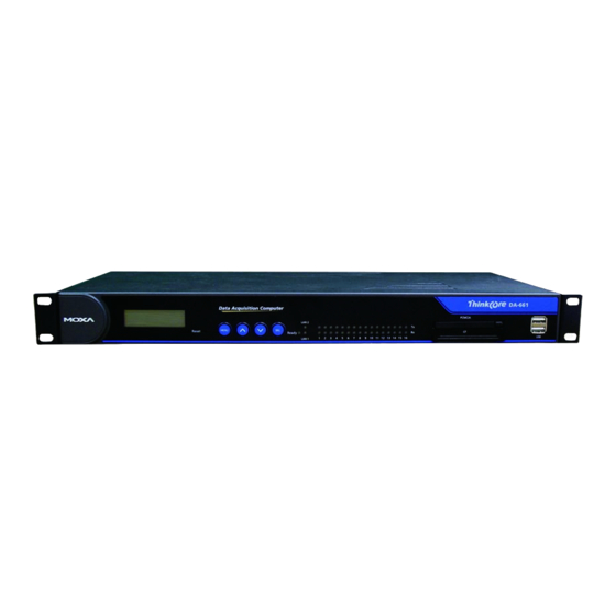
DA-661/662/663 Hardware User’s Manual Hardware Introduction Appearance DA-661 Front View LED Indicators System Status, LAN, Serial Tx/Rx LCM Display Panel PCMCIA Socket USB Host Push Buttons 19-inch Rackmount Ear Reset Button CF Socket Rear View Power Input 100-240 VAC/VDC RS-232 Console Port... -
Page 10: Dimensions
DA-661/662/663 Hardware User’s Manual Hardware Introduction DA-663 Front View LED Indicators System Status, LAN, Serial Tx/Rx LCM Display Panel PCMCIA Socket USB Host Push Buttons 19-inch CF Socket Reset Button Rackmount Ear Rear View Power Input RS-232 Console Port 100-240 VAC/VDC... -
Page 11: Hardware Block Diagram
Console LAN1 LAN2 100-240 VAC/VDC LAN3 440 mm (17.3") 480 mm (19") Hardware Block Diagram The following block diagrams show the layout of the DA-661/662/663’s internal components. DA-661 Ethernet PCMCIA & CF Console LAN2 LAN1 Power Host PCI to Cardbus... - Page 12 DA-661/662/663 Hardware User’s Manual Hardware Introduction DA-662/DA-662-I Ethernet PCMCIA & CF Console Power Host PCI to Cardbus Controller Bridge Power XScale IXP425 533 MHz circuit 32 MB Flash PCI Bus 128 MB SDRAM LCM Display & Keypad Moxa UART ASIC...
-
Page 13: Led Indicators
DA-661/662/663 Hardware User’s Manual Hardware Introduction LED Indicators LED indicators are located on the front panel of the DA-661/662/663. LED Name LED Color LED Function Ready Power is On, and system is ready (after booting up) Orange 10 Mbps Ethernet connection... -
Page 14: Lcd Screen
LCD Screen The DA-661/662/663 has an LCD screen on the front panel. The LCD screen can display 16 columns and 2 rows of text. After the DA-661/662/663 boots up, the LCD screen will display the model name and firmware version: Push Buttons There are four push buttons on the DA-661/662/663’s front panel. -
Page 15: Hardware Connection Description
Hardware Connection Description Chapter 3 This chapter covers the following topics: Placement Options Desktop Connecting the Power Connecting the Hardware Wiring Requirements Connecting the Power Connecting to the Network Connecting to a Serial Device Connecting to the Console Port PCMCIA CompactFlash USB Host... -
Page 16: Placement Options
L-shaped metal plates and screws to fasten your DA-661/662/663 to the rack cabinet. Two placement options are available. You can either lock the front or the rear panel of the DA-661/662/663 to the front of the rack. Each L-shaped plate has 6 holes, leaving two outer or inner holes open for your convenience. -
Page 17: Connecting The Power
DA-661/662/663’s AC power connector. The power connector is located on the right side of the rear panel. Next, turn on the power switch. The DA-661/662/663 takes about 30 seconds to boot up. Once the device is ready, the Ready LED on the front panel will light up, and the DA-661/662/663 model name and firmware version will appear on the LCD screen. -
Page 18: Connecting To A Serial Device
Connecting to the Console Port The DA-661/662/663’s console port is an 8-pin RJ45 RS-232 port. The port can be used to connect to the console utility from a remote console via a V90 or GPRS modem with PPP protocol. The pin definition is the same as for the serial ports (P1 to P16).
Need help?
Do you have a question about the DA-661 and is the answer not in the manual?
Questions and answers