Moxa Technologies DA-660-8-CE Quick Installation Manual
Hide thumbs
Also See for DA-660-8-CE:
- User manual (58 pages) ,
- Quick installation manual (2 pages) ,
- User manual (31 pages)
Advertisement
Quick Links
DA-660-8/16-CE
Quick Installation Guide
Third Edition, April 2009
1. Overview
DA-660 products are RISC-based ready-to-run embedded computers
designed for industrial data acquisition applications. They feature 8 or 16
RS-232/422/485 serial ports and dual Ethernet ports based on the Intel
XScale IXP422 communication processor. The casing is a standard 1U,
19-inch wide rack-mounted rugged enclosure. This robust,
rack-mountable mechanism design provides the hardened protection
needed for industrial environment applications, and lets users easily
install DA-660 on a standard 19-inch rack. Using DA-660, you can easily
build a control system with distributed architecture for embedded
technologies, such as SCADA systems, plant floor automation, and power
electricity monitoring applications.
2. Package Checklist
Before installing DA-660, verify that the package contains the following
items:
1 DA-660
19-inch Rackmount Kit
DA-660 Quick Installation Guide (this guide)
DA-660 Document & Software CD
Cross-over Ethernet cable
CBL-RJ45M9-150: 150 cm, 8-pin RJ45 to DB9 (M) serial port cable
CBL-RJ45F9-150: 150 cm, 8-pin RJ45 to DB9 (F) console port cable
Power Cord
Product Warranty Booklet
Notify your sales representative if any of the above items is missing or
damaged.
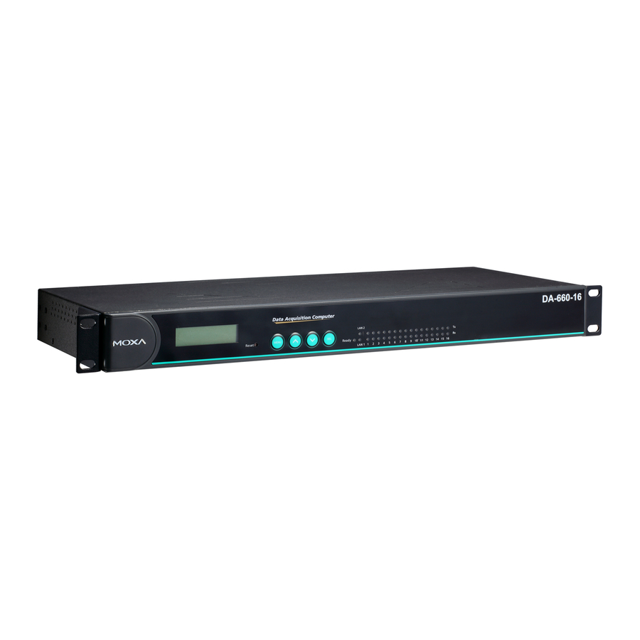
3. DA-660 Panel Layout
NOTE: Two models of DA-660 are available. DA-660-16 has 16
RS-232/422/485 serial ports and DA-660-8 has 8 RS-232/422/485 serial
ports.
P/N: 1802006601012
— 1 —
Front View
LED Indicators
LCM Display Panel
System Status, LAN, Serial Tx/Rx
Push Buttons
19-inch Rackmount Ear
Reset Button
Rear View
100-240 VAC/VDC
RS-232 Console Port
LAN2
RS-232/422/485
9
1 0
11
1 2
1 3
1 4
1 5
1 6
Console
1
2
3
4
5
6
7
8
LAN1
RS-232/422/485 Serial Ports x 8 (or 16)
10/100 Mbps Ethernet
RJ45, 50 bps to 921.6 Kbps
RJ45 x 2
LED Indicators
The following LED indicators are located on the front panel of the
DA-660.
LED Name
LED Color
LED Function
Ready
Green
Power is on and functioning normally.
Orange
10 Mbps Ethernet connection
LAN1-2
Green
100 Mbps Ethernet connection
Green
Serial port is transmitting data.
P1-P16 (Tx)
Off
Serial port is not transmitting data.
Orange
Serial port is receiving data.
P1-P16 (Rx)
Off
Serial port is not receiving data.
4. Installing Your DA-660
Desktop Mounting
Place your DA-660 on a clean, flat, well-ventilated desktop. For better
ventilation, attach the 4 pads from the desktop kit to the bottom of the
unit, and leave some space between the DA-660 and other equipment. Do
not place equipment or objects on top of the unit, as this can cause
damage to the product.
Rack Mounting.
DA-660 can be mounted on a standard 19-inch rack. Use the enclosed
pair of L-shaped metal plates and screws to fasten your DA-660 to the
rack cabinet. Two options are available. You can lock either the front or
the rear panel of the DA-660 to the front side of the rack. Each L-shaped
plate has 6 holes, leaving two outer or inner holes open for other uses.
5. Connecting Your
Power Connector
Connect the 100-240 VAC/VDC power line to DA-660's power
connector. If the power is properly supplied, the Ready LED on the front
panel will glow a solid green when the OS is ready.
Ethernet Port
The two 10/100 Mbps Ethernet ports (LAN 1 and LAN 2) use RJ45
connectors.
— 2 —
Pin
1
2
3
6
Serial Port
There are eight serial ports (P1 to P8) on DA-660-8 and 16 ports on
DA-660-16. All serial ports use RJ45 connectors. Each port can be
Power Input
configured by software as type RS-232, RS-422, or RS-485. The pin
assignments are shown in the following table:
Power Input
Pin
100-240 VAC/VDC
1
ON/OFF Switch
2
3
4
5
6
7
8
Console Port
The console port is an RJ45 RS-232 port. It can be connected to a V90 or
GPRS modem via PPP. The pin definitions are the same as for the serial
ports.
Reset Button
Press the "Reset" button on the front panel continuously for at least 5
seconds to load the factory default configuration. After the factory default
configuration has been loaded, the system will reboot automatically. The
Ready LED will blink for the first 5 seconds, and then maintain a steady
glow once the system has rebooted.
LCM Screen
DA-660 has an LCM screen on the front panel. The LCM can display 16
columns and 2 rows of text. After the DA-660 successfully boots up, the
LCM will display the model name and firmware version as shown:
D
A
V
E
Push Buttons
There are four push buttons on the DA-660's front panel. These buttons
are used to operate the LCM. Going from left to right, the buttons are:
Button Action
MENU Displays the main menu at any time.
︽
︾
SEL
Signal
ETx+
1
8
ETx-
ERx+
ERx-
RS-232
RS-422
RS-485
DSR
---
---
RTS
TXD+
---
GND
GND
GND
TXD
TXD-
---
RXD
RXD+
Data+
DCD
RXD-
Data-
CTS
---
---
DTR
---
---
-
6
6
0
-
1
6
R
.
1
.
0
Scrolls up through a list of items shown on the LCM screen's
second line
Scrolls down through a list of items shown on the LCM
screen's second line
Selects the option listed on the LCM screen.
— 3 —
1
8
Advertisement

Related Manuals for Moxa Technologies DA-660-8-CE


Summary of Contents for Moxa Technologies DA-660-8-CE
- Page 1 Front View Signal LED Indicators ETx+ LCM Display Panel System Status, LAN, Serial Tx/Rx ETx- ERx+ DA-660-8/16-CE ERx- Quick Installation Guide Push Buttons 19-inch Rackmount Ear Serial Port Reset Button There are eight serial ports (P1 to P8) on DA-660-8 and 16 ports on Rear View DA-660-16.
- Page 2 <DNS server>] [-g <gateway>] [-i <IP address>] Real Time Clock 7. Write your application code. For example, let us assume your development workstation has a LAN 8. From the Build menu, choose Rebuild All to build the application. DA-660’s real time clock is powered by a lithium battery. We strongly port at 192.168.1.x and the Domain Name Server (DNS) is at 192.168.2.6.
Need help?
Do you have a question about the DA-660-8-CE and is the answer not in the manual?
Questions and answers