
Subscribe to Our Youtube Channel
Related Manuals for Moxa Technologies DA-660A Series


Summary of Contents for Moxa Technologies DA-660A Series
- Page 1 DA-660A Series Hardware User’s Manual Version 2.1, June 2021 www.moxa.com/product © 2021 Moxa Inc. All rights reserved.
- Page 2 DA-660A Series Hardware User’s Manual The software described in this manual is furnished under a license agreement and may be used only in accordance with the terms of that agreement. Copyright Notice © 2021 Moxa Inc. All rights reserved. Trademarks The MOXA logo is a registered trademark of Moxa Inc.
-
Page 3: Table Of Contents
Table of Contents Introduction ............................1-1 Overview ............................1-2 Package Checklist ..........................1-2 Product Features ..........................1-2 Hardware Specifications ........................1-3 Hardware Introduction ........................2-1 Appearance ............................2-2 DA-662A-8 Models ........................2-2 DA-662A-16 Models ........................2-2 Dimensions ............................2-3 Hardware Block Diagram ........................2-3 DA-662A-8 Models ........................ -
Page 4: Introduction
Introduction The DA-660A Series embedded computers come with 8 to 16 software selectable RS-232/422/485 serial ports, making them suitable for a variety of industrial applications. Models with 4 10/100 Mbps Ethernet ports are also available. The DA-660A also comes with CF and USB ports to make it easy to add additional storage space. -
Page 5: Overview
DA-660A on a standard 19-inch rack. The DA-660A Series computers are ideal for applications that require a distributed embedded technology, such as SCADA systems, plant floor automation, and power electricity monitoring applications. -
Page 6: Hardware Specifications
DA-660A Series HW UM Introduction Hardware Specifications NOTE The latest specifications for Moxa’s products can be found at https://www.moxa.com. -
Page 7: Hardware Introduction
Hardware Introduction The DA-660A Series hardware is compact, well-designed, and built for rugged industrial applications. LED indicators help you monitor the performance and identify trouble spots. Multiple ports allow the connection of different devices for wireless operation. With the reliable and stable hardware platform that is provided, you can devote your attention to the development of your application. -
Page 8: Appearance
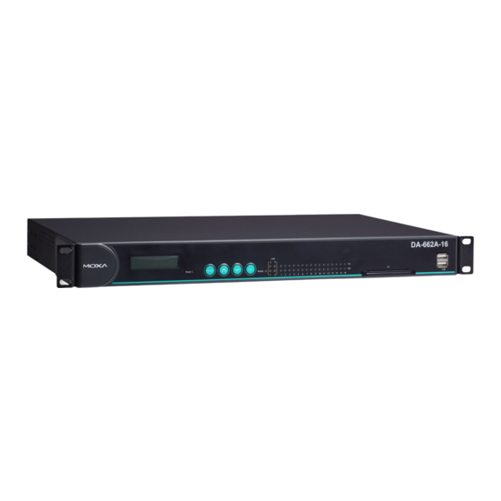
DA-660A Series HW UM Hardware Introduction Appearance DA-662A-8 Models Front View Rear View DA-662A-16 Models Front View Rear View... -
Page 9: Dimensions
DA-660A Series HW UM Hardware Introduction Dimensions Unit = mm Hardware Block Diagram The following block diagrams show the layout of the internal components of the DA-660A Series. DA-662A-8 Models... -
Page 10: 662A-16 Models
DA-660A Series HW UM Hardware Introduction DA-662A-16 Models LED Indicators LED indicators are located on the front panel of the DA-660A Series. LED Name LED Color LED Function Ready Power is On, and system is ready (after booting up) LAN1, LAN2,... -
Page 11: Lcd Screen
LCD Screen The DA-660A Series has an LCD screen on the front panel. The LCD screen can display 16 columns and 2 rows of text. After the computer boots up, the LCD screen will display the model name and firmware version... -
Page 12: Hardware Connection Description
Hardware Connection Description The following topics are covered in this chapter: Placement Options Rack Mounting Connecting the Hardware Wiring Requirements Connecting the Power Connecting to the Network Connecting to a Serial Device Configurable Pull High/Low Resistors for the RS-485 Port ... -
Page 13: Placement Options
Connecting the Power To power on the DA-660A Series, use a power cord to connect the power line to the AC power connector on the computer. The power connector is located on the right side of the rear panel. Next, turn on the power switch. -
Page 14: Connecting To The Network
DA-660A Series HW UM Hardware Connection Description Connecting to the Network Connect one end of the Ethernet cable to one of the 10/100M Ethernet ports (8-pin RJ45) on the computer and the other end of the cable to the Ethernet network. If the cable is properly connected, the computer will... -
Page 15: Configurable Pull High/Low Resistors For The Rs-485 Port
DA-660A Series HW UM Hardware Connection Description Configurable Pull High/Low Resistors for the RS-485 Port In some critical environments, you may need to add termination resistors to prevent the reflection of serial signals. When using termination resistors, it is important to set the pull high/low resistors correctly so that the electrical signal is not corrupted. -
Page 16: Connecting To The Console Port
2. Insert the CompactFlash card into the socket. 3. Turn on the DA-660A. ATTENTION The DA-660A Series computers do not support CompactFlash hot swap and PnP (Plug and Play) function. You MUST turn off the DA-660A before inserting or removing the CompactFlash card.
Need help?
Do you have a question about the DA-660A Series and is the answer not in the manual?
Questions and answers