
Related Manuals for Avalue Technology VMS-BYT


Summary of Contents for Avalue Technology VMS-BYT
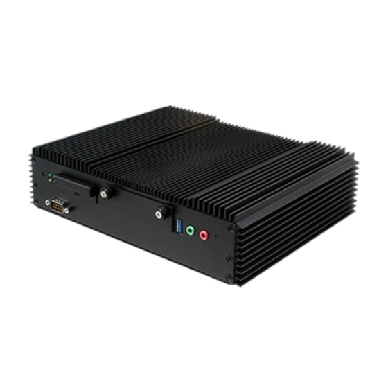
- Page 1 VMS-BYT Intel® Atom™ SoC Processor E3845 Fanless Vehicle Telematics System Quick Reference Guide Ed –07 May 2021 Copyright Notice Copyright 2021 Avalue Technology Inc., ALL RIGHTS RESERVED. Part No. E2017HA90A3R...
- Page 2 These answers are normally a lot more detailed than the ones we can give over the phone. So please consult the user’s manual first. To receive the latest version of the user’s manual; please visit our Web site at: http://www.avalue.com.tw/ 2 VMS-BYT Quick Reference Guide...
-
Page 3: Table Of Contents
System Overview ....................11 1.4.1 Front View ..........................11 1.4.2 Rear View ........................... 11 Hardware Configuration ................... 12 VMS-BYT connector mapping ................13 2.1.1 Serial Port 1 connector (COM1)....................13 2.1.2 Serial Port 2 connector/ CAN connector (COM2/CAN) ............. 14 2.1.3 DC power-in connector (DC-in).................... - Page 4 Socket 0 CPU Information ....................... 50 3.6.2.7 PPM Configuration ........................... 51 3.6.2.8 Thermal Configuration ........................51 3.6.2.9 IDE Configuration..........................52 3.6.2.10 Network Stack Configuration ......................53 3.6.2.11 CSM Configuration........................... 53 3.6.2.12 USB Configuration ........................... 54 4 VMS-BYT Quick Reference Guide...
- Page 5 Install MBI Driver ....................78 Install TXEI Driver ....................79 Install VGA Driver ....................80 Install Audio Driver (For Realtek ALC888S) ............81 Install Gigabit Driver .................... 82 Install USB3.0 Driver ................... 83 5. Command Summary ....................84 VMS-BYT Quick Reference Guide...
-
Page 6: Getting Started
Place all electronic components in a static-dissipative surface or static-shielded bag when they are not in the chassis. 1.2 Packing List 1 x VMS-BYT Intel® Atom™ SoC Processor E3845 Fanless Vehicle Telematics System Other major components include the followings: ... -
Page 7: System Specifications
VGA : 2560 x 1080 @ 60Hz Resolution LVDS : 1600 x 1200 @ 60Hz Audio AC97 Codec Realtek ALC888S HD codec Audio Interface 2 x Mic-In and 2 x Line-Out Ethernet VMS-BYT Quick Reference Guide... - Page 8 ACC Function (JACC1) sets up as Enable AT/ATX Jumper (JAT1) sets up as AT 2. Industrial PC Power Mode: BIOS sets up as Industrial PC ACC Function (JACC1) sets up as Disable AT/ATX Jumper (JAT1) sets up as AT or ATX 8 VMS-BYT Quick Reference Guide...
- Page 9 User can skip the delay time to turn off VMS-BYT if pressing power button. VMS-BYT will automatically power off, if the delay time ends up. If it still doesn’t power off and the time exceeds 60sec, VMS-BYT will be forced power off immediately.
- Page 10 14. VMS-BYT will shut down completely, and then power on again automatically, if the ignition is turned on again and the power off delay ended. 15. VMS-BYT will cancel the delay and stayed in power off status, if the ignition is turned off again and power on delay is in process.
-
Page 11: System Overview
Serial port 2 connector COM2/CAN CAN connector DC-in DC power-in connector DC-out DC power-out connector 2 x RJ-45 Ethernet connector LVDS connector LVDS 2 x USB 2.0 connector 1 x USB 3.0 connector VGA connector VMS-BYT Quick Reference Guide 11... -
Page 12: Hardware Configuration
VMS-BYT 2. Hardware Configuration Jumper and Connector Setting, Driver and BIOS Installing For advanced information, please refer to: 1- EBM-BYTV included in this manual. Note: If you need more information, please visit our website: http://www.avalue.com.tw 12 VMS-BYT Quick Reference Guide... -
Page 13: Vms-Byt Connector Mapping
In RS-232 Mode Signal PIN PIN Signal NDCD# NDSR# NRXD NRTS# NTXD NCTS# NDTR# NRI# In RS-422 Mode Signal PIN PIN Signal TxD1- TxD1+ RxD1+ RxD1- In RS-485 Mode Signal PIN PIN Signal DATA1- DATA1+ VMS-BYT Quick Reference Guide 13... -
Page 14: Serial Port 2 Connector/ Can Connector (Com2/Can)
COM2. NRXD NRTS# NTXD NCTS# CAN BUS NDTR# NRI# DB9/M 1708- In RS-422 Mode 1708+ 1939- Signal PIN PIN Signal 1939+ TxD1- TxD1+ RxD1+ RxD1- In RS-485 Mode Signal PIN PIN Signal DATA1- DATA1+ 14 VMS-BYT Quick Reference Guide... -
Page 15: Dc Power-In Connector (Dc-In)
2.1.3 DC power-in connector (DC-in) Signal VIN + (BAT+) ACC (IGN) VIN- (BAT-) 2.1.4 DC power-out connector (DC-out) Signal +12V 2.1.5 VGA connector (VGA) Signal PIN Signal PIN Signal GREEN DDCDAT BLUE HSYNC VSYNS DDCCLK VMS-BYT Quick Reference Guide 15... -
Page 16: Lvds Connector (Lvds)
VBRIGHT This connector included LVDS, USB, 12V and 5V USB_VCC interfaces. CLK+ USB_GND CLK- 2.1.7 General purpose I/O connector (GPIO) Signal Signal PIN Signal DIO_GPO0 DIO_GPI2 DIO_GPI0 DIO_GPO3 +3.3V DIO_GPO1 DIO_GPI3 DIO_GPI1 MBCLK DIO_GPO2 SMB_DATA 16 VMS-BYT Quick Reference Guide... -
Page 17: Ebm-Bytv Overviews
Quick Reference Guide 2.2 EBM-BYTV Overviews VMS-BYT Quick Reference Guide 17... -
Page 18: Ebm-Bytv Jumper & Connector List
7 x 2 header, pitch 2.00 mm CAN1 CAN Module slot CAN2 CAN box connector 9 x 1 wafer, pitch 2.00 mm MPCIE1/2 Mini PCI Express connector 1/2 52 pin PWRBTN Power button RSTBTN Reset button 18 VMS-BYT Quick Reference Guide... - Page 19 5 x 1 wafer, pitch 2.00 mm Front Panel connector 2 4 x 1 wafer, pitch 2.50 mm DCOUT_S1 DC Output connector 6 x 1 wafer, pitch 2.50 mm JEC_ROM1 EC Debug connector 5 x 2 header, pitch 2.00 mm VMS-BYT Quick Reference Guide 19...
-
Page 20: Ebm-Bytv Jumpers & Connectors Settings
VMS-BYT 2.4 EBM-BYTV Jumpers & Connectors settings 2.4.1 Clear CMOS (JCMOS1) Protect* Clear CMOS *Default 2.4.2 COM 1/2 pin 9 signal selector (JRI1/2) JRI1 Ring* JRI2 +12V * Default 20 VMS-BYT Quick Reference Guide... -
Page 21: At/Atx Jumper (Jat1)
Quick Reference Guide 2.4.3 AT/ATX Jumper (JAT1) *Default Note: This function will be active if ACC Function (JACC1) sets up Disable (Industrial PC power mode). 2.4.4 LCD backlight brightness adjustment (JVR1) PWM Mode* DC Mode * Default VMS-BYT Quick Reference Guide 21... -
Page 22: Iet Interface Dp Mode Selector (Jddi1)
It is Vehicle PC power mode (Power on/off controlled by Ignition or Power button) if ACC Function sets up as Enable. It is Industrial PC power mode (Power on/off controlled by Power button) if ACC Function sets up as Disable. 22 VMS-BYT Quick Reference Guide... -
Page 23: Digital Input Selector (Jdi1)
Quick Reference Guide 2.4.7 Digital Input selector (JDI1) Dry* Mode Digital Input Logic level 1: Close to GND Logic level 0: Open Logic level 1: < 3V Logic level 0: 5V ~ 30V * Default VMS-BYT Quick Reference Guide 23... -
Page 24: Digital Output Selector (Jdo1)
VMS-BYT 2.4.8 Digital Output selector (JDO1) Dry* * Default Note: Output Voltage: Max 250 mA per channel, current sink type. 24 VMS-BYT Quick Reference Guide... -
Page 25: Serial Port 1/ 2 - Rs485 Mode Selector (Sw1)
485RXN external OPEN* biasing resistor In Serial Port 2 mode Auto Direction RTS# Control* 485TXP external OPEN* biasing resistor 485TXN external OPEN* biasing resistor 485RXP external OPEN* biasing resistor 485RXN external OPEN* biasing resistor VMS-BYT Quick Reference Guide 25... -
Page 26: Power Input Selector (Sw2)
VMS-BYT 2.4.10 Power Input selector (SW2) +12V* +24V +9V-+36V * Default 2.4.11 CAN/COM selector (JCAN1) COM* * Default 26 VMS-BYT Quick Reference Guide... -
Page 27: Lpc Port Connector (Jlpc1)
Quick Reference Guide 2.4.12 LPC port connector (JLPC1) Signal PIN PIN Signal LPC_AD0 +3.3V LPC_AD1 LPC_PORT80_RST# LPC_AD2 LPC_FRAME# LPC_AD3 LPC1_PORT80_CLK SERIRQ +5VSB 2.4.13 LCD inverter connector (JBKL1) Signal VBRIGHT BKLEN +12V VMS-BYT Quick Reference Guide 27... -
Page 28: Spi Connector (Spi1)
VMS-BYT 2.4.14 SPI connector (SPI1) Signal PIN PIN Signal SPI_HOLD# SPI_ROM_MOSI SPI_ROM_MISO_R SPI_ROM_CLK SPI_ROM_CS# +VSPI_BIOS 2.4.15 Front Panel Connector 1 (CN1) Signal PWR_BTN_IN# SYSRST# +5VSB PWR_LED- 28 VMS-BYT Quick Reference Guide... -
Page 29: Front Panel Connector 2 (Cn6)
Quick Reference Guide 2.4.16 Front Panel Connector 2 (CN6) Signal +12V 2.4.17 DC Output connector (DCOUT_S1) Signal +VOUT_12V +VOUT_12V +VOUT_12V VMS-BYT Quick Reference Guide 29... -
Page 30: Ec Debug Connector (Jec_Rom1)
VMS-BYT 2.4.18 EC Debug connector (JEC_ROM1) Signal Signal EC_SMDAT_DE EC_SMCLK_D EBUG EC_HOLD# EC_FMOSI EC_FMISO EC_FSCK EC_FSCE# +VSPI_EC 2.4.19 On-board header for USB2.0 (JUSB1) Signal USBVCC_HEADER USB_HUB2_DN_1 USB_HUB2_DP_1 30 VMS-BYT Quick Reference Guide... -
Page 31: On-Board Header For Usb2.0 (Jusb2)
Quick Reference Guide 2.4.20 On-board header for USB2.0 (JUSB2) Signal USBVCC_BT USB_HUB2_DN_4 USB_HUB2_DP_4 BT_EN 2.4.21 Clear CMOS (Reserved) (JCMOS2) Signal ILB_RTC_RST# ILB_RTC_R_TEST# VMS-BYT Quick Reference Guide 31... -
Page 32: General Purpose I/O Connector (Dio1)
VMS-BYT 2.4.22 General purpose I/O connector (DIO1) Signal Signal +3.3V SMB_DATA SMB_CLK DIO_GPI3 DIO_GPO3 DIO_GPI2 DIO_GPO2 DIO_GPI1 DIO_GPO1 DIO_GPI0 DIO_GPO0 2.4.23 MCU download connector (JM1) Signal +MCU MCU_VPP_MCLR# ICSP-CLK ICSP-DAT 32 VMS-BYT Quick Reference Guide... -
Page 33: Can Module Slot (Can1)
Quick Reference Guide 2.4.24 CAN Module slot (CAN1) Signal Signal CAN_PWR CAN_8 CAN_IND CAN_9 BAT_GND CAN_WAKE CAN_11 SINB_CAN CAN_12 SOUTB_CAN CAN_13 CAN_14 2.4.25 CAN box connector (CAN2) Signal BAT_PWR CAN_8 CAN_9 BAT_GND CAN_11 CAN_12 CAN_13 CAN_14 VMS-BYT Quick Reference Guide 33... -
Page 34: Serial Port Connector 2 (Com2)
NRTSB# NCTSB# NRIB# 2.4.27 LVDS connector (JLVDS1) Signal PIN PIN Signal +3.3V +3.3V LVDS_DATA0_P LVDS_DATA1_P LVDS_DATA0_N LVDS_DATA1_N LVDS_DATA2_P LVDS_DATA3_P LVDS_DATA2_N LVDS_DATA3_N LVDS_DATA4_P LVDS_DATA5_P LVDS_DATA4_N LVDS_DATA5_N LVDS_DATA6_P LVDS_DATA7_P LVDS_DATA6_N LVDS_DATA7_N LVDS_CLK1_P LVDS_CLK2_P LVDS_CLK1_N LVDS_CLK2_N +12V +12V 34 VMS-BYT Quick Reference Guide... -
Page 35: Installing Pci-E Devices, Memory, Hard Disk & Cf Card
PCI-e device Installation: Insert MPCIE cards into designated locations and fasten with 4 screws to complete MPCIE installation. Step 2. Memory Installation: Slide the DDR3 SODIMM into the memory socket and press it down until properly seated. VMS-BYT Quick Reference Guide 35... - Page 36 Step 3. Secure HDD by means of 4 screws. Step 4. CF card Installation: Unlock the screw from the rear side of the System. Step 5. Put the CF card into the socket and fasten the screw back. 36 VMS-BYT Quick Reference Guide...
-
Page 37: Installing Mounting Brackets
Quick Reference Guide 2.6 Installing Mounting Brackets Step 1. Position brackets on both sides, matching the holes on the system. Step 2. Insert and fasten screw on each side of the system to secure Mounting brackets. VMS-BYT Quick Reference Guide 37... -
Page 38: Bios Setup
VMS-BYT 3.BIOS Setup 38 VMS-BYT Quick Reference Guide... -
Page 39: Introduction
If you do not press the keys at the correct time and the system does not boot, an error message will be displayed and you will again be asked to. Press F1 to Continue, DEL to enter SETUP VMS-BYT Quick Reference Guide 39... -
Page 40: Using Setup
Note: Some of the navigation keys differ from one screen to another. To Display a Sub Menu Use the arrow keys to move the cursor to the sub menu you want. Then press <Enter>. A “” pointer marks all sub menus. 40 VMS-BYT Quick Reference Guide... -
Page 41: Getting Help
BIOS Vendor and your systems manufacturer to provide the absolute maximum performance and reliability. Even a seemingly small change to the chipset setup has the potential for causing you to use the override. VMS-BYT Quick Reference Guide 41... -
Page 42: Bios Setup
Note: The BIOS setup screens shown in this chapter are for reference purposes only, and may not exactly match what you see on your screen. Visit the Avalue website (www.avalue.com.tw) to download the latest product and BIOS information. 42 VMS-BYT Quick Reference Guide... -
Page 43: Advanced Menu
Enable ACPI Auto Disabled[Default], Enables or Disables BIOS ACPI Auto Configuration Enabled Configuration. Enables or Disables System ability to Disabled Enable Hibernation Hibernate (OS/S4 Sleep State). This Enabled[Default], option may be not effective with some VMS-BYT Quick Reference Guide 43... -
Page 44: It8528 Super Io Configuration
You can use this item to set up or change the IT8528 Super IO configuration for serial ports. Please refer to 3.6.2.2.1~ 3.6.2.2.2 for more information. Item Description Serial Port 1 Configuration Set Parameters of Serial Port 1 (COMA). Serial Port 2 Configuration Set Parameters of Serial Port 2 (COMB). 44 VMS-BYT Quick Reference Guide... -
Page 45: Serial Port 1 Configuration
UART 232[Default] Change the Serial Port as UART 232 422 485 UART 485 RS232/ 422/ 485. UART 422 Disabled[Default] 422/ 485 termination TERM from GPIO. Enabled 10M bps Slew limiting SLEW from GPIO. 250k bps[Default] VMS-BYT Quick Reference Guide 45... -
Page 46: Serial Port 2 Configuration
UART 232[Default] Change the Serial Port as UART 232 422 485 UART 485 RS232/ 422/ 485 UART 422 Disabled[Default] 422/ 485 termination TERM from GPIO. Enabled 10M bps Slew limiting SLEW from GPIO. 250k bps[Default] 46 VMS-BYT Quick Reference Guide... -
Page 47: Ec 8528 H/W Monitor
20 Sec 1 Min 5 Min Power Off Delay 10 Min Power Off Delay. 30 Min 1 Hour 6 Hour 18 Hour Disabled[Default] Vin Work/ Shutdown (11.5V, 10.5V)/(23V,21V) Vin Work/ Shutdown. (12.0V, 11.0V)/(24V,22V) VMS-BYT Quick Reference Guide 47... -
Page 48: S5 Rtc Wake Settings
Enable or disable System wake on alarm Disabled[Default], event. Select Fixed Time, system will wake on Wake system from S5 Fixed Time the hr::min::sec specified. Select Dynamic Dynamic Time Time, System will wake on the current time + Increase minute(s). 48 VMS-BYT Quick Reference Guide... -
Page 49: Serial Port Console Redirection
Console Redirection Enable or Disable. Enabled 3.6.2.6 CPU Configuration Use the CPU configuration menu to view detailed CPU specification and configure the CPU. Item Options Description Active Processor Cores All[Default], Number of cores to enable in each processor VMS-BYT Quick Reference Guide 49... -
Page 50: Socket 0 Cpu Information
When enabled, a VMM can utilize the Disabled, Intel Virtualization Technology additional hardware capabilities provided by Enabled[Default] Virtualization Technology. Disabled, Power Technology Energy Efficient[Default] Enable the power management features. Custom 3.6.2.6.1 Socket 0 CPU Information 50 VMS-BYT Quick Reference Guide... -
Page 51: Ppm Configuration
3.6.2.7 PPM Configuration Item Options Description Disabled, CPU C state Report Enable/Disable CPU C state report to OS. Enabled[Default] C7[Default] This option controls Max C state that the Max CPU C-state processor will support. 3.6.2.8 Thermal Configuration VMS-BYT Quick Reference Guide 51... -
Page 52: Ide Configuration
SATA Speed Support Gen1 or Gen2. Gen2[Default] Port0 ODD SATA ODD Port Port1 ODD SATA ODD is Port0 or Port1. No ODD[Default] IDE Mode SATA Mode Select IDE/ AHCI. AHCI Mode[Default] Enabled[Default] Serial-ATA Port 0/1 Enable/Disable Serial ATA Port0/1. Disabled, 52 VMS-BYT Quick Reference Guide... -
Page 53: Network Stack Configuration
Quick Reference Guide 3.6.2.10 Network Stack Configuration Item Options Description Enabled Network Stack Enable/Disable UEFI Network Stack. Disabled[Default], 3.6.2.11 CSM Configuration Item Options Description Enabled[Default] CSM Support Enable/Disable CSM Support. Disabled, VMS-BYT Quick Reference Guide 53... -
Page 54: Usb Configuration
Legacy only[Default] Determines OpROM execution policy for UEFI only Other PCI devices devices other than Network, Storage, or Legacy only[Default], Video. 3.6.2.12 USB Configuration The USB Configuration menu helps read USB information and configures USB settings. 54 VMS-BYT Quick Reference Guide... -
Page 55: Security Configuration
Host Controller. Auto[Default] ‘Auto’ uses default value: for a Root port it is Device power-up delay Manual 100ms, for a Hub port the delay is taken form Hub descriptor. 3.6.2.13 Security Configuration VMS-BYT Quick Reference Guide 55... -
Page 56: Intel(R) Pro/1000 6.0.24 Pci-E
TXE OVERWRITE. NORMAL: Over Write Pin OVER WRITE TXE OVERWRITE as high. (TXE enabled) OVERWRITE: Over NORMAL[Default] Write Pin as low. (TXE disabled) 3.6.2.14 Intel(R) PRO/1000 6.0.24 PCI-E Item Description Intel® PRO/1000 6.0.24 PCI-E Provides Health Status for the Drivers/Controllers. 56 VMS-BYT Quick Reference Guide... -
Page 57: Chipset
Quick Reference Guide 3.6.3 Chipset 3.6.3.1 North Bridge Item Options Description Dynamic 2 GB 2.25 GB Max TOLUD Maximum Value of TOLUD. 2.5 GB 2.75 GB 3 GB[Default] VMS-BYT Quick Reference Guide 57... -
Page 58: Intel Igd Configuration
(Fixed) Graphics Memory size used 384M/416M/448M/480M/512M by the Internal Graphics Device. 128MB Select DVMT 5.0 Total Graphics DVMT Total Gfx Mem 256MB[Default] Memory size used by the Internal Graphics Device. 128MB Aperture Size Select the Aperture Size. 256MB[Default] 58 VMS-BYT Quick Reference Guide... -
Page 59: Igd - Lcd Control
1024x768 18/1 1366x768 18/1 1024x600 18/1 1280x800 18/1 1920x1200 24/2 Port1-EDP to LVDS (Chrotel 7511) Panel CH7511 EDID Panel Option 640x480 18/1 EDID Option. 800x480 18/1 1920x1080 18/2 1280x1024 24/2 1440x900 18/2 1600x1200 24/2 1366x768 24/1 VMS-BYT Quick Reference Guide 59... -
Page 60: South Bridge
VMS-BYT 1920x1080 24/2 1680x1050 24/2 LVDS Back Light PWM Select LVDS back light PWM duty. 100%[Default] 3.6.3.2 South Bridge Item Option Description Disabled Enable or Disable the High Precision High Precision Timer Enabled[Default] Event Timer. 60 VMS-BYT Quick Reference Guide... -
Page 61: Azalia Hd Audio
Enabled = Azalia will be Disabled unconditionally Enabled. Auto = Azalia will be enabled if present disabled otherwise. Enabled[Default], HDMI Port B Enable/Disable HDMI Port B. Disabled 4 Port[Default], EBM-BYTV VerbTable EBM-BYTV VerbTable. 5 Port VMS-BYT Quick Reference Guide 61... -
Page 62: Usb Configuration
OS Selection Android Windows 7 Please change the item of OS selection to Windows 8.X if you intend to install Windows 8 OS. Enabled[Default], Disabled XHCI Mode Mode of operation of xHCI controller. Auto Smart Auto 62 VMS-BYT Quick Reference Guide... -
Page 63: Pci Express Configuration
Gen 2 Configure PCIe Port Speed. Gen 1[Default] Enabled[Default], Enable or Disable the PCI Express Port 3 in PCI Express Port 3 Disabled the Chipset. Auto[Default] Speed Gen 2 Configure PCIe Port Speed. Gen 1 VMS-BYT Quick Reference Guide 63... -
Page 64: Security
VMS-BYT 3.6.4 Security Administrator Password Set setup Administrator Password User Password Set User Password 3.6.4.1 Secure Boot menu 64 VMS-BYT Quick Reference Guide... -
Page 65: Key Management
User mode with enrolled Platform Enabled Key(PK) 2.CSM function is disabled. Secure Boot mode selector. ‘Custom’ Mode Standard Secure Boot Mode enables users to change Image Execution Custom[Default] policy and manage Secure Boot Keys. 3.6.4.1.1 Key Management VMS-BYT Quick Reference Guide 65... - Page 66 VMS-BYT 66 VMS-BYT Quick Reference Guide...
- Page 67 Quick Reference Guide VMS-BYT Quick Reference Guide 67...
- Page 68 VMS-BYT 68 VMS-BYT Quick Reference Guide...
- Page 69 Quick Reference Guide VMS-BYT Quick Reference Guide 69...
- Page 70 VMS-BYT 70 VMS-BYT Quick Reference Guide...
- Page 71 Quick Reference Guide VMS-BYT Quick Reference Guide 71...
- Page 72 VMS-BYT 72 VMS-BYT Quick Reference Guide...
- Page 73 Quick Reference Guide VMS-BYT Quick Reference Guide 73...
-
Page 74: Boot
Number of seconds to wait for setup activation Setup Prompt Timeout 1~ 65535 key. 65535(0xFFFF) means indefinite waiting. On[Default] Bootup NumLock State Select the Keyboard NumLock state Quiet Boot Disabled[Default] Enables or disables Quiet Boot option 74 VMS-BYT Quick Reference Guide... -
Page 75: Save And Exit
This option restores all BIOS settings to the factory default. This option is useful if the controller exhibits unpredictable behavior due to an incorrect or inappropriate BIOS setting. 3.6.6.4 Launch EFI Shell from filesystem device Attempts to Launch EFI Shell application (Shellx64.efi) from one of the available filesystem devices. VMS-BYT Quick Reference Guide 75... -
Page 76: Drivers Installation
VMS-BYT 4. Drivers Installation Note: Installation procedures and screen shots in this section are for your reference and may not be exactly the same as shown on your screen. 76 VMS-BYT Quick Reference Guide... -
Page 77: Install Chipset Driver
Note: The installation procedures and screen shots in this section are based on Windows 10 operation system. Step 3. Click Install. Step1. Click Next. Step 4. Click Finish to complete setup. Step 2. Click Accept. VMS-BYT Quick Reference Guide 77... -
Page 78: Install Mbi Driver
Windows 10 operation system. Step 3. Click Next to proceed setup. Step 4. Click Finish to complete setup. Step1. Click Next to start installation. Step 2. Click Yes to accept license agreement. 78 VMS-BYT Quick Reference Guide... -
Page 79: Install Txei Driver
Windows 10 operation system. Step 3. Click Next to continue installation. Step 4. Click Finish to complete setup. Step1. Click Next to start installation. Step 2. Click Next. VMS-BYT Quick Reference Guide 79... -
Page 80: Install Vga Driver
Windows 10 operation system. Step 3. Click Next. Step 4. Click Next. Step 1. Click Next to continue installation. Step 2. Step 5. Click Finish to complete setup. Click Yes to accept license agreement. 80 VMS-BYT Quick Reference Guide... -
Page 81: Install Audio Driver (For Realtek Alc888S)
All drivers can be found on the Avalue Official Website: http://www.avalue.com.tw. Note: The installation procedures and screen shots in this section are based on Windows 10 operation system. Step 1. Click Next to continue setup. Step 2. Click Finish to complete the setup. VMS-BYT Quick Reference Guide 81... -
Page 82: Install Gigabit Driver
Windows 10 operation system. Step 3. Click Next. Step 4. Click Install to proceed. Step 1. Click Next. Step 2. Click Next to accept license Step 5. Click Finish to complete the setup agreement. 82 VMS-BYT Quick Reference Guide... -
Page 83: Install Usb3.0 Driver
Windows 10 operation system. Step 3. Click Next. Step 4. Click Next to proceed. Step 1. Click Next. Step 2. Click Yes to accept license Step 5. Click Finish to complete the setup agreement. VMS-BYT Quick Reference Guide 83... -
Page 84: Command Summary
VMS-BYT Command Summary Note: Please contact our AE if you have further questions. 84 VMS-BYT Quick Reference Guide... - Page 85 ATRJ: Request J1939 FMS High Resolution Total Vehicle Distance (#33~#36) ATRH: Request Hino Truck Total vehicle distance (#33~#36) ATS(HEX:41 54 53 0D): Continue auto-send data every ATSS: Auto- send Simple Data every 100~200 ms. ATSP: Auto-send Packaging Messages every 100~200 ms. VMS-BYT Quick Reference Guide 85...
- Page 86 Packing1 Packing2 Packing 3 Packing4 Packing5 Packing1 AT#xy: The command will print designated data by ASCII code. ―xy‖ is data address, it is decimal. J1708: 00~83 J1939: 00~105. EX: AT#01, to get speed high byte. 86 VMS-BYT Quick Reference Guide...
- Page 87 FU, Average Fuel Economy (km/L) =Fu /10 Byte 24 Check sum (add numbers)= Byte1+ Byte3+Byte5+ Byte7+ Byte 25 Byte9+Byte11+ Byte13+ Byte15+Byte17+ Byte19+ Byte21+Byte23 Byte 26 Carry return ( 0x0D ) Byte 27 Line feed ( 0x0A) VMS-BYT Quick Reference Guide 87...
- Page 88 Speed=120 km/hr (78 =120 Rpm=0x0E70= 3696 (0E70 =3696 status: Bit 7: 0: Normal 1: Emergency Braking (Acceleration < -6 m/ s Bit 6: 0: Brake OFF 1: Brake ON 1: Brake Bit 5: 0: Clutch OFF 88 VMS-BYT Quick Reference Guide...
- Page 89 0: Clutch (ON/OFF) unavailable 1: Clutch (ON/OFF) available Bit 1: 0: Cruise Control (ON/OFF) unavailable 1: Cruise Control (ON/OFF) available Bit 0: 0: NORMAL 1: DTC ON 2.) Distance = D1*256+D2 (KM) 3.) Average Fuel Economy = Fu/10 VMS-BYT Quick Reference Guide 89...
- Page 90 Source Address Byte 5 Data1 Byte 6 Data2 Byte 7 Data3 Byte 8 Data4 Byte 9 Data5 Byte 10 Data6 Byte 11 Data7 Byte 12 Data8 Byte 13 Check sum Byte 14 0x0D Byte 15 0x0A 90 VMS-BYT Quick Reference Guide...
- Page 91 PIDs 128-191 describe data parameters that consist of two bytes. PIDs 192-253 The first byte following these PIDs will contain the number of data parameter bytes. 0x40 0x80 0x15 0x01 0x32 0xC8 0x0D 0x0A MID=128 PID=21 (Engine ECU temperature) Data=50 VMS-BYT Quick Reference Guide 91...
- Page 92 Byte 21 & 22 were ignored. 2.) Packing 6, Byte18~Byte19 not defined (set to ‖0‖) 3.) This is the common J1939 measurement overview showing which measurements are available. Note that not all measurements are supported by the individual engines. 92 VMS-BYT Quick Reference Guide...
- Page 93 12 15 23 0D 20 0D 00 00 00 00 00 00 00 00 00 00 1C 0D 0A Trouble code : 0494, 1512, 0D23, 0D20 (HEX) 2.) Packing 7, Byte12~Byte19 not defined (set to ‖0‖) VMS-BYT Quick Reference Guide 93...
- Page 94 Engine Total Fuel used 0,5 L / Bit gain , ETF4 Engine Total Fuel used =((ETF4*256*256*256)+(ETF3*256*256)+(ETF2*256)+ETF1)*0.5 Fuel Level (FL) , 0 to 100 %, 0.4 %/bit Fuel Level=FL*0.4 RPM Low byte, RL RPM High byte, RH RPM= (RH*256+ RL)* 0.125 94 VMS-BYT Quick Reference Guide...
- Page 95 Axle weight 0.5 kg / Bit gain (Low Byte),AWL Axle weight 0.5 kg / Bit gain (High Byte), AWH Weight=(AWH*256+AWL)*0.5 Engine total hours of Operation, EH1 Engine total hours of Operation, EH2 Engine total hours of Operation, EH3 VMS-BYT Quick Reference Guide 95...
- Page 96 #30: “b”, #31:”c” , #32:”d” #33~ High Resolution Total Vehicle Distance, 5 m/bit, 0 to 21,055,406 km =((D4*256*256*256)+(D3*256*256)+(D2*256)+D1)*0.005 (KM) #37~ The distance which can be traveled by the vehicle before the next service inspection is required SERV=(V2*256+V1)*5-160635 (KM) 96 VMS-BYT Quick Reference Guide...
- Page 97 0010 = 4.5 h reached 0011 = 15 min bef. 9 h 0100 = 9 h reached 0101 = 15 min bef. 16 h 0110 = 16h reached 1110 = Error 1111 = not available VMS-BYT Quick Reference Guide 97...
- Page 98 01 = handling information System event (B1,B0) 00 = no tachogr. Event 01 = tachogr. Event #43~ Tachogr. vehicle speed 1/256 km/h Bit gain Speed= ((VS2*256)+VS1)/256 Engine Coolant Temperature(ECT) , -40 to 210 deg C ECT=data-40 ℃ 98 VMS-BYT Quick Reference Guide...
- Page 99 00 = request is not supported 01= request is supported 10 = reserved 11 = don´t care Bit4~Bit7:Resvered #55~ Ambient Air Temperature: Temperature of air surrounding vehicle. AAT=(AATH* 256+AATL)*0.03125 -273 (deg C) #55: AATL #56: AATH VMS-BYT Quick Reference Guide 99...
- Page 100 01 = Open 01 = Locked 10 = Error 01 = Enabled 10 = Error 10 = Error 11 = Not 10 = Error 11 = Not 11 = Not available 11 = Not available available available 100 VMS-BYT Quick Reference Guide...
- Page 101 01 = Locked 10 = Error 01 = Enabled 01 = Open 10 = Error 11 = Not 10 = Error 10 = Error 11 = Not available 11 = Not 11 = Not available available available VMS-BYT Quick Reference Guide 101...
- Page 102 01 = Locked 10 = Error 01 = Enabled 01 = Open 10 = Error 11 = Not 10 = Error 10 = Error 11 = Not available 11 = Not 11 = Not available available available 102 VMS-BYT Quick Reference Guide...
- Page 103 10 = error 10 = error 11 = not 11 = not 11 = not 11 = not available available available available Selected Gear = data -125negative gear are reverse gears 00000000 = neutral 11111011 = park VMS-BYT Quick Reference Guide 103...
- Page 104 The driver ID is only available if a digital tachograph is present #91~ Engine Fuel Rate (EFR). Amount of fuel consumed by engine per liter of hour. EFR=(EFR2*256+EFR1)* 0.05 , L/h Data Range: 0 to 3,212.75 L/h EFR1 EFR2 104 VMS-BYT Quick Reference Guide...
- Page 105 1011 = Cond. Info 1100–1110 = Reserved 1111 = not available Bit 7,6,5,4: Telltale Status 3 1000 = off 1001 = Cond. Red 1010 = Cond. Yellow 1011 = Cond. Info 1100–1110 = Reserved 1111 = not available VMS-BYT Quick Reference Guide 105...
- Page 106 1011 = Cond. Info 1100–1110 = Reserved 1111 = not available Bit 7,6,5,4: Telltale Status 7 1000 = off 1001 = Cond. Red 1010 = Cond. Yellow 1011 = Cond. Info 1100–1110 = Reserved 1111 = not available 106 VMS-BYT Quick Reference Guide...
- Page 107 1011 = Cond. Info 1100–1110 = Reserved 1111 = not available Bit 7,6,5,4: Telltale Status 11 1000 = off 1001 = Cond. Red 1010 = Cond. Yellow 1011 = Cond. Info 1100–1110 = Reserved 1111 = not available VMS-BYT Quick Reference Guide 107...
- Page 108 1010 = Cond. Yellow 1011 = Cond. Info 1100–1110 = Reserved 1111 = not available #103 Battery Voltage (BV), = (data+100)/10 (V) #104 Engine Oil Filter Differential Pressure EODP= data*0.5 ( kPa) #105 YUTONG Bus, speed: 0~255 km/h 108 VMS-BYT Quick Reference Guide...
- Page 109 2.) This is the common J1708 measurement overview showing which measurements are available. Note that not all measurements are supported by the individual engines. Packing 4 & 5 will display only there is trouble code occurrence. VMS-BYT Quick Reference Guide 109...
- Page 110 — SID or PID of a standard diagnostic code. C — Diagnostic code character. Bits 4-1: Failure mode identifier (FMI) #00~ Road Speed—Indicated vehicle velocity Maximum Range: 0.0 to 205.2 km/h (0.0 to 127.5 mph) speed=(SHB*256+SLB)/256 Speed Low Byte (SLB) 110 VMS-BYT Quick Reference Guide...
- Page 111 Engine Total Fuel used 0,5 L / Bit gain , ETF3 Engine Total Fuel used 0,473 L / Bit gain , ETF4 Fuel Level—Ratio of volume of fuel to the total volume of the primary fuel VMS-BYT Quick Reference Guide 111...
- Page 112 Engine total hours of Operation, EH3 Engine total hours of Operation, EH4 #20~ Vehicle Identification Number—Vehicle Identification Number (VIN) as assigned by the vehicle manufacturer. Vehicle identification number, aabbccddeeffgghh “ATI” command can show max 20 character VIN 112 VMS-BYT Quick Reference Guide...
- Page 113 If vehicle does not provide TVD, AT1708 replace the information with the calculated distance, deviation is 0.5%, The first time connection AT1708 please command ATR to clear distance memory. #37~ Fuel Rate (Instantaneous)—Amount of fuel consumed by engine per unit VMS-BYT Quick Reference Guide 113...
- Page 114 Bits 5-4: ABS retarder control Bits 3-2: ABS brake control Bits 1-0: ABS warning lamp 00 Off/Not active 01 On/Active 10 Error condition 11 Not available Parking Brake Switch Status—Identifies the state (active/inactive) of the parking brake switch Bit 7: 1=active/0=inactive 114 VMS-BYT Quick Reference Guide...
- Page 115 DTC #1 #54: a #55: b #56: c DTC #2 #57: a #58: b #59: c DTC #3 #60: a #61: b #62: c DTC #4 #63: a #64: b #65: c DTC #5 #66: a #67: b VMS-BYT Quick Reference Guide 115...
- Page 116 2.) Trouble code: 40 37 80 8 CA 80 A AA 80 B AA 80 C AA 80 1 AA FC D A Trouble code: MID 128 (H80) PID 8(H8) Diagnostic code character (CA), FMI= A, bit4~bit1 116 VMS-BYT Quick Reference Guide...
- Page 117 1993 (P), 1994 (R), 1995 (S), 1996 (T), 199 7(V), Model Year 1998 (W), 1999 (X), 2000 (Y),2001(1), 2002 (2), 2003 (3)….. Production Plant Sequential The sequence of the vehicle for production as it 178227 Number rolled of the manufacturers assembly line. VMS-BYT Quick Reference Guide 117...
Need help?
Do you have a question about the VMS-BYT and is the answer not in the manual?
Questions and answers