
Related Manuals for Avalue Technology SLP-ZXE


Summary of Contents for Avalue Technology SLP-ZXE
- Page 1 SLP-ZXE Zhaoxin KX-6000 series BGA processor Expandable Slot PC Quick Reference Guide Ed –29 March 2024 Copyright Notice Copyright 2024 Avalue Technology Inc., ALL RIGHTS RESERVED. Part No. E2017SLZEA0R...
- Page 2 SLP-ZXE Document Amendment History Revision Date Comment March 2024 Avalue Initial Release 2 SLP-ZXE Quick Reference Guide...
- Page 3 For detailed information, please always refer to the electronic user's manual. Copyright Notice © 2024 by Avalue Technology Inc. All rights are reserved. No parts of this manual may be copied, modified, or reproduced in any form or by any means for commercial use without the prior written permission of Avalue Technology Inc.
- Page 4 ㆍDescription of your software (operating system, version, application software, etc.) ㆍA complete description of the problem ㆍThe exact wording of any error messages To receive the latest version of the user’s manual; please visit our Web site at: www.avalue.com 4 SLP-ZXE Quick Reference Guide...
-
Page 5: Purpose
On the other hand, if the new product defect is resulting from incorrect configuration or erroneous use by the user instead of any problem of the hardware itself, the customer will also be requested to pay for relevant handling fees. SLP-ZXE Quick Reference Guide... -
Page 6: Ruling Of An Out-Of-Warranty Defect
Lacking detailed statement of fault steps also makes the problem hard to be identified, sometimes resulting in second-time repairs. 6 SLP-ZXE Quick Reference Guide... -
Page 7: Return Of Faulty Product For Repair
Product has been altered or its label of the serial number has been torn off. Product functionality issues resulting from improper use by the user, unauthorized dismantle or alteration, unfit operation environment, improper maintenance, accident SLP-ZXE Quick Reference Guide... -
Page 8: Maintenance Service Of Phased-Out Products
If the customer demands an additional maintenance analysis report, a service fee of various level will be charged depending on the warranty status. In case the analysis result shows that the defect attributes to Avalue’s faulty design or process, the analysis fee will be exempted. 8 SLP-ZXE Quick Reference Guide... -
Page 9: Service Products
9. Position the power cord so that people cannot step on it. Do not place anything over the power cord. 10. All cautions and warnings on the equipment should be noted. 11. If the equipment is not used for a long time, disconnect it from the power source to SLP-ZXE Quick Reference Guide... - Page 10 The equipment has obvious signs of breakage. 14. CAUTION: Danger of explosion if battery is incorrectly replaced. Replace only with the same or equivalent type recommended by the manufacturer. 15. Equipment intended only for use in a RESTRICTED ACCESS AREA. 10 SLP-ZXE Quick Reference Guide...
- Page 11 A NOTE provides additional information intended to avoid Note inconveniences during operation. Direct current. Alternating current Stand-by, Power on FCC Certification CE Certification Follow the national requirements for disposal of equipment. Stacking layer limit This side up SLP-ZXE Quick Reference Guide 11...
- Page 12 SLP-ZXE Fragile Packaging Beware of water damage, moisture-proof Carton recyclable Handle with care Follow operating instructions of consult instructions for use. 12 SLP-ZXE Quick Reference Guide...
- Page 13 EXPLOSION ou une fuite de liquide ou de gaz inflammable. - UNE BATTERIE soumise à une pression d'air extrêmement basse pouvant entraî ner une EXPLOSION ou une fuite de liquide ou de gaz inflammable. SLP-ZXE Quick Reference Guide 13...
-
Page 14: Table Of Contents
SLP-ZXE Rear View ......................23 1.5 System Dimensions ....................24 1.6 Operating Principle ....................25 Hardware Configuration ..................26 2.1 SLP-ZXE connector mapping .................. 27 2.1.1 Serial Port 1~4 connector (COM1~4) ..................27 2.2 Powering On the System ..................27 The power of this system can be less than 250w 20A. - Page 15 3.2 Install Audio Driver ....................50 3.3 Install LAN Driver ....................51 3.4 Install LAN Driver ....................52 3.5 Install Fintek Serial Patch Driver ................54 4.BIOS Setup ........................55 4.1 Introduction ......................56 4.2 Starting Setup ......................56 SLP-ZXE Quick Reference Guide 15...
- Page 16 PCIE Configuration ....................... 74 4.6.3.2 South Bridge .......................... 75 4.6.3.2.1 USB Configuration ......................75 4.6.3.2.2 SATA Configuration ...................... 76 4.6.3.2.3 HDAC Configuration ..................... 76 4.6.3.3 Board & Panel Configuration ....................77 4.6.4 Security ..........................78 16 SLP-ZXE Quick Reference Guide...
- Page 17 4.6.6.2 Discard Changes and Reset ....................81 4.6.6.3 Restore Defaults ........................81 4.6.6.4 Launch EFI Shell from filesystem device ................81 5. Maintenance & Troubleshooting................. 82 6. Product Application ..................... 88 7. Operating the Device ....................89 SLP-ZXE Quick Reference Guide 17...
-
Page 18: Getting Started
1.2 Packing List Before installation, please ensure all the items listed in the following table are included in the package. Item Description Q’ty SLP-ZXE Zhaoxin KX-6000 series BGA processor Expandable Slot PC Wallmount kit(screws & wallmount bracket) 18 SLP-ZXE Quick Reference Guide... - Page 19 Step 3: Carefully cut the tape sealing the box. Only cut deep enough to break the tape. Step 4: Open the inside box. Step 5: Lift the panel PC out of the boxes. Step 6: Remove the peripheral parts box from the main box. SLP-ZXE Quick Reference Guide 19...
-
Page 20: System Specifications
HDMI 2 x HDMI 1.4b RJ-45 3 x RJ-45 Power Button 1 x Push Button for Power on/off Wire-Control 2-Pin Terminal Block Power On/Off 1 x Power LED(Blue) LED Indicator 1 x Storage LED (Red) 20 SLP-ZXE Quick Reference Guide... - Page 21 -40°C ~ 75°C (-40 ~ 167°F) Operating 40°C @ 95% Relative Humidity, Non-condensing Humidity Dimension 182 x 221.8 x 220 mm (W*L*H) Weight 5.35KG Reliability Random Vibration Operation: Vibration Test 1. PSD: 0.03622G²/Hz, 1.5 Grms 2. operation mode SLP-ZXE Quick Reference Guide 21...
- Page 22 Package drop test. Drop Test 1 One corner, three edges, six faces 2 ISTA 2A, IEC-60068-2-32 Test: Ed Mounting Kit Din Rail, Wallmount Software Support Win10, 中标麒麟 OS Information Note: Specifications are subject to change without notice. 22 SLP-ZXE Quick Reference Guide...
-
Page 23: System Overview
Serial Port 3-6 connector PS/2 keyboard & mouse KB&MS 4 x 2 header, pitch 2.00mm header PWR1 Power connector 2 x 2 wafer, pitch 4.20mm PWR1 DC Input connector 3 x 1 wafer, pitch 5.08mm Power Button connector SLP-ZXE Quick Reference Guide 23... -
Page 24: System Dimensions
SLP-ZXE 1.5 System Dimensions (Unit: mm) 24 SLP-ZXE Quick Reference Guide... -
Page 25: Operating Principle
- Turn ON the system. - Press the power ON/OFF icon firmly to turn power ON/OFF. - The power ON/OFF LED will turn blue to indicate power is on. - Check with the Icon behavior for power status. SLP-ZXE Quick Reference Guide 25... -
Page 26: Hardware Configuration
SLP-ZXE 2. Hardware Configuration For advanced information, please refer to: 1- EMX-ZXEDP included in this manual. Note: If you need more information, please visit our website: www.avalue.com 26 SLP-ZXE Quick Reference Guide... -
Page 27: Slp-Zxe Connector Mapping
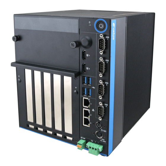
ACC On signal. Power 2 connector is a 4-pin terminal that can directly connect to a power adapter. The supported power input voltages are: Power 1 (DIN connector)): 12 V ~ 28 V Power 2 (terminal block)): 12 V ~ 28 V SLP-ZXE Quick Reference Guide 27... - Page 28 SLP-ZXE Power Input Connector Power Button 28 SLP-ZXE Quick Reference Guide...
-
Page 29: Emx-Zxedp Overviews
Quick Reference Guide 2.4 EMX-ZXEDP Overviews SLP-ZXE Quick Reference Guide 29... -
Page 30: Emx-Zxedp Jumper & Connector List
3 x 2 header, pitch 2.00 mm JRS485_1/2 connector 1/2 5 x 2 header, pitch 2.00mm JLPC1 LPC connector 5 x 1 header, pitch 2.00mm JSMB1 SMBus connector JVGA1 VGA connector 3 x 2 header, pitch 2.00 mm 30 SLP-ZXE Quick Reference Guide... - Page 31 Quick Reference Guide USB3/4 USB connector 3/4 SODIMM1/2 206-pin DDR4 SO-DIMM socket LAN1/2-3 RJ-45 Ethernet 1/2-3 DCIN1 DC Power-in connector HDMI connector 1/2 HDMI1/2 HEATSINK1 ZX-200 heatsink Gold Finger SIM1 SIM card slot SLP-ZXE Quick Reference Guide 31...
-
Page 32: Setting Jumpers & Connectors
SLP-ZXE 2.6 Setting Jumpers & Connectors 2.6.1 Serial port 1 pin9 signal select (JRI1) Ring* +12V * Default 2.6.2 Serial port 1 pin9 signal select (JRI2) Ring* +12V * Default 32 SLP-ZXE Quick Reference Guide... -
Page 33: Clear Cmos (Jcmos1)
Quick Reference Guide 2.6.3 Clear CMOS (JCMOS1) Protect* Clear CMOS * Default 2.6.4 AT/ATX Power Mode Select (JSATX1) ATX* * Default SLP-ZXE Quick Reference Guide 33... -
Page 34: Lvds Back Light Power Selection (Jsbkl1)
SLP-ZXE 2.6.5 LVDS Back Light power selection (JSBKL1) PWM Mode* DC Mode * Default 2.6.6 General purpose I/O connector (DIO1) Signal PIN PIN Signal SMB_DATA_VCC 18 17 SMB_CLK_VCC 34 SLP-ZXE Quick Reference Guide... -
Page 35: Power Connector (Pwr1)
Quick Reference Guide 2.6.7 Power connector (PWR1) Signal PIN PIN Signal +VDC12_26V +VDC12_26V 2.6.8 SATA Power connector (SPWR1) Signal +V5S_SATA1 +V12S_SATA1 SLP-ZXE Quick Reference Guide 35... -
Page 36: Usb Connector (Usb1)
SLP-ZXE 2.6.9 USB connector (USB1) Signal PIN PIN Signal +V5A__HUB1-4 +V5A__HUB1-4 USB_PN0__R USB_PN1__R USB_PP0__R USB_PP1_R 2.6.10 USB connector (USB2) Signal USB_PP2_R USB_PN2__R +V5A__HUB1-4 36 SLP-ZXE Quick Reference Guide... -
Page 37: Lpc Connector (Jlpc1)
Quick Reference Guide 2.6.11 LPC connector (JLPC1) Signal PIN PIN Signal LPC_AD0 +3.3V LPC_AD1 PCIRST# LPC_AD2 LPC_LFRAME# LPC_AD3 CLK_33M_LPC LPC_SERIRQ 2.6.12 Miscellaneous setting connector (JSPI1) Signal PIN PIN Signal + V3.3A_SPI SPI_CS0# SPI_CLK SPI_MISO SPI_MOSI SPI_HOLD# SPI_WP# SLP-ZXE Quick Reference Guide 37... -
Page 38: Speaker Connector (Spk1)
SLP-ZXE 2.6.13 Speaker connector (SPK1) Signal LSPK+ LSPK- RSPK+ RSPK- 2.6.14 Front Panel connector (FPT1) Signal PIN PIN Signal FP_PWR_BTN_EC# EXT_SYSRST# PWR_LED- HDD_LED- PWR_LED+ HDD_LED+ 38 SLP-ZXE Quick Reference Guide... -
Page 39: Front Panel Connector (Fpt2)
Quick Reference Guide 2.6.15 Front Panel connector (FPT2) Signal PIN PIN Signal SPKR- BLK_BRI_DN# BLK_BRI_UP# BLK_VR_MOD SPKR+ 2.6.16 System fan connector 1 (JFAN1) Signal +V12S_FAN1 CPUFANIN FAN_PWM0 SLP-ZXE Quick Reference Guide 39... -
Page 40: System Fan Connector 2 (Jfan2)
SLP-ZXE 2.6.17 System fan connector 2 (JFAN2) Signal +V12S_FAN2 SYSFANIN FAN_PWM1 2.6.18 Serial port connector (COM1) Signal PIN PIN Signal COM_RI#_1 COM_CTS#_1 COM_RTS#_1 COM_DSR#_1 COM_DTR#_1 COM_TXD_1 COM_RXD_1 COM_DCD#_1 40 SLP-ZXE Quick Reference Guide... -
Page 41: Serial Port Connector (Com2)
Quick Reference Guide 2.6.19 Serial port connector (COM2) Signal PIN PIN Signal COM_RI#_2 COM_CTS#_2 COM_RTS#_2 COM_DSR#_2 COM_DTR#_2 COM_TXD_2 COM_RXD_2 COM_DCD#_2 2.6.20 Serial Port2 RS485/422 Mode connector (JRS485_1) Signal PIN PIN Signal 485_422TX1- 422RX1- 485_422TX1+ 422RX1+ SLP-ZXE Quick Reference Guide 41... -
Page 42: Serial Port2 Rs485/422 Mode Connector (Jrs485_2)
SLP-ZXE 2.6.21 Serial Port2 RS485/422 Mode connector (JRS485_2) Signal PIN PIN Signal 485_422TX2- 422RX2- 485_422TX2+ 422RX2+ 2.6.22 Front Audio connector (FAUD1) Signal PIN PIN Signal LINEOUT1 _JD LINEOUT_L MIC1_JD LINEOUT_R ACZ_DET# MIC1_RIN MIC1_LIN 42 SLP-ZXE Quick Reference Guide... -
Page 43: Smbus Connector (Jsmb1)
Quick Reference Guide 2.6.23 SMBus connector (JSMB1) Signal +SMB_3.3V SMBALRT#_S SMB_CLK_S SMB_DATA_S 2.6.24 PS/2 keyboard & mouse header (KBMS1) Signal PIN PIN Signal MSCLK MSDAT +V5A_KBMS KBCLK KBDAT SLP-ZXE Quick Reference Guide 43... -
Page 44: Lcd Inverter Connector (Jbkl1)
SLP-ZXE 2.6.25 LCD Inverter connector (JBKL1) Signal LVDS_BKLTCTL LVDS_BKLT_EN +V12S_INV 2.6.26 EC Debug (JEC_DEBUG1) Signal EC_SMCLK EC_SMDAT 44 SLP-ZXE Quick Reference Guide... -
Page 45: Edp-Panel Connector (Edp 1)
Signal EDP_PanelTXN0 EDP_PanelTXN3 EDP_PanelTXP0 EDP_PanelTXP3 EDP_PanelTXN1 EDP_PanelTXP1 11 12 EDP_PanelAUXN 14 EDP_PanelAUXP EDP_PanelTXN2 15 EDP_PanelTXP2 17 EDP_Panel_HPD EDP_VCC_PAL EDP_VCC_PAL 2.6.28 JVGA1 connector (JVGA1) Signal PIN PIN Signal CRT_Z_RED +V5S_VGA CRT_Z_GREEN CRT_Z_BLUE CRT_Z_DDC_CLK CRT_Z_DDC_DATA CRT_Z_VSYNC CRT_Z_HSYNC SLP-ZXE Quick Reference Guide 45... -
Page 46: Lvds Connector (Lvds1)
10 LVDS_DATA0_P LVDS_DATA1_N 11 12 LVDS_DATA0_N LVDS_DATA3_P 15 16 LVDS_DATA2_P LVDS_DATA3_N 17 18 LVDS_DATA2_N LVDS_DATA5_P 21 22 LVDS_DATA4_P LVDS_DATA5_N 23 24 LVDS_DATA4_N LVDS_DATA7_P 27 28 LVDS_DATA6_P LVDS_DATA7_N 29 30 LVDS_DATA6_N LVDS_CLK2_P LVDS_CLK1_P LVDS_CLK2_N LVDS_CLK1_N +V12S_LVDS +V12S_LVDS 46 SLP-ZXE Quick Reference Guide... -
Page 47: Serial Port3-6 Connector (Com3-6)
PIN PIN Signal COM_DCD_3 COM_RXD_3 COM_TXD_3 COM_DTR#_3 COM_DSR#_3 COM_RTS#_3 COM_CTS#_3 COM_RI#_3 COM_DCD_4 COM_RXD_4 COM_TXD_4 COM_DTR#_4 COM_DSR#_4 COM_RTS#_4 COM_CTS#_4 COM_RI#_4 COM_DCD_5 COM_RXD_5 COM_TXD_5 COM_DTR#_5 COM_DSR#_5 COM_RTS#_5 COM_CTS#_5 COM_RI#_5 COM_DCD_6 COM_RXD_6 COM_TXD_6 COM_DTR#_6 COM_DSR#_6 COM_RTS#_6 COM_CTS#_6 COM_RI#_6 SLP-ZXE Quick Reference Guide 47... -
Page 48: Drivers Installation
HID touch digitizer built-in driver in Windows 10 or later. Note: Installation procedures and screen shots in this section are for your reference and may not be exactly the same as shown on your screen. 48 SLP-ZXE Quick Reference Guide... -
Page 49: Install Vga Driver
Windows 10 operation system. If the warning message appears while the installation process, click Continue to go on. Step 1. Click Next to continue installation. Step 2. Click Reboot Now. SLP-ZXE Quick Reference Guide 49... -
Page 50: Install Audio Driver
All drivers can be found on the Avalue Official Website: www.avalue.com. Note: The installation procedures and screen shots in this section are based on Windows 10 operation system. Step1. Click Next to Install. Step 2. Select Finish to complete Installation. 50 SLP-ZXE Quick Reference Guide... -
Page 51: Install Lan Driver
Windows 10 operation system. Step 3. Click Next. Step 1. Click No. Step 4. Click Next. Step 2. Click Next to continue installation. Step 5. Click Install. SLP-ZXE Quick Reference Guide 51... -
Page 52: Install Lan Driver
Windows 11 operation system. Step 3. Click Next. Step 1. Click Install Drivers and Step 4. Click Next. Software to continue installation. Step 2. Click Next. Step 5. Click Install. 52 SLP-ZXE Quick Reference Guide... - Page 53 Quick Reference Guide Step 6. Click Finish to complete setup. SLP-ZXE Quick Reference Guide 53...
-
Page 54: Install Fintek Serial Patch Driver
Windows 10 operation system. If the warning message appears while the installation process, click Continue to go on. Step3. Click Install. Step 4. Click Finish to complete setup. Step1. Click Ok. Step 2. Click Next. 54 SLP-ZXE Quick Reference Guide... -
Page 55: Bios Setup
Quick Reference Guide 4.BIOS Setup SLP-ZXE Quick Reference Guide 55... -
Page 56: Introduction
If you do not press the keys at the correct time and the system does not boot, an error message will be displayed and you will again be asked to. Press F1 to Continue, DEL to enter SETUP 56 SLP-ZXE Quick Reference Guide... -
Page 57: Using Setup
Note: Some of the navigation keys differ from one screen to another. To Display a Sub Menu Use the arrow keys to move the cursor to the sub menu you want. Then press <Enter>. A “” pointer marks all sub menus. SLP-ZXE Quick Reference Guide 57... -
Page 58: Getting Help
BIOS Vendor and your systems manufacturer to provide the absolute maximum performance and reliability. Even a seemingly small change to the chipset setup has the potential for causing you to use the override. 58 SLP-ZXE Quick Reference Guide... -
Page 59: Bios Setup
Note: The BIOS setup screens shown in this chapter are for reference purposes only, and may not exactly match what you see on your screen. Visit the Avalue website (www.avalue.com) to download the latest product and BIOS information. SLP-ZXE Quick Reference Guide 59... -
Page 60: Advanced Menu
Computer will reboot during restart in order to change Enabled[Default] State of the Device. Schedule an Operation for the Security Device. NOTE: Nono[Default] Pending operation Your Computer will reboot during restart in order to TCM Clear change State of Security Device. 60 SLP-ZXE Quick Reference Guide... -
Page 61: Apci Settings
ACPI Sleep State S3 (Suspend to RAM)[Default] enter when the SUSPEND button is pressed. Lock Legacy Disabled[Default] Enables or Disables Lock Legacy Resources Resources Enabled Disabled[Default] S3 Video Repost Enables or Disables S3 Video Repost Enabled SLP-ZXE Quick Reference Guide 61... -
Page 62: Super Io Configuration
Set Parameters of Serial Port 3 (COMC). Serial Port 4 Configuration Set Parameters of Serial Port 4 (COMD). Serial Port 5 Configuration Set Parameters of Serial Port 5 (COME). Serial Port 6 Configuration Set Parameters of Serial Port 6 (COMF). 62 SLP-ZXE Quick Reference Guide... -
Page 63: Serial Port 1 Configuration
Enable or Disable Serial Port (COM) Disabled RS232[Default], UART 232 422 485 RS422 Change the Serial Port as 232/422/485 RS485 4.6.2.3.2 Serial Port 2 Configuration Item Option Description Enabled[Default], Serial Port Enable or Disable Serial Port (COM) Disabled SLP-ZXE Quick Reference Guide 63... -
Page 64: Serial Port 3 Configuration
UART 232 422 485 RS422 Change the Serial Port as 232/422/485 RS485 4.6.2.3.3 Serial Port 3 Configuration Item Option Description Enabled[Default], Serial Port Enable or Disable Serial Port (COM) Disabled 4.6.2.3.4 Serial Port 4 Configuration 64 SLP-ZXE Quick Reference Guide... -
Page 65: Serial Port 5 Configuration
Option Description Enabled[Default], Serial Port Enable or Disable Serial Port (COM) Disabled 4.6.2.3.5 Serial Port 5 Configuration Item Option Description Enabled[Default], Serial Port Enable or Disable Serial Port (COM) Disabled 4.6.2.3.6 Serial Port 6 Configuration SLP-ZXE Quick Reference Guide 65... -
Page 66: Ec 8528 Hw Monitor
Enable or disable System wake on alarm event. Select Disabled[Default], Fixed Time, system will wake on the hr::min::sec Wake system from S5 Fixed Time specified. Select Dynamic Time, System will wake on Dynamic Time the current time + Increase minute(s). 66 SLP-ZXE Quick Reference Guide... -
Page 67: Cpu Configuration
DISABLE option will keep USB devices available Auto only for EFl applications. This is a workaround for OSes without XHCI hand-off Enabled[Default] XHCI Hand-off support. The XHCI ownership change should be Disabled claimed by XHCI driver. SLP-ZXE Quick Reference Guide 67... -
Page 68: Csm Configuration
Forced FDD Optical drives are emulated as ‘CDROM’, drives with Hard Disk no media will be emulated according to a drive type. CD-ROM 4.6.2.8 CSM Configuration Item Options Description Disabled[Default] CSM Support Enable/Disable CSM Support Enabled 68 SLP-ZXE Quick Reference Guide... -
Page 69: Network Stack Configuration
Quick Reference Guide 4.6.2.9 Network Stack Configuration Item Options Description Enabled Network Stack Enable/Disable UEFI Network Stack. Disabled[Default] 4.6.2.10 Intel (R) I210 Gigabit Network Connection – 00:04:5F:A8:C6:19 SLP-ZXE Quick Reference Guide 69... -
Page 70: Nic Configuration
SLP-ZXE 4.6.2.10.1 NIC Configuration 4.6.2.11 Intel (R) I210 Gigabit Network Connection – 00:04:5F:A8:C6:1A 70 SLP-ZXE Quick Reference Guide... -
Page 71: Nic Configuration
Quick Reference Guide 4.6.2.11.1 NIC Configuration 4.6.2.12 Intel (R) I210 Gigabit Network Connection – 00:04:5F:A8:C6:1B SLP-ZXE Quick Reference Guide 71... -
Page 72: Nic Configuration
SLP-ZXE 4.6.2.12.1 NIC Configuration 4.6.3 Chipset 72 SLP-ZXE Quick Reference Guide... -
Page 73: North Bridge
Item Options Description 128M VGA Share Memory 256M 512M Auto[Default] Enabled Dual VGA Enable Dual VGA Enable/Disable. Disabled[Default] Primary Graphics PCIE & PCI -> UMA[Default] Select Primary Graphics Adapter Adapter UMA -> PCIE & PCI SLP-ZXE Quick Reference Guide 73... -
Page 74: Pcie Configuration
Control(I210/I211) Enabled[Default] PCIE PE2 Disabled PCIE Port 12 for I210/I211 Control(I210/I211) Enabled[Default] PCIE PE3 Disabled PCIE Port 13 for I210/I211 Control(I210/I211) Enabled[Default] PCIE PE4 Control Disabled PCIE Port 2~9 for GF x8 (GF x8) Enabled[Default] 74 SLP-ZXE Quick Reference Guide... -
Page 75: South Bridge
PCIE Port 1 for Mini PCIE Slot Control(mPCIE) Enabled[Default] 4.6.3.2 South Bridge 4.6.3.2.1 USB Configuration Item Options Description Disabled Usb S4 WakeUp Control Usb S4 WakeUp Enable/Disable selection Enable[Default] Disabled Usb OC Enable/Disable Usb OC Enable/Disable selection Enable[Default] SLP-ZXE Quick Reference Guide 75... -
Page 76: Sata Configuration
Force SATA Speed Gen 2 Gen 1/ Gen 2/ Gen 3 setting Gen 3[Default] Select SATA1 to MB or MB SATA Select SATA1 to MB or GF board GF board GF board SATA[Default] 4.6.3.2.3 HDAC Configuration 76 SLP-ZXE Quick Reference Guide... -
Page 77: Board & Panel Configuration
Watch Dog Select Watch Dog 1 min 2 min 10 min 30 min Disabled Wake Up by Ring Wake Up by Ring from S3/S4/S5 Enabled[Default] Disabled USB Standby Power Enable/Disable USB Standby Power during S3/S4/S5 Enabled[Default] SLP-ZXE Quick Reference Guide 77... -
Page 78: Security
4.6.4.1 Secure Boot Item Options Description Secure Boot Feature is Active if Secure Boot is Enable, Disabled[Default] Secure Boot Platform Key(PK) is enrolled and System is in User Enabled mode. The mode change requires platform reset 78 SLP-ZXE Quick Reference Guide... -
Page 79: Restore Factory Keys
Secure Boot options: Standard or Custom. In Custom Standart Secure Boot Mode mode, Secure Boot Policy variables can be configured Custom[Default] by a physically present user without full authentication 4.6.4.1.1 Restore Factory Keys 4.6.4.1.2 Key Management SLP-ZXE Quick Reference Guide 79... -
Page 80: Boot
65535(0xFFFF) means indefinite waiting. On[Default] Bootup NumLock State Select the Keyboard NumLock state Disabled[Default] Quiet Boot Enables or disables Quiet Boot option Enabled Boot Option #1/2 Set the system boot order. 4.6.6 Save and exit 80 SLP-ZXE Quick Reference Guide... -
Page 81: Save Changes And Reset
This option restores all BIOS settings to the factory default. This option is useful if the controller exhibits unpredictable behavior due to an incorrect or inappropriate BIOS setting. 4.6.6.4 Launch EFI Shell from filesystem device Attempts to Launch EFI Shell application (Shellx64.efi) from one of the available filesystem devices. SLP-ZXE Quick Reference Guide 81... -
Page 82: Maintenance & Troubleshooting
System Maintenance Introduction If the components of the product fail they must be replaced. Please contact the system reseller or vendor to purchase the replacement parts. Please follow the safety precautions outlined in the sections that follow 82 SLP-ZXE Quick Reference Guide... - Page 83 Drop the device against a hard surface. Strike or exert excessive force onto the LCD panel. Touch any of the LCD panels with a sharp object. In a site where the ambient temperature exceeds the rated temperature. SLP-ZXE Quick Reference Guide 83...
- Page 84 This reduces the possibility of ESD damage. Only handle the edges of the electrical component. When handling the electrical component, hold the electrical component by its edges. Please ensure the following safety precautions are adhered to at all times. 84 SLP-ZXE Quick Reference Guide...
- Page 85 Never drop any objects or liquids through the openings of the device. Be cautious of any possible allergic reactions to solvents or chemicals used when cleaning the device. Avoid eating, drinking and smoking within vicinity of the device. SLP-ZXE Quick Reference Guide 85...
- Page 86 Cotton swabs: Cotton swaps moistened with rubbing alcohol or water are excellent tools for wiping hard to reach areas. Foam swabs: Whenever possible, it is best to use lint free swabs such as foam swabs for cleaning. 86 SLP-ZXE Quick Reference Guide...
- Page 87 No Console Input Devices are found Flash update is failed Typically for development use. The beep code is generated when platform cannot be reset because reset protocol is not available. Platform PCI resource requirements cannot be met SLP-ZXE Quick Reference Guide 87...
-
Page 88: Product Application
Avalue technical support team, or Avalue customer service representatives for further information. Feel free to inquire about this supplementary resource to enhance your understanding of the Watchdog Timer and Digital I/O (DIO) Application for optimal utilization of your Panel 88 SLP-ZXE Quick Reference Guide... -
Page 89: Operating The Device
Avalue technical support team, or Avalue customer service representatives. These professionals can provide tailored guidance and assistance to address any unique needs related to Multi-Touch mode adjustments. SLP-ZXE Quick Reference Guide 89...
Need help?
Do you have a question about the SLP-ZXE and is the answer not in the manual?
Questions and answers