Table of Contents
Advertisement
Available languages
Available languages
Quick Links
Advertisement
Chapters
Table of Contents

Related Manuals for Festo EHMB Series


Summary of Contents for Festo EHMB Series
- Page 1 Dreh−Hub−Modul Rotary lifting module EHMB (de) Bedienungs− anleitung (en) Operating instructions (es) Instrucciones de utilización (fr) Notice d’utilisation (it) Istruzioni per l’uso (sv) Bruksanvisning 754 897 1008a...
- Page 2 ..............Festo EHMB 1008a...
-
Page 3: Table Of Contents
........... Festo EHMB 1008a Deutsch... -
Page 4: Bedienteile Und Anschlüsse
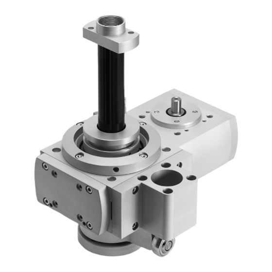
Antriebswelle für Drehbewegung è zur Befestigung ( Kapitel 5 Einbau mechanisch") Gewindebohrungen für Axialbausatz zur Motoranbindung Durchgangsbohrungen zur Befestigung (nur bei EHMB−25/32) Halter mit Durchgangsbohrungen zur Zylinderanbindung (beiliegend) Nutwellenführung Gelenkkopf (beiliegend) und Anschlussbolzen für Linearbewegung Anschlagmutter Festo EHMB 1008a Deutsch... -
Page 5: Funktion Und Anwendung
Haltebremse oder mit hohem Eigenhaltemoment erzielt werden. Hinweis Ohne Anschlagmutter 5 und Linearantrieb kann die Welle 4 aus dem Lager des EHMB rutschen. Dann ist eine Reparatur durch Festo erforderlich. · Stellen Sie sicher, dass bei demontiertem Linearantrieb die Anschlagmutter nicht entfernt wird. -
Page 6: Transport Und Lagerung
Hinweis Die Positionierzeiten und zulässigen Massenträgheitsmomente am Antrieb sind stark abhängig vom angeflanschten Motor. · Verwenden Sie das Auslegungstool PositioningDrives" von Festo zur Auslegung der optimalen Kombination der Produkte (è www.festo.com). Sorgen Sie für die Einhaltung der folgenden Vorgaben: ·... -
Page 7: Einbau
Dabei ist der Gelenkkopf so zu justieren, dass er beim Anbau des Zylinderhalters auf den Anschlussbolzen am EHMB passt und das Maß X (è Bild 5) eingehalten wird. EHMB−... +0,5 +0,5 +0,5 Maß X [mm] 11,5 Bild 5 Bild 6 Festo EHMB 1008a Deutsch... - Page 8 Exzentrische Massen können das Lager zerstören. · Berücksichtigen Sie, dass die vordere Seite (A) (è Bild 9) nur für den Anbau mit einer symmetrischen Zusatzmasse zulässig ist. · Platzieren Sie das EHMB so, dass Ihre Bedienteile erreichbar sind. Festo EHMB 1008a Deutsch...
- Page 9 · Stellen Sie sicher, dass das EHMB nur durch Motoren mit einer federbelasteten Haltebremse betrieben wird. · Prüfen Sie, ob Sicherungsmaßnahmen gegen Schäden durch Zahnriemenbruch zusätzlich extern erforderlich sind (z. B. Zahnklinken oder bewegte Bolzen). Dadurch vermeiden Sie, dass die Nutzlast herabfällt. Festo EHMB 1008a Deutsch...
-
Page 10: Einbau Elektrisch
(D è Bild 16) zunächst leicht ein. Nach endgültiger Positionierung mit Anziehdrehmoment: 0,7 Nm. · Drehen Sie die Näherungsschalter (E) in den Sensorhalter (F) ein. Bild 14 Bei Bedarf kann der Sensorhalter um 90° (EHMB−20/32) bzw. 180° (EHMB−25) versetzt montiert werden. Festo EHMB 1008a Deutsch... -
Page 11: Einbau Schaltungstechnisch
Beim Einsatz in sicherheitsrelevanten Applikationen sind zusätzliche Maßnahmen notwendig. In Europa z. B. die Beachtung der unter der EG−Maschinenrichtlinie gelisteten Normen. Ohne zusätzliche Maßnahmen entsprechend gesetzlich vorgegebener Mindestanforderungen ist das Produkt nicht als sicherheitsrelevantes Teil von Steuerungen geeignet. Festo EHMB 1008a Deutsch... -
Page 12: Inbetriebnahme
· Prüfen Sie, ob mechanische oder elektrische Sicherungsmaßnahmen erforderlich sind. 1. Kontrollfahrt 2. Referenzfahrt 3. Probefahrt Ermittlung der Dreh/Hub− Abgleich der Realsituation mit Prüfung des richtung des Motors dem Abbild in der Steuerung Gesamtverhaltens Bild 18: Definitionen Festo EHMB 1008a Deutsch... -
Page 13: Inbetriebnahme Durchführung
Nur bei völligem Stillstand der Masse darf ein Greifen an das EHMB möglich sein. Hinweis Bei der Demontage des Motors, der Schaltnocken und des Elektrozylinders DNCE geht die Referenzposition verloren. · Starten Sie eine Referenzfahrt gemäß Kapitel Inbetriebnahme", um die Referenzposition neu zu bestimmen. Festo EHMB 1008a Deutsch... -
Page 14: Wartung Und Pflege
· Montieren Sie die Nockenaufnahme (H) wieder. Das Anziehdrehmoment des Gewindestifts beträgt 1 Nm. · Prüfen Sie, ob die Näherungsschalter wie gewünscht schalten. · Korrigieren Sie ggf. die Position der Nocken (è Kapitel 5 Einbau elektrisch"). Festo EHMB 1008a Deutsch... -
Page 15: Reparatur
2. Wiederholen Sie die Inbetriebnahme. Reparatur Empfehlung: · Schicken Sie das Produkt an unseren Reparaturservice. Dadurch werden erforderliche Feinabstimmungen und Prüfungen besonders berücksichtigt. Zubehör Hinweis · Wählen Sie bitte das entsprechende Zubehör aus unserem Katalog www.festo.com/catalogue Festo EHMB 1008a Deutsch... -
Page 16: Störungsbeseitigung
Störung Mögliche Ursache Abhilfe Quietsch− Falsche Reglereinstellungen Reglerparameter ändern geräusche oder geräusche oder Überlastung/Materialermüdung EHMB zur Reparatur an Festo senden Vibrationen Stoßdämpfer defekt (bei Verwendung Stoßdämpfer wechseln eines pneumatischen Zylinders DNC) Dreh−Hub−Modul Belastungen zu hoch Lastmasse reduzieren bewegt sich bewegt sich... -
Page 17: Technische Daten
< 3700 moment der Nutzlast Abtriebsmoment abzüglich Reibung ist drehzahlabhängig Bei maximaler Drehzahl Zylinderabhängig; Werte mit DNC−32/40 Motorabhängig; Werte mit Motor MTR−DCI−...−G14 Horizontaler Einsatz (bei vertikalem Einsatz und symmetrischer, nicht exzentrischer Anordnung bis 15 kg möglich) Festo EHMB 1008a Deutsch... - Page 18 Abtriebsmoment abzüglich Reibung ist drehzahlabhängig Bei maximaler Drehzahl Zylinderabhängig; Werte mit DNC−32/40 Motorabhängig; Werte mit Motor MTR−DCI−...−G14 Horizontaler Einsatz (bei vertikalem Einsatz und symmetrischer, nicht exzentrischer Anordnung bis 15 kg möglich) Bild 22 Kennlinien (am Ende der Bedienungsanleitung) Festo EHMB 1008a Deutsch...
- Page 19 ......... . Festo EHMB 1008a English...
-
Page 20: Control Sections And Connections
Threaded holes for axial kit for connecting Through−holes for mounting (only for the motor EHMB−25/32) Retainer with through−holes for connecting Grooved shaft guide the cylinder (supplied) Rod eye (supplied) and connecting bolts for Stop nut linear motion Festo EHMB 1008a English... -
Page 21: Function And Application
EHMB. Then a repair by Festo is required. · If the linear drive is dismantled, make sure that the stop nut is not removed. · Use the related motors from Festo (è catalogue specification, www.festo.com/catalogue). You will then be operating mating devices, which are especially adapted to each other. -
Page 22: Transport And Storage
The positioning times and permitted mass moments of inertia on the drive depend to a large extent on the flange−mounted motor. · Use the design tool Positioning Drives" from Festo to determine the optimum combination of products (è www.festo.com). Make sure that the following specifications are observed: ·... -
Page 23: Installation
EHMB and the dimension X (è Fig. 5) is observed. EHMB−... Fig. 5 +0.5 +0.5 +0.5 Dimen [mm] 11.5 sion X Fig. 6 Festo EHMB 1008a English... - Page 24 · Position the EHMB so that your control sections are accessible. · Fasten the EHMB to the threaded hole with 4 screws and 2 centring sleeves or with the aid of kits. Festo EHMB 1008a English...
- Page 25 · Check whether external safety measures against damage due to a toothed−belt break are also necessary (e.g. toothed latches or moving bolts). In this way you can prevent the effective load from sliding down. Festo EHMB 1008a English...
-
Page 26: Electrical Installation
After final positioning with tightening torque: 0.7 Nm. · Screw the proximity sensor (E) into the sensor bracket (F). If necessary, the sensor bracket can be mounted off−set by 90° (EHMB−20/32) Fig. 14 or 180° (EHMB−25). Festo EHMB 1008a English... -
Page 27: Installing Circuitry
In Europe, for example, the standards in the EC machinery directive must be observed. Without additional measures in accordance with statutory minimum requirements, the product is not suitable for use as a safety−related part of control systems. Festo EHMB 1008a English... -
Page 28: Commissioning
· Check whether mechanical or electric safety measures are necessary. 1. Check travel 2. Homing 3. Test run Determining the rotation/stroke Comparing the real situation Checking the direction of the motor with the image in the controller overall behaviour Fig. 18: Definitions Festo EHMB 1008a English... -
Page 29: Carrying Out Commissioning
Note The homing position is lost when the motor, trip cam or DNCE electric cylinder is removed. · Start homing in accordance with the chapter Commissioning" in order to determine the new homing position. Festo EHMB 1008a English... -
Page 30: Service And Maintenance
Reassemble the cam fixture (H). The tightening torque of the threaded pin is 1 Nm. · Check whether the proximity sensors operate as desired. · Correct the position of the cams, if necessary (è chapter 5 Electrical installation") Festo EHMB 1008a English... -
Page 31: Repair
2. Repeat the commissioning. Repair Recommendation: · Send the product to our repair service. The necessary fine adjustments and tests will then be taken especially into account. Accessories Note · Please select the appropriate accessories from our catalogue www.festo.com/catalogue Festo EHMB 1008a English... -
Page 32: Eliminating Malfunctions
Grease gun with needle point nozzle 647 958 LUB−1 Lubrication adapter 705 639 LUB−1−TR Roller bearing grease LUB−KB2 from Festo See spare parts catalogue at www.festo.com/spareparts Fig. 20 Eliminating malfunctions Malfunction Possible cause Remedy Squeaking noises Incorrect regulator settings Change the regulator parameters... -
Page 33: Technical Data
Driving torque minus friction depends on speed At maximum speed Cylinder−dependent; values with DNC−32/40 Motor−dependent; values with motor MTR−DCI−...−G14 Horizontal use (for vertical use and symmetric, not−eccentric configuration up to 15 kg possible) Festo EHMB 1008a English... -
Page 34: Characteristic Curves
At maximum speed Cylinder−dependent; values with DNC−32/40 Motor−dependent; values with motor MTR−DCI−...−G14 Horizontal use (for vertical use and symmetric, not−eccentric configuration up to 15 kg possible) Fig. 22 Characteristic curves (at the end of the operating instructions) Festo EHMB 1008a English... - Page 35 ......... Festo EHMB 1008a Español...
-
Page 36: Elementos De Mando Y Conexiones
Taladro pasante de fijación Soporte con taladros pasantes para la (sólo en EHMB−25/32) conexión del cilindro (adjunto) Guía de eje nervado Cabeza de rótula (adjunto) y bulón de conexión para movimiento lineal Tuerca de tope Festo EHMB 1008a Español... -
Page 37: Funcionamiento Y Aplicación
Sin la tuerca de tope 5 y sin accionamiento lineal, el eje 4 puede salirse del casquillo de bolas del EHMB. En este caso deberá ser reparado por Festo. · Asegúrese de que cuando el accionamiento lineal esté desmontado no se retire la tuerca de tope. -
Page 38: Transporte Y Almacenamiento
Los tiempos de posicionamiento y los momentos de inercia permitidos en el accionamiento dependen en gran parte del motor acopiado. · Utilice la herramienta de configuración Positioning Drives" de Festo para configurar la combinación óptima de los productos (è www.festo.com). -
Page 39: Instalación
EHMB y se respete la medida X (è Fig. 5). EHMB−... +0,5 +0,5 +0,5 Medida X [mm] 11,5 Fig. 5 Fig. 6 Festo EHMB 1008a Español... - Page 40 · Coloque el EHMB de forma que todos los elementos de mando sean accesibles. · Fije el EHMB en los taladros roscados con 4 tornillos y 2 casquillos de centraje o sets de ensamble. Festo EHMB 1008a Español...
- Page 41 · Compruebe si es necesario tomar medidas de seguridad adicionales externas para evitar daños provocados por la rotura de la correa dentada (p.ej., trinquetes o bulones móviles). De esta manera se evita la caída de la carga útil. Festo EHMB 1008a Español...
-
Page 42: Instalación Eléctrica
Enrosque el sensor de proximidad (E) en el soporte del detector (F). Si es necesario, el soporte del detector se Fig. 14 puede montar con un giro de 90° (EHMB−20/32) o 180° (EHMB−25). Para ello es necesario realizar los pasos siguientes: Festo EHMB 1008a Español... -
Page 43: Instalación Del Circuito Eléctrico
Si no se toman medidas adicionales como estipulan las exigencias mínimas prescritas por ley, el producto no es apropiado para su uso como pieza relevante para la seguridad en sistemas de mando. Festo EHMB 1008a Español... -
Page 44: Puesta A Punto
1. Recorrido de control 2. Recorrido de referencia 3. Recorrido de prueba Determinación del sentido Ajuste de la situación real a la Verificación del de giro/elevación del motor imagen del sistema de mando comportamiento general Fig. 18: Definiciones Festo EHMB 1008a Español... -
Page 45: Puesta En Funcionamiento
Al desmontar el motor, las levas de mando y el cilindro eléctrico DNCE se pierde la posición de referencia. · Inicie un recorrido de referencia como se indica en el capítulo Puesta a punto" para determinar de nuevo la posición de referencia. Festo EHMB 1008a Español... -
Page 46: Cuidados Y Mantenimiento
Vuelva a montar el alojamiento de la leva (H). El par de apriete del espárrago roscado es de 1 Nm. · Compruebe si los detectores de proximidad conmutan como es debido. · Si es necesario, corrija la posición de las levas (è capítulo 5 Instalación eléctrica"). Festo EHMB 1008a Español... -
Page 47: Reparación
Recomendación: Envíe el producto a nuestro servicio de reparación. De este modo se tienen especialmente en cuenta las operaciones de ajuste de precisión y verificaciones pertinentes. Accesorios Importante · Escoja de nuestro catálogo el accesorio correspondiente: www.festo.com/catalogue Festo EHMB 1008a Español... -
Page 48: Eliminación De Fallos
Ruidos Ajustes del regulador incorrectos Cambiar parámetros del regulador anormales anormales Sobrecarga/fatiga del material Enviar el EHMB a Festo para su reparación o vibraciones Amortiguador averiado (si se Cambiar el amortiguador utiliza un cilindro neumático DNC) El módulo de Cargas demasiado elevadas Reducir la masa de la carga giro y elevación... -
Page 49: Especificaciones Técnicas
Par de salida descontando el rozamiento depende de las revoluciones Con revoluciones máximas Depende del cilindro; valores con DNC−32/40 Depende del motor; valores con motor MTR−DCI−...−G14 Aplicación horizontal (en caso de aplicación vertical y alineación simétrica no excéntrica puede llegar hasta 15 kg) Festo EHMB 1008a Español... -
Page 50: Curvas Características
Depende del cilindro; valores con DNC−32/40 Depende del motor; valores con motor MTR−DCI−...−G14 Aplicación horizontal (en caso de aplicación vertical y alineación simétrica no excéntrica puede llegar hasta 15 kg) Fig. 22 Curvas características (al final del manual de instrucciones) Festo EHMB 1008a Español... - Page 51 ........Festo EHMB 1008a Français...
-
Page 52: Éléments De Commande Et Raccordements
Alésages traversants pour la fixation (uniquement pour l’EHMB−25/32) Support avec alésages traversants pour le raccordement du vérin (fourni) Guidage d’arbre cannelé Chape à rotule (fournie) et boulon de raccordement pour mouvement linéaire Écrou d’arrêt Festo EHMB 1008a Français... -
Page 53: Fonctionnement Et Application
à ressorts ou de couples de maintien élevés. Nota Sans écrou d’arrêt 5 ni actionneur linéaire, l’arbre 4 peut glisser hors du palier de l’EHMB. Cela nécessite alors une réparation par Festo. · S’assurer que l’écrou d’arrêt ne soit pas retiré lorsque l’actionneur linéaire est démonté. -
Page 54: Transport Et Stockage
Nota Les temps de positionnement et moments admissibles d’inertie de masse sur l’actionneur dépendent largement du moteur fixé par brides. · Utiliser l’outil de dimensionnement PositioningDrives" Festo pour le dimensionnement de la combinaison optimale des produits (è www.festo.com). Veiller à respecter les consignes suivantes : ·... -
Page 55: Montage
X (è Fig. 5) soit respectée. EHMB−... Fig. 5 +0,5 +0,5 +0,5 Cote X [mm] 11,5 Fig. 6 Festo EHMB 1008a Français... - Page 56 · Placer l’EHMB de manière à ce que ses organes de commande soient accessibles. · Fixer l’EHMB aux trous taraudés avec 4 vis et 2 douilles de centrage ou à l’aide de kits de fixation. Festo EHMB 1008a Français...
- Page 57 · Vérifier si des mesures de sécurité supplémentaires externes sont nécessaires (p. ex. cliquets de retenue ou goujons mobiles), en cas de rupture de la courroie crantée. Toute chute de la charge utile peut ainsi être évitée. Festo EHMB 1008a Français...
-
Page 58: Montage Électrique
0,7 Nm. · Visser le capteur de proximité (E) dans le support de capteur (F). Fig. 14 Si nécessaire, le support de capteur peut être installé avec un décalage de 90° (EHMB−20/32) ou 180° (EHMB−25). Festo EHMB 1008a Français... -
Page 59: Principe De Raccordement
En Europe, p. ex., il convient de respecter les normes énumérées dans la directive CE sur les machines. Sans mesure supplémentaire conforme aux exigences minimales spécifiées par la loi, le produit ne peut pas être utilisé en tant que composant de sécurité des commandes. Festo EHMB 1008a Français... -
Page 60: Mise En Service
2. Déplacement 3. Déplacement de contrôle de référence d’essai Définition du sens de Comparaison entre la situation ré Contrôle de la réaction rotation/de course du elle et la représentation dans la globale moteur commande Fig. 18: Définitions Festo EHMB 1008a Français... -
Page 61: Réalisation De La Mise En Service
Lors du démontage du moteur, des cames de commutation et du vérin électrique DNCE, la position de référence est perdue. · Lancer un déplacement de référence conformément au chapitre Mise en service", pour définir à nouveau la position de référence. Festo EHMB 1008a Français... -
Page 62: Maintenance Et Entretien
Remonter le logement de cames (H). Le couple de serrage de la vis sans tête est de 1 Nm. · Vérifier que les capteurs de proximité commutent correctement. · Corriger, le cas échéant, la position des cames (è Chapitre 5 Montage électrique"). Festo EHMB 1008a Français... -
Page 63: Réparation
2. Effectuer une nouvelle mise en service. Réparation Recommandation : · Envoyer le produit à notre service de réparation. Les réglages de précision et contrôles nécessaires pourront ainsi être effectués. Accessoires Nota · Sélectionner les accessoires correspondants dans notre catalogue www.festo.com/catalogue Festo EHMB 1008a Français... -
Page 64: 11 Dépannage
Pompe à graisse avec gicleur tête d’aiguille 647 958 LUB−1 Adaptateur de graissage 705 639 LUB−1−TR Graisse pour roulement LUB−KB2 de Festo Voir le catalogue des pièces de rechange sous www.festo.com/spareparts Fig. 20 Dépannage Panne Cause possible Remède Grincements ou Réglages incorrects du régulateur Modifier les paramètres du régulateur... -
Page 65: Caractéristiques Techniques
Le couple de sortie sans frottement dépend de la vitesse Pour vitesse de rotation maximale Selon le vérin ; valeurs avec DNC−32/40 Selon le moteur ; valeurs avec moteur MTR−DCI−...−G14 Utilisation horizontale (en cas d’utilisation verticale et de disposition symétrique, non excentrée, jusqu’à 15 kg) Festo EHMB 1008a Français... - Page 66 Selon le vérin ; valeurs avec DNC−32/40 Selon le moteur ; valeurs avec moteur MTR−DCI−...−G14 Utilisation horizontale (en cas d’utilisation verticale et de disposition symétrique, non excentrée, jusqu’à 15 kg) Fig. 22 Courbes caractéristiques (à la fin de la notice d’utilisation) Festo EHMB 1008a Français...
- Page 67 ......... . Festo EHMB 1008a Italiano...
-
Page 68: Elementi Di Comando E Attacchi
Fori passanti per fissaggio collegamento del motore (solo per EHMB−25/32) Supporto con fori passanti per Guida ad albero scanalato collegamento del cilindro (in dotazione) Testa a snodo (in dotazione) e perno di Dado di arresto attacco per movimento lineare Festo EHMB 1008a Italiano... -
Page 69: Funzione E Applicazione
Nota Senza dado di arresto 5 e attuatore lineare, l’albero 4 può fuoriuscire dal cuscinetto dell’EHMB. In questo caso il modulo deve essere riparato da Festo. · Non rimuovere il dado di arresto quando l’attuatore lineare è smontato. ·... -
Page 70: Trasporto E Stoccaggio
I tempi di posizionamento e i momenti di inerzia di massa ammissibili sull’attuatore dipendono fortemente dal motore fissato a flangia. · Per il dimensionamento della combinazione ottimale dei prodotti utilizzare il tool PositioningDrives" Festo (è www.festo.com). Garantire l’osservanza delle seguenti condizioni: ·... -
Page 71: Montaggio
EHMB quando si monta il supporto del cilindro sul perno di attacco e che la misura X (è Fig. 5) venga osservata. EHMB−... +0,5 +0,5 +0,5 Misura X [mm] 11,5 Fig. 5 Fig. 6 Festo EHMB 1008a Italiano... - Page 72 · Posizionare il modulo EHMB in modo che tutti gli elementi operativi siano accessibili. · Fissare l’EHMB sui fori filettati con 4 viti e 2 bussole di centraggio oppure utilizzando dei kit. Festo EHMB 1008a Italiano...
- Page 73 · Verificare l’opportunità di adottare misure supplementari di sicurezza contro una rottura della cinghia dentata nella parte esterna (ad es. nottolini o perni mobili). In tal modo si evita la caduta del carico. Festo EHMB 1008a Italiano...
-
Page 74: Montaggio Dei Componenti Elettrici
0,7 Nm. · Avvitare i sensori di finecorsa (E) nel supporto (F). Fig. 14 Il supporto può essere montato anche in posizione spostata di 90° (EHMB−20/32) o 180° (EHMB−25). Festo EHMB 1008a Italiano... -
Page 75: Montaggio Dei Circuiti
In Europa ad es. l’osservanza delle norme elencate nella direttiva CE sui macchinari. Il prodotto non è adatto come parte essenziale per la sicurezza di sistemi di comando se non vengono adottate misure supplementari secondo i requisiti minimi previsti dalla legge. Festo EHMB 1008a Italiano... -
Page 76: Messa In Funzione
1. corsa di controllo 2. corsa di riferimento 3. corsa di prova Determinazione del Regolazione della situazione reale Controllo del senso di rotazione/corsa in base alla rappresentazione nel comportamento del motore sistema di comando generale Fig. 18: Definizioni Festo EHMB 1008a Italiano... -
Page 77: Esecuzione Della Messa In Funzione
La posizione di riferimento va persa smontando il motore, le camme di commutazione e il cilindro elettrico DNCE. · Eseguire una corsa di riferimento secondo il cap. Messa in funzione" per ridefinire la posizione di riferimento. Festo EHMB 1008a Italiano... -
Page 78: Manutenzione
Rimontare la sede della camma (H). La coppia di serraggio del perno filettato è 1 Nm. · Controllare se i sensori di finecorsa commutano come desiderato. · Eventualmente correggere la posizione delle camme (è cap. 5 Montaggio dei componenti elettrici"). Festo EHMB 1008a Italiano... -
Page 79: Riparazione
2. Ripetere la messa messa in funzione. Riparazione Suggerimento: · Inviare l’unità al servizio assistenza per riparazioni Festo. Così verranno eseguite soprattutto le microregolazioni e le verifiche necessarie. Accessori Nota · Scegliere gli appositi accessori nel catalogo Festo www.festo.com/catalogue... -
Page 80: Eliminazione Di Anomalie
Ingrassatore a siringa con bocchetta a punta d’ago 647 958 LUB−1 Adattatore di lubrificazione 705 639 LUB−1−TR Grasso per cuscinetti volventi LUB−KB2 Festo Vedi catalogo parti di ricambio all’indirizzo www.festo.com/spareparts Fig. 20 Eliminazione di anomalie Anomalia Eventuale causa Intervento Rumori stridenti Regolazioni errate del regolatore... -
Page 81: Dati Tecnici
DNC−32/40 in funzione del motore; valori con motore MTR−DCI−...−G14 impiego orizzontale (è possibile fino a 15 kg in caso di impiego verticale e disposizione simmetrica non eccentrica) Festo EHMB 1008a Italiano... - Page 82 DNC−32/40 in funzione del motore; valori con motore MTR−DCI−...−G14 impiego orizzontale (è possibile fino a 15 kg in caso di impiego verticale e disposizione simmetrica non eccentrica) Fig. 22 Curve caratteristiche (in appendice alle istruzioni d’uso) Festo EHMB 1008a Italiano...
- Page 83 ............Festo EHMB 1008a Svenska...
-
Page 84: Manöverdon Och Anslutningar
Centreringshål och gängade hål för è montering ( kapitel 5 Mekanisk Gängade hål för axialbyggsats för montering") motoranslutning Genomgående fästhål (endast för Hållare med genomgående hål för EHMB−25/32) cylinderanslutning (bifogad) Spåraxelstyrning Länkstångshuvud (bifogat) och anslutningsskruv för linjärrörelse Anslagsmutter Festo EHMB 1008a Svenska... -
Page 85: Funktion Och Användning
Information Utan anslagsmutter 5 och linjärenhet kan axeln 4 glida ur EHMB:s lager. Då krävs reparation som utförs av Festo. · Se till att anslagsmuttern inte tas bort när linjärenheten är demonterad. · Använd tillhörande motorer från Festo (è kataloguppgifter, www.festo.com/catalogue). -
Page 86: Transport Och Lagring
Bild 2 Information Positioneringstiderna och de tillåtna masströghetsmomenten på drivenheten beror till stor del på den påmonterade motorn. · Använd dimensioneringsverktyget PositioningDrives" från Festo för att kombinera produkterna optimalt (è www.festo.com). Var noga med att följa anvisningarna i följande punkter: ·... -
Page 87: Montering
Bild 4 Justera länkstångshuvudet så att det passas in mot anslutningsskruven på EHMB när cylinderhållaren monteras och att måttet X (è Bild 5) erhålls. EHMB−... +0,5 +0,5 +0,5 Mått X [mm] 11,5 Bild 5 Bild 6 Festo EHMB 1008a Svenska... - Page 88 · Observera att framsidan (A) (è Bild 9) endast får användas för montering med symmetrisk belastning. · Montera EHMB så att du kan nå manöverdelarna. · Fäst EHMB i de gängade hålen med 4 skruvar och 2 centreringshylsor eller med hjälp av byggsatser. Festo EHMB 1008a Svenska...
- Page 89 · Säkerställ att EHMB endast drivs av Bild 11 motorer med en fjäderbelastad hållbroms. · Kontrollera om det krävs ytterligare externa säkerhetsåtgärder mot skador vid kuggremsbrott (t ex kugghakar eller rörliga bultar). På så sätt kan man förhindra att arbetslasten faller ned. Festo EHMB 1008a Svenska...
-
Page 90: Elektrisk Montering
Skruva först i gängstiften (D è Bild 16) lätt. Efter slutgiltig positionering med åtdragningsmoment: 0,7 Nm. · Skruva i lägesgivarna (E) i givarfästet (F). Vid behov kan givarfästet monteras med 90° (EHMB−20/32) resp 180° (EHMB−25) förskjutning. Bild 14 Festo EHMB 1008a Svenska... -
Page 91: Kopplingsteknisk Montering
Vid användning i säkerhetsapplikationer krävs ytterligare åtgärder. I Europa måste t ex de standarder som anges i EG−maskindirektivet följas. Om inga ytterligare åtgärder vidtas enligt föreskrivna minimikrav lämpar sig inte produkten som säkerhetsrelevant del av styrsystem. Festo EHMB 1008a Svenska... -
Page 92: Idrifttagning
Det kan leda till att laster som hålls fast ramlar ned (t ex om slangen till ett pneumatiskt gripdon lossnar). · Kontrollera om mekaniska eller elektriska säkerhetsåtgärder behöver vidtas. 1. Kontrollkörning 2. Referenskörning 3. Provkörning Fastställande av motorns Den verkliga applikationen jämförs Övergripande rotations−/slagriktning med styrsystemets inställning funktionskontroll Bild 18: Definitioner Festo EHMB 1008a Svenska... -
Page 93: Idrifttagning
Endast när massan är helt stilla får det vara möjligt att komma åt EHMB. Information Vid demontering av motorn, kamskivan och elcylindern DNCE förloras referenspositionen. · Bestäm den nya referenspositionen genom att starta en referenskörning enligt kapitlet Idrifttagning". Festo EHMB 1008a Svenska... -
Page 94: Underhåll Och Skötsel
Annars fylls inte fettutrymmena jämnt. · Montera kamfästet (H) igen. Åtdragningsmomentet för gängstiftet är 1 Nm. · Kontrollera att lägesgivarna kopplar om som de ska. · Korrigera kammarnas läge vid behov (è kapitel 5 Elektrisk montering"). Festo EHMB 1008a Svenska... -
Page 95: Reparation
På så sätt kommer en annan del av kuggremmen in i kugghjulens belastningszon. 2. Upprepa idrifttagningen. Reparation Rekommendation: · Skicka produkten till vår reparationsservice. På så sätt säkerställs att nödvändiga finjusteringar och kontroller genomförs. Tillbehör Information · Välj rätt tillbehör från vår katalog www.festo.com/catalogue Festo EHMB 1008a Svenska... -
Page 96: Åtgärdande Av Fel
Möjlig orsak Åtgärd Gnisselljud eller Fel regulatorinställningar Ändra regulatorparametrar vibrationer vibrationer Överbelastning/materialutmattning Skicka EHMB till Festo för reparation Stötdämpare defekt (vid användning Byt stötdämparen av pneumatisk cylinder DNC) Vrid−/slagenheten För hög belastning Reducera lastmassan rör sig inte rör sig inte Reducera rörelsehastigheten... -
Page 97: Tekniska Data
Utgående moment minus friktion är varvtalsberoende Vid maximalt varvtal Cylinderberoende; värden med DNC−32/40 Motorberoende; värden med motor MTR−DCI−...−G14 Horisontell användning (vid vertikal användning och symmetrisk, icke−excentrisk placering är det möjligt med upp till 15 kg) Festo EHMB 1008a Svenska... -
Page 98: Kurvor
Vid maximalt varvtal Cylinderberoende; värden med DNC−32/40 Motorberoende; värden med motor MTR−DCI−...−G14 Horisontell användning (vid vertikal användning och symmetrisk, icke−excentrisk placering är det möjligt med upp till 15 kg) Bild 22 Kurvor (i slutet av bruksanvisningen) Festo EHMB 1008a Svenska... -
Page 99: Kennlinien
IT: Forza dimanica max. Fx e Fy in funzione della distanza y e z SV: Max. dynamisk kraft Fx och Fy relaterat till avståndet y och z EHMB−20 EHMB−25 EHMB−32 | Fy | | Fx | | Fz | + Fy Festo EHMB 1008a... - Page 100 FR : Flèche f en fonction de la force radiale F et de la course l IT: Inflessione f in funzione della forza trasversale F e della corsa l SV: Nedböjning f i förhållande till tvärkraften F och slaglängden l EHMB−20 l = 10 mm l = 200 mm EHMB−25 Festo EHMB 1008a...
- Page 101 EHMB EHMB−32 l = 10 mm l = 200 mm Festo EHMB 1008a...
- Page 102 FR : Vitesse max. v en fonction de la charge utile m (vérin DNC) IT: Velocità max. v in funzione del carico utile m (cilindro DNC) SV: Max hastighet v i förhållande till arbetslasten m (DNC−cylinder) EHMB−20 EHMB−25 EHMB−32 (DYSW 1x) EHMB−32 (DSYW 2x) Festo EHMB 1008a...
- Page 103 EHMB Festo EHMB 1008a...
- Page 104 Copyright: autorisation écrite expresse. Tout manquement à cette © Festo AG & Co. KG, règle est illicite et expose son auteur au versement de Postfach dommages et intérêts. Tous droits réservés pour le cas de D−73726 Esslingen...
Need help?
Do you have a question about the EHMB Series and is the answer not in the manual?
Questions and answers