Table of Contents
Advertisement
Quick Links
Advertisement
Table of Contents

Related Manuals for Epever MSC-N Series


Summary of Contents for Epever MSC-N Series
- Page 1 MPPT Solar Charge Controller User Manual MSC2210N MSC3210N MSC4210N MSC4215N...
-
Page 3: Table Of Contents
Contents Important Safety Instructions 1 General Information 1.1 Overview 1.2 Appearance 1.3 Naming rules 1.4 Connection diagram 1.4.1 Battery mode 1.4.2 No-battery mode 2 Interface 2.1 Indicator 2.2 Button 2.3 Battery type 2.4 Battery voltage control parameters 2.5 Load output voltage and priority setting 2.6 Load operation mode 3 Installation 3.1 Attentions... - Page 4 4.3 Maintenance 5 Specifications Annex I PV Conversion Efficiency Curves Annex 2 Load Conversion Efficiency Curves...
-
Page 5: Important Safety Instructions
Important Safety Instructions Please reserve this manual for future review. This manual contains all safety, installation, and operation instructions for the MSC-N series Security Monitoring Maximum Power Point Tracking (MPPT) solar controller ("controller" as referred to in this manual). 1. Explanation of symbols Please read related literature accompanying symbols to enable users to use the product efficiently and ensure personal and property safety. - Page 6 Install the controller to a specified location; Conduct trial operations for the controller; Operate and maintain the controller 4. Safety cautions before installation When you receive the controller, check whether any damage occurred in transportation. Contact the transportation company IMPORTANT or our company in time for any problem.
- Page 7 WARNING SURFACE 8. Dangerous operations which would cause an electric arc, fire, or explosion Touch the wire end that hasn't been insulation treated and may be electriferous. Touch the wiring copper row, terminals, or internal modules of the controller that may be electriferous.
-
Page 8: General Information
1 General Information 1.1 Overview MSC-N series is a new generation of solar controllers with a two-way load output. An enable switch allows the two-way load output voltage to switch to 12V or 24V DC. According to the battery voltage, the two-way load output voltage can be turned off in stages to ensure the main load output. - Page 9 Accurate recognizing and tracking technology of multi-peaks maximum power point Wider MPP running voltage to increase the utilization ratio of PV modules Support the lead-acid and lithium batteries, programmable temperature compensation High temperature charging automatic power reduction function ...
-
Page 10: Appearance
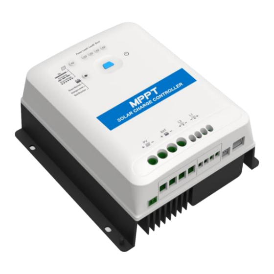
1.2 Appearance ① ⑨ Power Indicator Load 2 Terminals ② ⑩ Load 1 indicator Grounding terminal Temperature sensor ③ ⑪ Load 2 indicator ② interface ④ ⑫ Error codes PV Terminals Load ON/OFF and setting ⑤ ⑬ Battery Terminals button Load 1/Load 2/Prior Mode ⑥... -
Page 11: Naming Rules
Definition Instruction +5VDC 5V/200mA RS485-B RS485-B RJ45 crystal head RS485-A RS485-A Power GND Do not short circuit the positive and negative pins of the RS485 communication port; otherwise, it will damage the controller. WARNING ② If the remote temperature sensor is not connected to the controller or damaged, the controller will charge or discharge the battery at the default temperature setting of 25℃... -
Page 12: Connection Diagram
1.4 Connection diagram 1.4.1 Battery mode 1.4.2 No-battery mode The PV array will provide power for the load in the no-battery mode. The operating processes of setting the no-battery way by the controller button are shown below: Step1: Press the controller button for 5s until the indicator blinks orange slowly. - Page 13 30V, will the load work normally. In the condition of a two-way load, when the power of the PV array is lower than the total power of the loads but can meet the power of load 2, the output of load 2 is given priority. Load 1 will be turned off and restarted every 30 minutes until it can work normally.
-
Page 14: Interface
2 Interface 2.1 Indicator Indicator Color Status Definition PV charges the battery with a low Green ON solid current 1. No sunlight 2. Connection error Green 3. Low PV voltage Slowly Green Normal charging Flashing(1Hz) Fast Flashing PV over voltage (4Hz) Green ON solid... -
Page 15: Button
ON solid Battery over discharged Slowly Battery over temperature Flashing(1Hz) Fast Flashing Lithium battery low temperature① (4Hz) Controller normal ON solid Battery type: 12V Sealed Green Slowly Battery type: 24V Sealed Flashing Load 1 ON ON solid Battery type: 12V Gel Green Slowly Battery type: 24V Gel... -
Page 16: Battery Type
Press for 5s Enter the Battery type setting interface 2.3 Battery type ① Supported battery types Sealed (default, 12V Sealed/24V Sealed) Lead-acid Gel (12V Gel/24V Gel) battery LiFePO4 (12V LFP/24V LFP) Lithium Li(NiCoMn)O2 (12V LNCM/24V LNCM) battery User ② Setting the battery type by the controller button Step1: Press the controller button for 5s until the indicator blinks orange slowly. - Page 17 Battery type Sealed User Voltage parameters Over Voltage 16.0V 16.0V 9~17V Disconnect Voltage Charging Limit 15.0V 15.0V 9~17V Voltage Over Voltage 15.0V 15.0V 9~17V Reconnect Voltage Equalize Charging 14.6V 9~17V Voltage Boost Charging 14.4V 14.2V 9~17V Voltage Float Charging 13.8V 13.8V 9~17V Voltage...
- Page 18 Charging Voltage. B. Over Voltage Disconnect Voltage > Over Voltage Reconnect Voltage C. Low Voltage Reconnect Voltage > Low Voltage Disconnect Voltage ≥ Discharging Limit Voltage. D. Under Voltage Warning Reconnect Voltage>Under Voltage Warning Voltage≥ Discharging Limit Voltage; E. Boost Reconnect Charging voltage >Low Voltage Reconnect Voltage. ...
-
Page 19: Load Output Voltage And Priority Setting
A. Over Voltage Disconnect Voltage>Over Charging Protection Voltage(Protection Circuit Modules(BMS))+0.2V; B. Over Voltage Disconnect Voltage>Over Voltage Reconnect Voltage=Charging Limit Voltage ≥ Equalize Charging Voltage = Boost Charging Voltage ≥ Float Charging Voltage>Boost Reconnect Charging Voltage; C. Low Voltage Reconnect Voltage > Low Voltage Disconnect Voltage ≥ Discharging Limit Voltage. -
Page 20: Load Operation Mode
Output voltage Set to ON Output 24V Load working CPM(Charging Prior Mode) Set to OFF Modes (Default) CPM/LPM (only valid for load ① Set to ON LPM(Load prior mode ① The load prior mode will be enabled when the battery voltage reaches the low voltage disconnect voltage and the PV array charging current reaches more than 7A for 10 minutes. - Page 21 five minutes and then turned off for ten minutes. The load output will resume when the battery voltage reaches the Low Voltage Reconnect Voltage. Mode 2: The load output will be turned off when the battery voltage reaches the Low Voltage Disconnect Voltage.
-
Page 22: Installation
3 Installation 3.1 Attentions Be very careful when installing the batteries. Please wear eye protection when installing the open-type lead-acid battery, and rinse with clean water in time for any contact with battery acid. Keep the battery away from any metal objects, which may cause a short circuit of the battery. - Page 23 According to the open-circuit voltage (VOC) and the maximum power point voltage (VMPP) of the MPPT controller, the serial connection of PV modules suitable for different controllers can be calculated. The below table is for reference only. MSC2210N/MSC3210N/MSC4210N: 36cell 48cell 54cell 60cell System...
-
Page 24: Wire Size
3.3 Wire size The wiring and installation methods must conform to the national and local electrical code requirements. PV wire size The PV array output varies with the PV module's size, connection method, and sunlight angle. The PV array's short circuit current(ISC) can calculate the minimum PV wire size. -
Page 25: Mounting
MSC4210N 16mm /6AWG MSC4215N The wire size is only for reference. Suppose there is a long distance between the PV array, the controller, and the battery. In that case, larger wires shall be used to reduce the voltage drop and improve the system performance. - Page 26 Step 1: Determine the installation location and heat-dissipation space The controller requires at least 150mm of clearance above and below for proper airflow, as shown below. Air outlet Air inlet Suppose the controller is to be installed in an enclosed box. In that case, ensuring reliable heat-dissipation through the box is CAUTION important.
- Page 27 Step 3:Grounding MSC-N series are common-negative controllers; all the negative terminals can be grounded simultaneously, or anyone is grounded. However, according to the practical application, the negative terminals of the PV array, battery, and load can also be ungrounded.
- Page 28 A common-negative controller for a common-negative system, such as the RV system, is recommended. The controller may be damaged if a common-positive controller is used and the positive CAUTION electrode is grounded in the common-negative system. Step 4:Connect the remote temperature sensor Connect the remote temperature sensor to interface ⑪...
-
Page 29: Others
4 Others 4.1 Protection Protection Instruction PV limit When the charging current/power of the PV array exceeds Current/limit power the rated charging current/power, the PV array will charge protection the battery as per the rated charging current/power. PV short circuit When not in the PV charging state, the controller will not be protection damaged in the case of a short-circuiting in the PV array. - Page 30 The controller detects the battery temperature through an Battery overheating external temperature sensor. The battery will stop working protection when its temperature exceeds 65 ° C and will resume when it is below 55 ° C. When the detected temperature is lower than the Low Temperature Protection Threshold (LTPT), the controller Lithium battery low- automatically stops charging and discharging.
-
Page 31: Troubleshooting
For example MSC4215N 24V system: 4.2 Troubleshooting Possible Faults Solutions reasons Charging LED is OFF during daytime PV array open Confirm whether the PV array when sunshine falls circuit connection is correct and tight on PV array properly The wire connection is Please check the battery's voltage Battery voltage is... - Page 32 The battery While the temperature declines Battery indicator flashes below 55 º C, the controller will overheating red slowly resume. When the heat sink of the controller exceeds 85℃, the controller will Controller automatically cut off the input and overheating output circuit.
- Page 33 4.3 Maintenance The following inspections and maintenance tasks are recommended at least twice yearly for the best performance. Make sure no block on airflow around the controller. Clear up any dirt and fragments on the radiator. Check all the naked wires to ensure insulation is not damaged by sun exposure, frictional wear, dryness, insects or rats, etc.
- Page 34 5 Specifications Electrical Parameters Model MSC2210N MSC3210N MSC4210N MSC4215N 12/24VDC ★ Auto- Battery rated 24VDC 24VDC voltage recognition Rated charging current Controller working voltage 8~32V 8~32V 16~32V 16~32V range 150V(At minimum operating 100V(At minimum operating environment environment Max. PV open temperature) temperature) circuit voltage...
- Page 35 Load rated Load 1: 100W power Load 2: 36W Load 1: Under Voltage Warning Voltage (it can be set when Load output the battery type is "USER.") protection Load 2: Low Voltage disconnect Voltage (it can be set when voltage the battery type is "USER.") Max.
- Page 36 PV limit current/ limit power/short circuit/reverse /night reverse charging protection Lithium Battery reverse/over voltage/over- Protections discharging/overheating/low temperature charging and discharging protection Load short circuit/overload protection, controller overheating protection, against transient ★ When an LFP or LNCM battery is used, the system voltage can't be identified automatically.
- Page 37 enabled. Details refer to 4.1 protections. When the working environment temperature exceeds 50° C, the actual load power needs to be derated. With every increase of 1° C, the actual load power needs to be reduced by 2.57% of the rated load power. For example, when the working temperature reaches 60℃, the actual rated power for load 1 will be 100W-0.0257*(60-50)*100=74.3W.
- Page 38 Annex I PV Conversion Efficiency Curves Test condition: Illumination Intensity: 1000W/m Temperature: 25℃ Model: MSC2210N 1. PV array Max. power point voltage(17V, 34V)/system voltage(12V) 2. PV array Max. power point voltage(34V, 51V, 68V)/system voltage(24V)
- Page 39 Model: MSC3210N 1. PV array Max. power point voltage(17V, 34V)/system voltage(12V) 2. PV array Max. power point voltage(34V, 51V, 68V)/system voltage(24V)
- Page 40 Model: MSC4210N PV array Max. power point voltage(34V, 51V, 68V)/system voltage(24V) Model MSC4215N PV array Max. power point voltage(34V, 68V, 102V)/system voltage(24V)
- Page 41 Annex 2 Load Conversion Efficiency Curves Load 1 12V load output conversion efficiency 100.0% 98.0% 96.0% 94.0% 92.0% 90.0% 88.0% 86.0% 84.0% 82.0% 80.0% Output power BAT12V BAT24V Load 1 24V load output conversion efficiency 100.0% 98.0% 96.0% 94.0% 92.0% 90.0% 88.0% 86.0%...
- Page 42 Load 2 12V load output conversion efficiency 100.0% 97.0% 94.0% 91.0% 88.0% 85.0% 82.0% 79.0% 76.0% 73.0% 70.0% Output power BAT12V BAT24V Load 2 24V load output conversion efficiency 100.0% 97.0% 94.0% 91.0% 88.0% 85.0% 82.0% 79.0% 76.0% 73.0% 70.0% Output power BAT12V BAT24V...
- Page 44 HUIZHOU EPEVER TECHNOLOGY CO., LTD. Tel: +86-752-3889706 E-mail: info@epever.com Website: www.epever.com...
Need help?
Do you have a question about the MSC-N Series and is the answer not in the manual?
Questions and answers