Table of Contents
Advertisement
Advertisement
Table of Contents

Related Manuals for Epever MPPT


Summary of Contents for Epever MPPT
- Page 1 MPPT Solar Charge Controller User Manual MSC2210N MSC3210N MSC4210N MSC4215N...
-
Page 3: Table Of Contents
Contents Important Safety Instructions 1 General Information 1.1 Overview ..................4 1.2 Identification of parts ..............6 1.3 Naming rules ................7 1.4 Connection diagram ..............7 1.4.1 Battery mode ................ 7 1.4.2 No-battery mode ..............8 2 Interface 2.1 Indicator ..................9 2.2 Button .................. -
Page 4: Important Safety Instructions
Please reserve this manual for future review. This manual contains all instructions of safety, installation, and operation for MSC-N series Security Monitoring Maximum Power Point Tracking (MPPT) solar controller ("controller" as referred to in this manual). 1. Explanation of symbols... - Page 5 Read this manual carefully and master related safety cautions. 3. Professional and technical personnel is allowed to do Install the controller to a specified location; Conduct trial operations for the controller; Operate and maintain the controller 4.
- Page 6 CAUTION: When the controller is running, please do not open the cabinet. 8. Dangerous operations which would cause electric arc, fire or explosion Touch the wire end that hasn't been insulation treated and maybe electriferous. Touch the wiring copper row, terminals, or internal modules of the controller that may be electriferous.
-
Page 7: General Information
The MPPT charging technology can fast track the max power point of solar panels in any situation and obtain the maximum energy in real-time. It can increase the utilization ratio of solar energy by 20%-30% compared with the PWM charging method. - Page 8 Support the lead-acid and lithium batteries, programmable temperature compensation High temperature charging automatic power reduction function The freely set voltage level of the two-way load output, especially suitable for voltage-sensitive loads Configurable cut-off voltage value for the two-way load output Support no-battery mode, PV array powers the load directly ①...
-
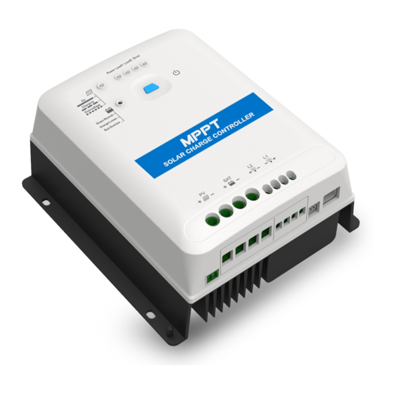
Page 9: Identification Of Parts
1.2 Identification of parts ① ⑨ Power Indicator Load 2 Terminals ② ⑩ Load 1 indicator Grounding terminal ③ ⑪ Load 2 indicator RTS interface ④ ⑫ Error codes PV Terminals Load ON/OFF and setting ⑤ ⑬ Battery Terminals button Load 1/Load 2/Prior Mode ⑥... -
Page 10: Naming Rules
1.3 Naming rules ① For MSC4210N and MSC4215N, the rated voltage of the battery supports 24V only. For other MSC- N types, the rated voltage of the battery supports both 12V and 24V. 1.4 Connection diagram 1.4.1 Battery mode... -
Page 11: Battery Mode
1.4.2 No-battery mode Set the rated voltage level of the battery to auto recognition mode through the below methods; the controller will work in no-battery mode (it also can work in battery mode). In no-battery mode, the PV array will power the load directly. 1) In the [Control Parameter] interface of PC software, select "Self-recognition"... -
Page 12: Interface
2 Interface 2.1 Indicator Indicator Color Status Definition PV connection normal ,but low Green ON solid voltage(low irradiance) from PV, no charging No PV voltage(night time) or PV Green connection fault Slowly Green PV is charging Flashing(1Hz) Fast Flashing PV over voltage (4Hz) Green ON solid... -
Page 13: Button
Fast Flashing Lithium battery low temperature① (4Hz) Controller normal ON solid Battery type: 12V Sealed Green Slowly Battery type: 24V Sealed Flashing Load 1 ON ON solid Battery type: 12V Gel Green Slowly Battery type: 24V Gel Flashing Load 2 ON ON solid Battery type: 12V LFP Green... -
Page 14: Battery Voltage Control Parameters
2.4 Battery voltage control parameters Battery parameters Below values are measured in the 12V/25 º C system; please double the values in the 24V system. Battery type Sealed User Voltage parameters Over Voltage 16.0V 16.0V 9~17V Disconnect Voltage Charging Limit 15.0V 15.0V 9~17V... - Page 15 Limit Voltage; E. Boost Reconnect Charging voltage >Low Voltage Reconnect Voltage. Lithium battery parameters Below values are measured in the 12V/25 º C system; please double the values in the 24V system. Battery type Li(NiCoMn)O2 User Voltage control parameters Over Voltage 15.6V 13.5V...
-
Page 16: Load Output Voltage And Priority Setting
WARNING: The voltage parameters of a lithium battery can be set according to the voltage parameters of lithium battery BMS. WARNING: The required accuracy of BMS shall be no higher than 0.2V. We will not assume any responsibility for the system abnormal when the accuracy of BMS is higher than 0.2 v. -
Page 17: Load Operation Mode
2.6 Load operation mode Working Load Definition modes When the battery voltage reaches the Under Voltage Manual Warning Voltage, the load output will be turned off. Load 1 mode(Default When the battery Voltage reaches the Under Voltage load ON) Warning Reconnect Voltage, the load output will resume. - Page 18 Accessories Included Picture Name Instruction Acquire controller temperature External undertaking temperature compensation of temperature sensor charging and discharging parameters. Plug the external temperature sensor into the port MF58R47K3.81A ❽ of the controller. Optional Picture Name Instruction Acquire battery temperature undertaking temperature compensation of charging and discharging parameters;...
-
Page 19: Installation
3 Installation 3.1 Attentions Be very careful when installing the batteries. Please wear eye protection when installing the open-type lead-acid battery, and rinse with clean water in time for any contact with battery acid. Keep the battery away from any metal objects, which may cause a short circuit of the battery. -
Page 20: Pv Requirements
PV modules and to maximize the conversion of solar energy into electricity. According to the open-circuit voltage (VOC) and the maximum power point voltage (VMPP) of the MPPT controller, the serial connection of PV modules suitable for different controllers can be calculated. The below table is for reference only. - Page 21 (STC (Standard Test Condition):Irradiance 1000W/m2,Module Temperature 25℃,Air Mass1.5.) (2) Max. PV Array Power The MPPT controller has limit current /power function; namely, when the charging current/power exceeds the rated charging current/power, the controller will automatically limit the charging current/power to the rated charging current/power.
-
Page 22: Wire Size
**10N)/150V(MSC **15N) at the lowest environmental temperature, the controller may be damaged. According to the "Peak Sun Hour's diagram," if the power of the PV array exceeds the rated charging power of the controller, the charging time as per the rated power will be prolonged. - Page 23 sum of all PV module's ISC. The ISC of the PV array must not exceed the controller's maximum PV input current. Please refer to the table as below: Max. PV input Model Max. PV wire size* current MSC2210N /10AWG MSC3210N 10mm /8AWG MSC4210N...
-
Page 24: Mounting
24VDC 100W 4.17A 1.5mm /15AWG Load 2 Output Max. output Output power Recommended wire voltage current 12VDC /16AWG 24VDC 1.5A 0.5mm /20AWG 3.4 Mounting WARNING: Risk of explosion! Never install the controller in a sealed enclose with flooded batteries! Do not install the controller in a confined area where battery gas can accumulate. - Page 25 Air outlet Air inlet CAUTION: If the controller is to be installed in an enclosed box, it is important to ensure reliable heat-dissipation through the box. Step 2: Connect wires according to the sequence of ① load 1-- ② load 2-- ③ battery -- ④...
- Page 26 Note: Disconnect the system in the reverse order. Namely, disconnect the system in the order of ④ PV array -- ③ battery -- ② load 2-- ① load 1. CAUTION: When wiring the controller, please do not close the circuit breaker or fuse and make sure that the leads of "+"...
- Page 27 CAUTION: For a common-negative system, such as the RV system, it is recommended to use a common-negative controller. If a common-positive controller is used and the positive electrode is grounded in the common- negative system, the controller may be damaged. Step 4:Connect the remote temperature sensor Connect the remote temperature sensor to interface ⑧...
-
Page 28: Others
4 Others 4.1 Protection Protection Instruction PV limit When the charging current/power of the PV array exceeds Current/limit power the rated charging current/power, the PV array will charge protection the battery as per the rated charging current/power. PV short circuit When not in the PV charging state, the controller will not be protection damaged in the case of a short-circuiting in the PV array. -
Page 29: Troubleshooting
If the load current exceeds 1.05 times the controller's rating current, the controller will cut off the output after 30 seconds delay. In case of overload, the controller is restarted at Overload protection intervals of 5 seconds, 10 seconds, 15 seconds, 20 seconds, 25 seconds, 30 seconds and 1 hour until the power of all the loads is reduced to the rated power. -
Page 30: Maintenance
when sunshine falls on PV array properly Wire connection is Please check the voltage of the correct; the Battery voltage is battery(at least 8V voltage to activate controller is not lower than 8V the controller). working. Check whether the battery voltage is Charging indicator Battery over higher than OVD (over voltage... - Page 31 Make sure no block on airflow around the controller. Clear up any dirt and fragments on the radiator. Check all the naked wires to make sure insulation is not damaged for sun exposure, frictional wear, dryness, insects or rats, etc. Repair or replace some wires if necessary.
-
Page 32: Specifications
8~32V 16~32V voltage range 100V(lowest temperature) 150V(lowest temperature) Max. PV open 92V(At 25℃ operating 138V(At 25℃ operating circuit voltage environment temperature) environment temperature) MPPT voltage (Battery voltage +2V)~ (Battery voltage +2V)~ range 108V Rated charging 260W/12V 390W/12V 1040W/24V power 520W/24V 780W/24V Max. - Page 33 Load adjustment ≤1% rate LINEAR <0.5% adjustment rate Temperature compensate -3mV/℃/2V (Default) coefficient◆ Grounding Type Common negative Communication RS485 port ≤3000 Altitude PV limit current/ limit power/short circuit/reverse /night reverse charging protection Lithium Battery reverse/over voltage/over Protections discharging/over heating/low temperature charging and discharging protection Load short circuit/overload protection, controller over heating protection, against transient...
- Page 34 Load 1 Power reduction curve Load 2 Power reduction curve Mechanical parameters Model MSC2210N MSC3210N MSC4210N MSC4215N 173×158×77. 178×162×80.1 Dimension 213.2×192×96.6mm Mounting 120×149mm 120×153mm 150×182mm dimension Mounting Φ5mm hole size Grounding RNB14-5 terminal Recommend 8AWG 8AWG 6AWG 6AWG ed grounding (10mm (10mm (16mm...
-
Page 35: Annex I Pv Conversion Efficiency Curves
Annex I PV Conversion Efficiency Curves Test condition: Illumination Intensity: 1000W/m Temperature: 25℃ Model: MSC2210N 1. PV array Max. power point voltage(17V, 34V)/system voltage(12V) 2. PV array Max. power point voltage(34V, 51V, 68V)/system voltage(24V) - Page 36 Model: MSC3210N 1. PV array Max. power point voltage(17V, 34V)/system voltage(12V) 2. PV array Max. power point voltage(34V, 51V, 68V)/system voltage(24V)
- Page 37 Model: MSC4210N PV array Max. power point voltage(34V, 51V, 68V)/system voltage(24V) Model MSC4215N PV array Max. power point voltage(34V, 68V, 102V)/system voltage(24V)
-
Page 38: Annex 2 Load Conversion Efficiency Curves
Annex 2 Load Conversion Efficiency Curves Load 1 12V load output conversion efficiency 100.0% 98.0% 96.0% 94.0% 92.0% 90.0% 88.0% 86.0% 84.0% 82.0% 80.0% Output power BAT12V BAT24V Load 1 24V load output conversion efficiency 100.0% 98.0% 96.0% 94.0% 92.0% 90.0% 88.0% 86.0%... - Page 39 Load 2 12V load output conversion efficiency 100.0% 97.0% 94.0% 91.0% 88.0% 85.0% 82.0% 79.0% 76.0% 73.0% 70.0% Output power BAT12V BAT24V Load 2 24V load output conversion efficiency 100.0% 97.0% 94.0% 91.0% 88.0% 85.0% 82.0% 79.0% 76.0% 73.0% 70.0% Output power BAT12V BAT24V...
- Page 40 HUIZHOU EPEVER TECHNOLOGY CO., LTD. Beijing Tel: 010-82894896/82894112 Huizhou Tel: 0752-3889706 E-mail: webmaster@epsolarpv.com www.epsolarpv.com.cn Website: www.epever.com.cn...
Need help?
Do you have a question about the MPPT and is the answer not in the manual?
Questions and answers
Model TRIRON2210N. No current out from the load terminal, and no light at all on the load indicator. None of the tried load modes (101,102..,201...) appear to change that. What to do with the brand new charge controller?