
Subscribe to Our Youtube Channel
Related Manuals for National Flooring Equipment 3535


Summary of Contents for National Flooring Equipment 3535
- Page 1 Read manual before operating machine Instruction Manual 800.245.0267 • 763.535.8206 • Fax: 800.648.7124 nationalequipment.com 402564 Rev A...
-
Page 2: Table Of Contents
■ Table of Contents....................■ Rules for Safe Operation..................Grounding..................Extension Cords................. ■ Introduction......................■ Accessories......................■ Diamonds......................■ Maintenance ....................10-11 ■ Complete Parts List ..................■ Part Numbers and Diagrams................■ Labels ......................■ Guarantee......................■ Return Sheet .................... -
Page 3: Rules For Safe Operation
RULES FOR SAFE OPERATION READ AND SAVE ALL INSTRUCTIONS FOR FUTURE USE. Before use, be sure everyone operatingthis equipment reads and understands this manual as well as any labels packaged with or attached to the machine and components and view the instruction video. Extra copies of the manual and video are available upon request. - Page 4 RULES FOR SAFE OPERATION KEEP HANDS AWAY FROM ALL MOVING PARTS. DO NOT ABUSE CORD: Never unplug by yanking the cord from the outlet. Pull plug rather than cord to reduce the risk of damage. Keep the cord away from heat, oil, sharp objects, cutting edges and moving parts.
-
Page 5: Grounding
RULES FOR SAFE OPERATION GROUNDING WARNING: Improperly connecting the grounding wire can result in the risk of electric shock. check with a qualified electrician if you are in doubt as to whether the outlet is properly grounded. Do not modify the plug provided with the tool. Never remove the grounding prong from the plug. Do not use the tool if the cord or plug is damaged. -
Page 6: Extension Cords
RULES FOR SAFE OPERATION EXTENSION CORDS WARNING: Electrical cords can be hazardous. Misuse can result in fire or death by electrical shock. Read carefully and follow all directions. Grounded tools require a three wire extension cord. Double insulated tools can use either a two or three wire extension cord. -
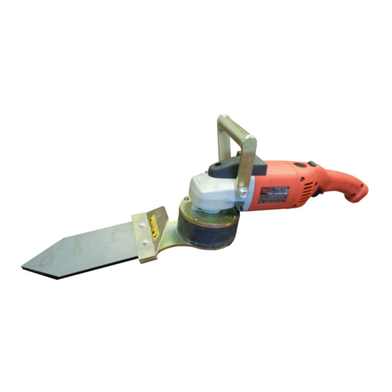
Page 7: Introduction
INTRODUCTION BREAKING IN the #3535 CORNER TOOL • After the first half hour (30 min.) of use, check all screws and fittings for a tight and secure fit. - Page 8 Due to our lack of control of the many flooring removal conditions and techniques used in the field, National will not be held responsible for injury to anyone or damage to any object, resulting through use of the 3535 Corner Tool regardless of its age or condition or the manner in which it is used.
- Page 9 MAINTENANCE INNER PARTS ASSEMBLY/DISASSEMBLY Step 1) Remove four (4) lower cutting head bolts with a 7/16" wrench. Step 2) Remove four (4) bottom head bolts with a 7/16" wrench. This will remove the rubber ring. Step 3) Remove eccentric bearings by pulling off with with a bearing puller (See Figure 1).
-
Page 10: Accessories
ACCESSORIES 400016 400026 400013 400015 400014 400012 400012 Tooling Attachment, Round 5” 400013 Tooling Attachment, Triangle 5” 400014 Tooling Attachment, Round 10“ 400015 Tooling Attachment, Triangle 10” 400016 Tooling Attachment, Post Tool (Left) 400026 Tooling Attachment, Post Tool (Right) -
Page 11: Diamonds
DIAMONDS Corner Resin Corner Brazed 9435-50 Grit 9420-30 30 Grit 9435-100 Grit 9420-50 50 Grit 9435-200 Grit 9420-100 100 Grit 9435-400 Grit 9435-800 Grit 9435-1500 Grit 9435-3000 Grit Polishing Pads Brazed Diamond 9267-50 50 Grit 9267-100 100 Grit 9235-16 16 Grit 9267-200 200 Grit 9235-30... - Page 12 PARTS LIST PART # DESCRIPTION 6300-1 Base Plate 6300-2 Rubber Ring 6300-3 Bearing Cup 6300-4 Cutting Head 6300-5 Blade Mount 6300-57 Eccentric 71231 Bearing 25MM ID (2) 73006 1/4-20 x 3/4 button head cap screw (4) (not shown) 73014 1/4-20 x 1/2 hexhead Bolt 73019 1/4-20 x 3/4 hexhead bolt (8) (Not Shown) 73240...
-
Page 13: Part Numbers And Diagrams
PART NUMBERS AND DIAGRAMS 6300-5 6300-57 6300-1 6300-4 6300-2 71231... -
Page 14: Return Sheet
RETURN SHEET Company Name: Contact Name: Telephone Number: Approximate Usage (hours): Problems Encountered: Check One: Repair Do you wish to be contacted before repairing Return Contact National if a loaner is needed Return Authorization Number Date required, contact National Customer Number if known...
Need help?
Do you have a question about the 3535 and is the answer not in the manual?
Questions and answers