Table of Contents
Advertisement
ユーザーマニュアル
사용�설명서
用户手册
用戶手冊
MANUALE
MANUEL DE
INSTRUKCJA
MANUAL
BRUKERMANUAL
KULLANMA
MANUAL
USER
UŽIVATELSKÝ
ANVÄNDARMANUAL
KÄYTTÄJÄN
POUŽÍVATEĽSKÁ
BENUTZERHANDBUCH
BRUGERVEJLEDNING
GEBRUIKERSHANDLEIDING
MANUAL
UTENTE
DE USUARIO
KILAVUZU
L'UTILISATEUR
UŻYTKOWNIKA
DO USUÁRIO
KÄSIKIRJA
MANUÁL
PRÍRUČKA
IntelliDoX™
Docking Module
便携式多种气体检测仪
便攜式多氣體檢測儀
휴대용�다중�가스�감지기
ポータブルマルチガス検知器
Detector múltiplo de gás portátil
Bärbar detektor med flera gaser
Taşınabilir çoklu gaz dedektörü
Bærbar flere gassdetektorer
Prenosný viacnásobný detektor plynov
Bærbar flere gasdetektorer
Kannettava useita kaasunilmaisimia
Draagbare meervoudige gasdetector
Detector de gases múltiples portátil
Přenosný vícenásobný detektor plynu
Przenośny detektor wielu gazów
Rilevatore di gas multiplo portatile
Détecteur de gaz multiple portable
Tragbarer Mehrfachgasdetektor
M05-4002-003 ZH-TW-Rev.A
M05-4002-003 ZH-CN-Rev.A
M05-4002-003 NO-Rev.A
M05-4002-003 RU-Rev.A
M05-4002-003 KO-Rev.A
M05-4002-003 DA-Rev.A
M05-4002-003 DE-Rev.A
M05-4002-003 NL-Rev.A
M05-4002-003 CZ-Rev.A
M05-4002-003 PL-Rev.A
M05-4002-003 TR-Rev.A
M05-4002-003 AR-Rev.A
M05-4002-003 PT-Rev.A
M05-4002-003 SV-Rev.A
M05-4002-003 SK-Rev.A
M05-4002-003 ES-Rev.A
M05-4002-003 FR-Rev.A
M05-4002-003 JA-Rev.A
M05-4002-003 FI-Rev.A
M05-4002-003 IT-Rev.A
Advertisement
Table of Contents

Related Manuals for Honeywell IntelliDoX


Summary of Contents for Honeywell IntelliDoX
- Page 1 GEBRUIKERSHANDLEIDING MANUAL L'UTILISATEUR UTENTE DE USUARIO KILAVUZU UŻYTKOWNIKA DO USUÁRIO KÄSIKIRJA MANUÁL PRÍRUČKA IntelliDoX™ Docking Module 便攜式多氣體檢測儀 便携式多种气体检测仪 ポータブルマルチガス検知器 휴대용�다중�가스�감지기 Tragbarer Mehrfachgasdetektor Détecteur de gaz multiple portable Rilevatore di gas multiplo portatile Przenośny detektor wielu gazów Přenosný vícenásobný detektor plynu Draagbare meervoudige gasdetector Detector de gases múltiples portátil...
-
Page 2: Table Of Contents
Protect Module Operations with a Passcode ................... 62 Adjust Time and Date Settings ......................63 Configure the IntelliDox and the device via Safety Suite..............64 Configure Module and Detector Settings via Safety Suite Device Configurator ....... 66 Hibernation ..............................73 Configure Hibernation ........................ - Page 3 Update Module Firmware ......................... 84 Update Detector Firmware ....................... 88 Replace Detector Cradle and Calibration Insert ..................91 Upgrade the IntelliDoX to Fit Compatible Detectors ................ 92 Replace the Detector Cradle ......................93 Replace the Calibration Insert ......................95 Maintenance ..............................97 Clean and Maintain the Module .......................
-
Page 4: About This Publication
In no event is Honeywell liable to anyone for any indirect, special or consequential damages. The information and specifications in this document are subject to change without notice. -
Page 5: Important Safety Information: Read First
This IntelliDoX module is intended for use as a stand-alone docking module, or as a component Do not use calibration gas cylinders past their in a connected group of up to five IntelliDoX expiration date. -
Page 6: Getting Started
INTELLIDOX DOCKING MODULE USER MANUAL || GETTING STARTED Getting Started This section contains information and illustrations related to the module and its components. It also includes an overview of the module settings menu and general instructions for inserting a detector and using the detector operations menu on the module. -
Page 7: About The Intellidox Docking Module
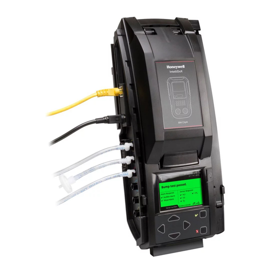
USER MANUAL || GETTING STARTED About the IntelliDoX Docking Module The IntelliDoX Docking Module (‘the module’) is an automatic test and calibration station for use with portable gas detectors manufactured by Honeywell. The module automatically performs essential procedures including sensor identification, bump tests, calibrations, alarm tests and data transfers. -
Page 8: What's In The Box
If the module is damaged or if parts are missing, contact Honeywell or an authorized distributor immediately. IntelliDoX Enabler Kit You need one IntelliDoX Enabler Kit for each stand-alone IntelliDoX module or group of up to 5 connected modules. Each Enabler Kit contains: One power supply and AC power cord appropriate to shipping destination;... -
Page 9: Intellidox At A Glance
INTELLIDOX DOCKING MODULE USER MANUAL || GETTING STARTED IntelliDoX at a Glance HONEYWELL PAGE 8 OF 119... -
Page 10: Inlet Keys
When the single-inlet key is inserted into a module, gas inlet 1 is active and gas inlets 2, 3 and 4 are inactive. Gas Cylinder with a Single-Inlet Key When you connect a gas cylinder to IntelliDoX with a single-inlet key, you will see one connected gas type on the LCD screen: Single-inlet key: IntelliDoX... - Page 11 Multi-inlet key comes standard with IDX-Ultra to support BW Ultra 5 gas detector. Connected Gas Cylinders with a Multi-Inlet Key When you connect multiple gas cylinders to IntelliDoX with a multi-inlet key, you will see multiple connected gas types on the LCD screen:...
-
Page 12: Lcd Screen
INTELLIDOX DOCKING MODULE USER MANUAL || GETTING STARTED LCD Screen Screen Color HONEYWELL PAGE 11 OF 119... -
Page 13: Keypad
INTELLIDOX DOCKING MODULE USER MANUAL || GETTING STARTED Keypad Keypad Buttons Scroll right Scroll left Scroll up Scroll down Press and hold until the module settings menu is displayed. Press and release to select a menu item or save changes. -
Page 14: Assemble Modules
INTELLIDOX DOCKING MODULE USER MANUAL || ASSEMBLE MODULES Assemble Modules This section contains work plans and instructions for assembling and installing individual modules and groups of up to five modules. HONEYWELL PAGE 13 OF 119... -
Page 15: Work Plan: Assemble Individual Modules
INTELLIDOX DOCKING MODULE USER MANUAL || ASSEMBLE MODULES Work Plan: Assemble Individual Modules Follow these steps to assemble and prepare an individual module for first-time use: Place the module and component parts on a clean, dry work surface. Verify that the appropriate inlet key is inserted. Replace the inlet key if necessary. For more information, see Inlet Keys Assemble the stand, or mount the module on a wall or DIN rail. -
Page 16: Work Plan: Assemble Groups Of Up To Five Connected Modules
INTELLIDOX DOCKING MODULE USER MANUAL || ASSEMBLE MODULES Work Plan: Assemble Groups of up to Five Connected Modules Up to five modules may be connected to form a group. Connected modules share the power supply, exhaust tubing, inlet filter, connected test gas cylinders and network connection. Follow these steps to assemble and prepare groups of up to five connected modules for first use: Place the modules and component parts on a clean, dry work surface. -
Page 17: Assemble The Stand
Do not use the stand if parts are missing or damaged. Do not attempt to repair or replace any parts of the stand. If the plate is damaged or missing, contact Honeywell or an authorized distributor. -
Page 18: Connect Modules
INTELLIDOX DOCKING MODULE USER MANUAL || ASSEMBLE MODULES Connect Modules Up to 5 modules may be connected to form a group. Connected modules share a power supply, network connection, exhaust tubing, inlet filter assemblies, and connected calibration gas cylinders. Connecting Modules Assemble the stand for each module you plan to connect. -
Page 19: Mount On A Wall
You can use the back panel to mount the module securely to a wall. Because wall materials vary, mounting hardware is not provided. Honeywell strongly recommends that wall-mounting is performed by a qualified installation contractor. Sufficient expertise is required to: Determine the strength of the wall supporting the module;... - Page 20 INTELLIDOX DOCKING MODULE USER MANUAL || ASSEMBLE MODULES Mounting Individual Modules on a Wall Prepare the modules for mounting. Disconnect modules that are connected into groups. Disconnect the power cord, network cable, tubing and inlet filter assemblies. Remove the end plate.
- Page 21 INTELLIDOX DOCKING MODULE USER MANUAL || ASSEMBLE MODULES Mounting Connected Modules on a Wall Prepare the modules for mounting. Disconnect modules that are connected into groups. Disconnect the power cord, network cable, tubing and inlet filter assemblies. Remove the end plate.
- Page 22 For best results, Honeywell recommends that you hold the remainder of the group firmly in position while pushing to help protect the remaining modules in the group from excessive movement or falls.
-
Page 23: Mount On Parallel Din Rails
Space the DIN rails 15.2 centimeters (6 inches) apart on center. Honeywell strongly recommends using a DIN rail end plate when mounting in a vehicle, or when lateral motion is possible, or when attaching the first module in a grouped system. If a DIN rail end plate is not available, use the anchor holes in the back panel to secure the module to the wall. - Page 24 INTELLIDOX DOCKING MODULE USER MANUAL || ASSEMBLE MODULES Mounting Modules on Parallel DIN Rails Prepare the modules for mounting. Disconnect modules that are connected into groups. Disconnect the power cord, network cable, tubing and inlet filter assemblies. Remove the end plate.
- Page 25 INTELLIDOX DOCKING MODULE USER MANUAL || ASSEMBLE MODULES Removing an Individual Module from Parallel DIN Rails Disconnect the power cord, network cable, tubing and inlet filter assemblies. Remove the end plate. Find the DIN mount lock on the lower right side of the module.
-
Page 26: Prepare Modules For Use
INTELLIDOX DOCKING MODULE USER MANUAL || PREPARE MODULES FOR USE Prepare Modules for Use This section contains instructions and information related to preparing modules for use. HONEYWELL PAGE 25 OF 119... -
Page 27: Attach The End Plate
INTELLIDOX DOCKING MODULE USER MANUAL || PREPARE MODULES FOR USE Attach the End Plate The end plate must be attached and locked with the latch arm before connecting power supply or connecting gas cylinders. The end plate must remain securely latched at all times during operation. -
Page 28: Connect The Exhaust Tubing
USER MANUAL || PREPARE MODULES FOR USE Connect the Exhaust Tubing Each IntelliDoX Enabler Kit includes tubing that may be cut to a length that is appropriate for the exhaust inlet. The maximum recommended exhaust tubing length is 15 meters (49.5 feet). -
Page 29: Connect The Inlet Filter
USER MANUAL || PREPARE MODULES FOR USE Connect the Inlet filter Each IntelliDoX Enabler Kit contains inlet filters. Unless otherwise specified, the purge inlet is configured to use ambient air in a fresh air environment with a normal atmosphere of 20.9% v/v O that is free of hazardous gas. -
Page 30: Insert The Inlet Plugs
USER MANUAL || PREPARE MODULES FOR USE Insert the Inlet Plugs Each IntelliDoX Enabler Kit contains inlet plugs. Verify that an inlet plug is inserted into each unused gas inlet before using the module. Once inserted, the inlet plugs help to protect the module from dust ingress. -
Page 31: Connect The Power
USER MANUAL || PREPARE MODULES FOR USE Connect the Power Each IntelliDoX Enabler Kit contains one power supply and AC power cord. Use only the power supply provided in the Enabler Kit to connect the module to an appropriate electrical power outlet. -
Page 32: Connect The Module To A Network
Network Passcode To prevent product tampering on IntelliDoX there is now a Network Passcode menu. To be granted access to this menu, the user needs to first enter the Module Passcode. This UI password requirement is designed to stop unauthorized access to view or change the Network Passcode. - Page 33 For newer Safety Suite Device Configurator versions, Safety Suite Device Configurator will require entering the Network Passcode in order to add IntelliDoX. This will be a one time only process. Safety Suite Device Configurator will need to send the IntelliDoX the network passcode to verify the connection.
- Page 34 Default User Name and Password for Internet Browser Access The user name and password are case sensitive. Honeywell recommends that you change the password for each networked module. The default user name is admin.
- Page 35 In the Add IntelliDoX for manual detection field, enter the IP address of the IntelliDoX, and then click SAVE. Wait until Progress bar is refreshed. Click the Devices Tab, and then verify that the IntelliDoX is added in the list of devices. HONEYWELL...
- Page 36 The IntelliDoX Enabler Kit includes tubing and quick connect fittings that are appropriate for use with calibration gas cylinders that are approved for use with this product. For best results, Honeywell recommends that the tubing is between 39 inches (1 meter) and 33 feet (10 meters) in length for calibration gas cylinders.
- Page 37 3/16 inch (9.5 millimeter) I.D. tubing to the demand flow regulator. Cut 1/8 inch (3.2 millimeter) I.D. tubing to an appropriate length. Honeywell recommends that the tubing is between 39 inches (1 meter) and 33 feet (10 meters) in length.
-
Page 38: Dock Station Settings Menu
INTELLIDOX DOCKING MODULE USER MANUAL || DOCK STATION SETTINGS MENU Dock Station Settings Menu This section contains information and instructions for using the Dock Station Settings menu. HONEYWELL PAGE 37 OF 119... -
Page 39: Display The Adjust Dock Station Settings Menu
INTELLIDOX DOCKING MODULE USER MANUAL || DOCK STATION SETTINGS MENU Display the Adjust Dock Station Settings Menu Display the Adjust dock station settings menu when you want to: Adjust the brightness of the LCD screen; Change date and time settings for the module;... -
Page 40: Adjust The Lcd Brightness
INTELLIDOX DOCKING MODULE USER MANUAL || DOCK STATION SETTINGS MENU Adjust the LCD Brightness When you adjust and save the settings for one module in a group, the settings for all of the modules in the group are also changed. -
Page 41: Adjust Date And Time Settings
INTELLIDOX DOCKING MODULE USER MANUAL || DOCK STATION SETTINGS MENU Adjust Date and Time Settings Follow these instructions when you want to adjust the module time and date settings manually via the Adjust dock station settings menu. When you adjust and save the settings for one module in a group, the settings for all of the modules in the group are also changed. -
Page 42: Configure Gas Inlets
INTELLIDOX DOCKING MODULE USER MANUAL || DOCK STATION SETTINGS MENU Configure Gas Inlets For each attached calibration gas cylinder, you must configure the gas blend, and then configure each gas type and concentration contained in the gas blend. You may also record the lot number of the calibration gas cylinder. - Page 43 INTELLIDOX DOCKING MODULE USER MANUAL || DOCK STATION SETTINGS MENU Configure the gas type for the blend. To configure a gas type in a multi-gas blend, select Gas blend from the Inlet edit menu, and then press to select one of the gases available in the blend.
-
Page 44: Display The Select Language Menu
INTELLIDOX DOCKING MODULE USER MANUAL || DOCK STATION SETTINGS MENU Display the Select Language Menu Use the Select Language menu to change the docking station's display language. You can select English, French, German, Spanish, or Portuguese. Adjust dock station settings... -
Page 45: Display The About Summary Screen
INTELLIDOX DOCKING MODULE USER MANUAL || DOCK STATION SETTINGS MENU Display the About Summary Screen The About information screen displays summary information about the module that may be helpful when you install or configure modules, such as: Module serial number;... -
Page 46: Detector Operations
INTELLIDOX DOCKING MODULE USER MANUAL || DETECTOR OPERATIONS Detector Operations This section contains information and instructions for inserting a detector and performing certain operations. HONEYWELL PAGE 45 OF 119... -
Page 47: Insert A Detector
INTELLIDOX DOCKING MODULE USER MANUAL || DETECTOR OPERATIONS Insert a Detector Verify that the detector is compatible with the module. The detector model must match the model displayed on the module lid. Activate the detector if necessary. If you plan to perform compliance tests, then activate the detector and verify it is in normal operating mode prior to insertion. -
Page 48: Detector Operations Menu
INTELLIDOX DOCKING MODULE USER MANUAL || DETECTOR OPERATIONS Detector Operations Menu After the detector is recognized and automated procedures are completed, the detector operations menu and What do you need to do? are displayed. Press on the module keypad to select a menu item, and then follow on-screen instructions to perform the selected procedure. -
Page 49: Bump Test
LCD. It is recommended using the following regulator models: REG-DF-1, REG-DF-2, or REG-DF-3. These can all be found in the price list catalog provided by Honeywell. A bump test is a procedure that confirms a detector’s ability to respond to target gases by exposing the detector to a known gas concentration. - Page 50 Do not operate the module in a hazardous area. Failure to adhere to this guideline can result in possible personal injury and/or property damage. The use of gas cylinders other than those specified by Honeywell may result in unsafe bump tests or possible non-recoverable failure of the equipment, and will invalidate the warranty.
- Page 51 When Pre-Conditioning of the system is required please follow the procedure described below: In an IntelliDoX the only means of flowing the gas is with a bump test or calibration. To bump test Ultra for CL2/NH3 in an IntelliDoX place unit in the dock, and then Select bump test using the IntelliDoX menu.
-
Page 52: Fastbump
INTELLIDOX DOCKING MODULE USER MANUAL || DETECTOR OPERATIONS FastBump When IntelliDoX is set to FastBump, you see at the top right of the LCD screen. FastBump is an accelerated compliance test that confirms a detector’s ability to respond to target gases by exposing the detector to a known gas concentration. When a compatible detector is inserted into the configured module, FastBump and event log transfers begin automatically after the detector is recognized. - Page 53 INTELLIDOX DOCKING MODULE USER MANUAL || DETECTOR OPERATIONS Standard Bump Testing During a standard bump test, the bump procedure and other procedures configured to occur automatically on insertion are performed. You must use instrument management software to configure the module to automatically bump test a compatible detector on insertion.
-
Page 54: Calibration
IntelliDox will show an alarm in the LCD. It is recommended using the following regulator models: REG-DF-1, REG-DF-2, or REG-DF-3. These can all be found in the price list catalog provided by Honeywell. Calibration is a two-step procedure that determines the measurement scale for the detector’s response to gas. - Page 55 Do not operate the module in a hazardous area. Failure to adhere to this guideline can result in possible personal injury and/or property damage. The use of calibration gas cylinders other than those specified by Honeywell may result in unsafe calibration or possible non-recoverable failure of the equipment, and will invalidate the warranty.
- Page 56 PID under BW Ultra configuration tab and save this configuration on Ultra detector. Install multi inlet key in the IntelliDoX and configure 2 inlets for Isobutylene gas in which one inlet is for span low gas concentration and another is for span high gas concentration.
- Page 57 INTELLIDOX DOCKING MODULE USER MANUAL || DETECTOR OPERATIONS Special Considerations for IntelliDoX BW Icon (DX-CP) Note: The external filter on BW Icon is supported while docked into IDX BW Icon (DX-CP) and does not need to be removed. If the detector fails calibration, check for and replace a dirty filter, then calibrate again.
- Page 58 USER MANUAL || DETECTOR OPERATIONS Ensuring proper operation of the IntelliDoX BW Clip4 module After performing a bump test or calibration, remove the detector from the IntelliDoX docking module to allow any residual gas to clear. Leaving the detector in the docking module may cause it to fail the calibration. If a detector is bump tested and then a calibration is performed without removing it from the docking module, residual gas may cause the calibration to fail.
-
Page 59: Transfer Datalogs From A Detector
INTELLIDOX DOCKING MODULE USER MANUAL || DETECTOR OPERATIONS Transfer Datalogs from a Detector There are two ways to transfer data logs from a detector to the module: Manually, via the module operations menu, or Automatically, by configuring detector settings via Safety Suite Device Configurator or Safety Suite. -
Page 60: Display The Adjust Dock Station Settings Menu
INTELLIDOX DOCKING MODULE USER MANUAL || DETECTOR OPERATIONS Display the Adjust Dock Station Settings Menu Insert a compatible detector into the module. Detector identification is displayed on the LCD. After the detector is recognized, procedures specified to occur automatically on insertion are performed. -
Page 61: Charge A Detector
INTELLIDOX DOCKING MODULE USER MANUAL || DETECTOR OPERATIONS Charge a Detector You may use the module to charge compatible detectors that are fitted with rechargeable batteries. For more information on battery maintenance, refer to the appropriate detector operator manual. Charge only in a normal environment that is 20.9% v/v O and free of hazardous gas. -
Page 62: Configure Settings Via Safety Suite Device Configurator And Safety Suite Software
INTELLIDOX DOCKING MODULE USER MANUAL || CONFIGURE SETTINGS VIA SAFETY SUITE DEVICE CONFIGURATOR AND SAFETY SUITE SOFTWARE Configure Settings via Safety Suite Device Configurator and Safety Suite Software This section contains general instructions for creating and transferring configuration files to modules and detectors via Safety Suite Device... -
Page 63: Protect Module Operations With A Passcode
Select the tab for a compatible detector, and then select the IntelliDoX Configuration tab for the compatible detector. In the IntelliDoX Operations section, select the operations you want to protect with a passcode. In the IntelliDoX Passcode section, click to select a 4-digit number. -
Page 64: Adjust Time And Date Settings
• Configure compatible detectors to synchronize time and date settings to the module after inserting the device. From the main window, click IntelliDoX Configuration. From the IntelliDoX Configuration panel, click DATE & TIME, and then select SYNCHRONIZE WITH SERVER. A Date and time sync successfully message is displayed. -
Page 65: Configure The Intellidox And The Device Via Safety Suite
USER MANUAL || CONFIGURE SETTINGS VIA SAFETY SUITE DEVICE CONFIGURATOR AND SAFETY SUITE SOFTWARE Configure the IntelliDox and the device via Safety Suite From the ACTIONS column, expand ACTIONS and select Device Details to download device’s datalog and event logs. The Safety Suite Device Configurator will retrieve the configuration from the IntelliDoX. - Page 66 INTELLIDOX DOCKING MODULE USER MANUAL || CONFIGURE SETTINGS VIA SAFETY SUITE DEVICE CONFIGURATOR AND SAFETY SUITE SOFTWARE Go to the Settings section. And adjust the device configuration. Click SAVE. The Safety Suite Device Configurator will display whether the configuration is successfully saved or not.
-
Page 67: Configure Module And Detector Settings Via Safety Suite Device Configurator
INTELLIDOX DOCKING MODULE USER MANUAL || CONFIGURE SETTINGS VIA SAFETY SUITE DEVICE CONFIGURATOR AND SAFETY SUITE SOFTWARE Configure Module and Detector Settings via Safety Suite Device Configurator Certain features, options and settings for the module and/or compatible detectors can be configured through Safety Suite Device Configurator software. - Page 68 Select Configure Devices via IntelliDoX on the Devices menu. The IntelliDoX Configuration Selection dialog box is displayed. Select a configuration file and click OK. The IntelliDoX Device Configuration dialog box is displayed Select the tab for a compatible detector, and then select the detector configuration tab.
- Page 69 Configurator Create the configuration file. See Configure Module and Detector Settings. Click Save to IntelliDoX. The IntelliDoX Selection dialog box is displayed. Select one or more modules, and then click OK to transfer the configuration file to the selected modules.
- Page 70 Note: during update through USB two messages can be shown “Communication Failure” and/or “Configuration Corrupt”. These messages may appear only while the IntelliDoX is in a gang arrangement. If one IntelliDoX in this arrangement displays the warning message “CONFIGURATION CORRUPT SETTINGS LOADED FROM FILE” it is likely that another IntelliDoX will show the “MULTI-DOCK COMMUNICATION...
- Page 71 Configurator software is installed. If the date is incorrect, change the date on the PC. If the time is incorrect, click on the Time zone selector to select a different time zone. When the correct date and time are displayed, click Set IntelliDoX Time. The IntelliDoX Time Confirmation dialog box is displayed.
- Page 72 Open the Safety Suite Device Configurator software, and then log in with your username and password. Click the Devices tab, and verify the IntelliDoX you want to communicate with is added and visible. From the ACTIONS column, expand ACTIONS and select Device Details. The IntelliDoX Configuration panel is displayed.
- Page 73 INTELLIDOX DOCKING MODULE USER MANUAL || CONFIGURE SETTINGS VIA SAFETY SUITE DEVICE CONFIGURATOR AND SAFETY SUITE SOFTWARE Under Timezone Settings, select Automatically adjust clock for Daylight Savings Time. Click the Time zone selector and then select a time zone from the drop down menu.
-
Page 74: Hibernation
Hibernation Hibernation is a factory-installed feature that is available for certain detectors manufactured by Honeywell. When hibernation is activated, all detector safety functions are disabled and the detector operating life countdown is suspended. Hibernation may extend the service life of the detector, limited by the specified maximum operating life of the detector. -
Page 75: Configure Hibernation
INTELLIDOX DOCKING MODULE USER MANUAL || HIBERNATION Configure Hibernation You must use Safety Suite Device Configurator or Safety Suite software to create a configuration file to activate hibernation on insertion. After the configuration file is created, you can use Safety Suite Device Configurator or Safety Suite software, or a USB flash drive to transfer the file to one or more modules. - Page 76 Select Configure Devices via IntelliDoX on the Devices menu. The IntelliDoX Configuration Selection dialog box is displayed. Select a configuration file and click OK. The IntelliDoX Device Configuration dialog box is displayed. Select the tab for a compatible detector that supports hibernation, and then select the IntelliDoX Configuration tab.
-
Page 77: Creating A Hibernation Configuration File Via Safety Suite Software
INTELLIDOX DOCKING MODULE USER MANUAL || HIBERNATION Creating a Hibernation Configuration File via Safety Suite Software From the main window, click IntelliDox Configuration. From the IntelliDoX Configuration panel, select the Hibernation checkbox. Click Save. HONEYWELL PAGE 76 OF 119... - Page 78 Safety Suite Device Configurator Software Create the hibernation configuration file. See Hibernation. Click Save to IntelliDoX. The IntelliDoX Selection dialog box is displayed. Select one or more modules, and then click OK to transfer the hibernation configuration file to the selected modules.
- Page 79 INTELLIDOX DOCKING MODULE USER MANUAL || HIBERNATION Activating Detector Hibernation Verify that the module is configured for hibernation. The LCD is gray. The hibernation symbol is displayed. Insert a compatible detector into the module. Detector identification is displayed on the LCD.
-
Page 80: Transfer Data Files
INTELLIDOX DOCKING MODULE USER MANUAL || TRANSFER DATA FILES Transfer Data Files This section contains information and instructions related to transferring data files from detectors to modules and from modules to a PC via Safety Suite Device Configurator, Safety Suite or USB flash drive. -
Page 81: Transfer Data Files From The Module
Start Safety Suite Device Configurator software, and then log in as an administrator. Select Import from the Devices menu. The Import Device Data window is displayed. Select IntelliDoX Import. The Getting list of IntelliDoXs message box may be displayed while Safety Suite Device Configurator prepares a list of available modules. - Page 82 After the module information is gathered, the Scheduled Import dialog box is displayed. Select one or more modules from the Available IntelliDoX list, and then click Add to Schedule. The selected modules are added to the Scheduled IntelliDoX list. Set the date, time and occurrence options under Next Scheduled For.
- Page 83 INTELLIDOX DOCKING MODULE USER MANUAL || TRANSFER DATA FILES Transferring Data Files Manually via USB Flash Drive For connected modules, you must transfer the data files from each module in the group. Insert the USB flash drive into the USB port on the module. The USB File Copy Utility menu is displayed.
-
Page 84: Update Firmware
Update Firmware Honeywell is committed to continuously improving product features and performance. Thus, firmware updates may become available for certain products. Honeywell recommends that you visit the appropriate product site www.honeywellanalytics.com to find and download the latest firmware version for your products. -
Page 85: Update Module Firmware
INTELLIDOX DOCKING MODULE USER MANUAL || UPDATE FIRMWARE Update Module Firmware Honeywell is committed to continuously improving product features and performance. As a result, firmware updates may become available for the modules. Honeywell recommends that you visit the appropriate product site at https://www.honeywellanalytics.com/en/products/IntelliDoX... - Page 86 INTELLIDOX DOCKING MODULE USER MANUAL || UPDATE FIRMWARE Press and hold on the keypad until Adjust dock station settings is displayed on the LCD. Press to select About, and then press . The About this docking module summary screen is displayed.
- Page 87 Download and save the firmware update file to a PC or network drive. Do not rename the file. Start Safety Suite Device Configurator software, and then log in as an administrator. Select Configure Devices via IntelliDoX on the Devices menu. The IntelliDoX Configuration Selection dialog box is displayed. HONEYWELL...
- Page 88 Select the downloaded file, and then click Open. The IntelliDoX Selection dialog box is displayed. Select one or more IntelliDoX modules, and then click OK. A progress screen is displayed while the firmware update file is automatically transferred to the selected modules.
-
Page 89: Update Detector Firmware
INTELLIDOX DOCKING MODULE USER MANUAL || UPDATE FIRMWARE Update Detector Firmware Honeywell is committed to continuously improving product features and performance. As a result, firmware updates for detectors may become periodically available. Honeywell recommends that you visit the appropriate product site at https://www.honeywellanalytics.com/en/products/IntelliDoX... - Page 90 Select the downloaded file, and then click Open. The IntelliDoX Selection dialog box is displayed. Select one or more IntelliDoX modules, and then click OK. A progress screen is displayed while the firmware update file is automatically transferred to the selected modules.
- Page 91 Updating the Detector Firmware via Safety Suite When a new Firmware version is available, the user will get an UPDATE button under the FIRM VERSION section in the IntelliDoX Configuration panel. Click UPDATE; Safety Suite will automatically select the file stored in the database and proceed with the firmware upgrade.
-
Page 92: Replace Detector Cradle And Calibration Insert
INTELLIDOX DOCKING MODULE USER MANUAL || REPLACE DETECTOR CRADLE AND CALIBRATION INSERT Replace Detector Cradle and Calibration Insert This section contains information and instructions related to replacing an IntelliDoX detector cradle and calibration insert. HONEYWELL PAGE 91 OF 119... -
Page 93: Upgrade The Intellidox To Fit Compatible Detectors
CRADLE AND CALIBRATION INSERT Upgrade the IntelliDoX to Fit Compatible Detectors The IntelliDoX system is designed for users to upgrade their detector docking solution to meet their changing needs. The IntelliDoX allows users to upgrade from one detector to another with the replacement of the detector cradle and calibration insert. -
Page 94: Replace The Detector Cradle
CRADLE AND CALIBRATION INSERT Replace the Detector Cradle To replace the cradle, remove the cradle from the IntelliDoX (unscrew the screws and unplug the connector), and then install the replacement cradle. Disconnect the power cord, network cable, tubing, and inlet filter assemblies from the IntelliDoX. - Page 95 Get the replacement cradle. Plug the replacement cradle's connector cable into the circuit board. Slide the replacement cradle's tabs under the IntelliDoX top assembly to place the cradle into the IntelliDoX. Use a screwdriver to fasten the two screws on the replacement cradle.
-
Page 96: Replace The Calibration Insert
CRADLE AND CALIBRATION INSERT Replace the Calibration Insert To replace the calibration insert, remove the calibration insert from the IntelliDoX (unscrew the screws and detach the gas tubes), and then install the replacement calibration insert. Disconnect the power cord, network cable, tubing, and inlet filter assemblies from the IntelliDoX. - Page 97 USER MANUAL || REPLACE DETECTOR CRADLE AND CALIBRATION INSERT Slide the calibration insert tabs under the IntelliDoX lid assembly to place the replacement calibration insert into the IntelliDoX. Use a screwdriver to fasten the two screws on the replacement calibration insert.
-
Page 98: Maintenance
INTELLIDOX DOCKING MODULE USER MANUAL || MAINTENANCE Maintenance This section contains general information related to cleaning and maintenance, replacement parts and accessories, and calibration equipment and accessories. HONEYWELL PAGE 97 OF 119... -
Page 99: Clean And Maintain The Module
LCD activates and self-test is performed. Replacement Parts and Accessories Replaceable parts are sold separately. To receive a complete list of replaceable parts approved for use with this product, contact Honeywell or an authorized distributor, or visit the product website at www.honeywellanalytics.com Gas detectors, calibration and purge gas cylinders, and other accessories are sold separately. -
Page 100: Calibration Equipment And Gases
INTELLIDOX DOCKING MODULE USER MANUAL || MAINTENANCE Calibration Equipment and Gases The use of calibration gas cylinders other than those specified by Honeywell may result in unsafe calibration or possible non-recoverable failure of the equipment, and will invalidate the warranty. -
Page 101: Technical Specification And Warranty
INTELLIDOX DOCKING MODULE USER MANUAL || TECHNICAL SPECIFICATION AND WARRANTY Technical Specification and Warranty This section includes the technical specification and warranty for the module. HONEYWELL PAGE 100 OF 119... -
Page 102: Technical Specification
INTELLIDOX DOCKING MODULE USER MANUAL || TECHNICAL SPECIFICATION AND WARRANTY Technical Specification Dimensions Solenoid 14.2 x 5.4 x 4.3 in (361 x 137 x 109 mm) Built-in Weight LCD Background 4.2 lb (1.9 kg) Gray: Idle Blue: Prompt for user action... - Page 103 INTELLIDOX DOCKING MODULE USER MANUAL || TECHNICAL SPECIFICATION AND WARRANTY FCC / Industrie Canada Compliance NOTE: This equipment has been tested and found Cet appareil est conforme aux normes FCC to comply with the limits for a Class A digital Partie 15 et normes RSS exemptes de licence device, pursuant to part 15 of the FCC Rules.
-
Page 104: Limited Warranty And Limitation Liability
AND WARRANTY Limited Warranty and Limitation Liability Honeywell LP (BW) warrants the product to be free from defects in material and workmanship under normal use and service for a period of two years, beginning on the date of shipment to the buyer. This warranty extends only to the sale of new and unused products to the original buyer. -
Page 105: Troubleshooting
INTELLIDOX DOCKING MODULE USER MANUAL || TROUBLESHOOTING Troubleshooting This section includes the troubleshooting instructions for the product. HONEYWELL PAGE 104 OF 119... -
Page 106: Compliance Tests
INTELLIDOX DOCKING MODULE USER MANUAL || TROUBLESHOOTING Compliance Tests The sensor test fails during bump test or calibration. The calibration gas cylinder is not connected to an inlet. Connect an appropriate calibration gas cylinder to the inlet. The calibration gas cylinder is empty. - Page 107 INTELLIDOX DOCKING MODULE USER MANUAL || TROUBLESHOOTING Detectors fail to zero. Background gas is present. Connect the purge inlet to a clean air supply. A calibration gas cylinder is connected to the purge inlet. Disconnect the calibration gas cylinder from the purge inlet, and connect the cylinder to a gas inlet.
-
Page 108: Detectors
INTELLIDOX DOCKING MODULE USER MANUAL || TROUBLESHOOTING Detectors The detector firmware is not updated after a new firmware update file is transferred via USB flash drive. The file name is incorrect. The firmware update file name is not the same as the downloaded file name. -
Page 109: Modules
INTELLIDOX DOCKING MODULE USER MANUAL || TROUBLESHOOTING Modules Modules do not assemble into a group. The O-rings on the inlet connections are dry. Apply the supplied lubricant to the O-rings. See Work Plan: Assemble Groups of up to Five Connected Modules. To order additional lubricant, contact an authorized distributor. - Page 110 In software, verify the module is configured to support USB file transfers. Use a different USB flash drive to transfer the file. See Transferring the Configuration File to a Module via USB Flash Drive. If problems persist, contact Honeywell Analytics.
- Page 111 INTELLIDOX DOCKING MODULE USER MANUAL || TROUBLESHOOTING Install the new cradle. See Replace Detector Cradle and Calibration Insert. Connect the power cord to the AC outlet. The module firmware is not updated when a new firmware update file is transferred from USB flash drive.
-
Page 112: Network Connections
The module is connected to a network outlet that is not activated. Contact your network administrator. Your web browser does not support JavaScript Honeywell recommends that you use Internet Explorer to access the module web page. JavaScript is disabled in Internet Explorer. -
Page 113: Calibration Of Pid Sensor
ICON, and on the Ultra device cal date and cal status is updated as pass. Connect the CO gas tank to the second IntelliDoX inlet and connect the VOC (isobutylene) gas tank at 300ppm to the first IntelliDoX inlet. Initiate calibration and apply CO and VOC (isobutylene) gases. -
Page 114: Batteries
AC supply. To avoid having this error code, make sure that IntelliDoX is not left unplugged for a total period of time longer than 18 months during the life of the product. -
Page 115: Security Recommendations
Security Recommendations Firmware Upgrade: Firmware upgrade in IntelliDox is possible by two different means, either Safety Suite Device Configurator or USB Memory download directly connected to the Device. Honeywell Safety Suite Device Configurator (SSDC) uses digitally signed packages to update the device firmware as a security mechanism to verify the integrity of firmware update packages. - Page 116 • Special character usage It is not recommended to keep the default account in the IntelliDox since its credentials are openly described in the public product documentation. Due to this is highly recommended to change the default username and password, keeping the criteria described previously for the strong password creation.
-
Page 117: Glossary
Group provided by power sources such as batteries A group of two (2) to five (5) connected and solar cells. IntelliDoX modules. Modules that are connected DHCP share power, network and gas connections. Dynamic Host Configuration Protocol. DHCP is a network protocol for assigning an unused IP address to a device that connects to a network. - Page 118 IntelliDoX Docking Module Portable Document Format. PDF is a file format An IntelliDoX docking module (module) is an developed by Adobe as a means to distribute automatic bump test and calibration docking compact, platform-independent documents. To...
- Page 119 GLOSSARY Station An area or zone dedicated to a specific activity. A compliance testing station may contain several IntelliDoX modules and groups of connected modules. USB flash drive A data storage device that is compatible with USB ports. USB flash drives are removable and portable, and may be used to transfer data between devices that contain USB ports.
-
Page 120: Contact Us
INTELLIDOX DOCKING MODULEOPERATOR MANUAL CONTACT US Contact us Canada Honeywell Suite 110 4411-6 Street SE Calgary, Alberta Canada, T2G 4E8 Toll-free: 1-888-749-8878 +1.800.538.0363 Option 2 > Option 1 America Honeywell 405 Barclay Blvd. Lincolnshire, IL USA 60069 Toll-free: 1-888-749-8878 +1.800.538.0363 Option 2 > Option 1...
Need help?
Do you have a question about the IntelliDoX and is the answer not in the manual?
Questions and answers