Advertisement
Combination Gas Controls
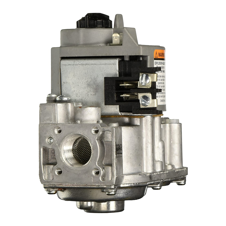
The VR8200 Continuous Pilot Dual Automatic
Valve Combination Gas Controls are used in gas-
fired, standing pilot appliances. They include safety
shutoff, a manual valve, two automatic operators, a
pressure regulator, a pilot adjustment, and a conduit
cover (VR4200 only).
VR8200 for use with 24 Vac heating appliances and
VR4200 for use with 120 Vac heating appliances
that burn natural or liquefied petroleum (LP) gas.
Capacity rated at 130 feet
sure drop [3.7 m
3
/hr at 0.25 kPa]. Maximum regu-
lated capacity is 200 feet
Minimum regulated capacity is 20 feet
[0.6 meter
3
/hour].
Solenoid-operated first automatic valve opens on
thermostat call for heat and closes when call for
heat ends.
Diaphragm-operated second automatic valve opens
under control of the regulator and closes if gas or
power supply is interrupted.
Three-position manual gas control knob has ON,
OFF, and PILOT positions.
Separate reset button must be held down to permit
gas flow while lighting pilot; can be pushed down
only in PILOT position.
All adjustments, wiring connections and pilot out-
let are accessible from the top of the gas control.
Compact size.
Straight-through body pattern; right angle adapters
available for inlet and outlet
1/2 in. inlet and 1/2 inch outlet; adapters available
for 3/8 or 3/4 inch.
Adjustable servo regulator effectively maintains
almost constant gas output pressure under wide
fluctuation in gas supply pressure.
Inlet and outlet screens included.
Pilot filter included.
VR8200; VR4200
3
/hour at 1 inch wc pres-
3
3
/hour [5.7 meter
/hour].
3
/hour
G.S. • Rev. 1-94 • ©Honeywell Inc. 1994 • Form Number 68-0046-4
VR4200
Wiring terminal block color-coded beige to identify
standing pilot models.
May be installed at any angle between 0 and 90 degrees
from the upright position, including vertically.
1/4-inch male quick-connect terminals for electri-
cal connections. Combination screw and quick-
connect terminals on TRADELINE
0° F to +175° F [-18° C to +79° C] temperature
range standard; -40° F to +175° F [-40° C to 79° C]
available.
ECO connector included with some models: also
available as accessory.
Inlet and outlet pressure taps included; both taps
accessible from top of gas control.
Standard-, slow- and step-opening models available.
Natural to LP gas conversion kit included with
TRADELINE standard and slow-opening models.
Natural to LP gas conversion kit available for non-
TRADELINE standard and slow-opening models.
LP to natural gas conversion kit available for stan-
dard and slow-opening models.
CONTENTS
Specifications ................................................ 2
Ordering Information .................................... 2
Installation .................................................... 4
Startup and Checkout .................................... 9
Maintenance ................................................ 12
Operation .................................................... 12
Service ......................................................... 15
VR8200
(TRADELINE)
®
models.
Advertisement

Related Manuals for Honeywell VR8200A


Summary of Contents for Honeywell VR8200A
-
Page 1: Table Of Contents
Installation ............ 4 fluctuation in gas supply pressure. Startup and Checkout ........9 Inlet and outlet screens included. Maintenance ..........12 Pilot filter included. Operation ............ 12 Service ............15 G.S. • Rev. 1-94 • ©Honeywell Inc. 1994 • Form Number 68-0046—4... -
Page 2: Specifications
If you have additional questions, need further information, or would like to comment on our products or services, please write or phone: 1. Your local Honeywell Residential and Building Controls Sales Office (check white pages of your phone directory). 2. Residential and Building Controls Division Customer Satisfaction Honeywell Inc., 1885 Douglas Drive North... - Page 3 Range of Field Suffix Charac- Settings Regulator Settings Adjustment Letter teristic in. wc in. wc in. wc VR8200A, M Standard- Natural 3 to 5 0.7 to 1.2 3 to 5 0.7 to 1.2 VR4200A, M opening 10.0 8 to 12...
-
Page 4: Installation
• Flanges, see Table 3. TEMPERATURE RATING: • 393200-1 ECO Connector. VR8200A,C,H,J; VR4200A,C,H: 0° F to +175° F [-18° C • 393691 Natural to LP Conversion Kit. to +79° C]. • 394588 LP to Natural Conversion Kit. - Page 5 VR8200, VR4200 INSTALLATION 4. With O-ring facing the gas control, align the screw Fig. 2—Top view of standard VR8200, VR4200 holes on the gas control with the holes in the flange. Insert gas control. and tighten the screws provided with the flange. See Fig. 5.
- Page 6 VR8200, VR4200 INSTALLATION 3. Insert bushing in gas control and thread pipe carefully 2. Mount the gas control so gas flow is in the direction into bushing until tight. of the arrow on the bottom of the gas control. Complete the instuctions below for piping, installing 3.
- Page 7 (Fig. 2). Slip the compression fitting over the tubing and slide out of the way. vided with SUPER TRADELINE models of the VR8200A. Install the Q340A as follows: NOTE: When replacing a gas control, cut off old compres- 1. Determine if the pilot burner requires a thermo-...
- Page 8 VR8200, VR4200 INSTALLATION Fig. 10—Installing thermocouple to the power Fig. 9—Always use new compression fitting. unit. GAS CONTROL BODY TIGHTEN NUT ONE TURN THERMOCOUPLE BEYOND FINGER TIGHT LEAD BURNER FITTING BREAKS OFF AND CLINCHES TUBING AS NUT IS TIGHTENED M3076A Connect Thermocouple Connect thermocouple lead as shown in Fig.
-
Page 9: Startup And Checkout
VR8200, VR4200 INSTALLATION • STARTUP AND CHECKOUT TABLE 5—MAXIMUM LENGTH OF SUPPLEMENTARY LIMIT LEADWIRES WHEN USING Q340A THERMOCOUPLE. Thermocouple Maximum Leadwire Length x 2 (wires) Length Awg No. 14 Awg No. 16 Awg No. 18 inches meters inches meters inches meters inches meters... - Page 10 VR8200, VR4200 STARTUP AND CHECKOUT CHECK AND ADJUST GAS INPUT TO MAIN 2. If a gas leak is detected, tighten the pipe connection. BURNER 3. Stand clear while lighting main burner to prevent injury caused from hidden gas leaks, which could cause CAUTION flashback in the appliance vestibule.
- Page 11 VR8200, VR4200 STARTUP AND CHECKOUT 4. If the desired outlet gas pressure or gas flow rate b. Using a screwdriver, turn the inner adjustment cannot be achieved by adjusting the gas control, check the screw clockwise to increase or counter- gas control inlet pressure using a manometer at the inlet clockwise to decrease the main burner gas...
-
Page 12: Maintenance
Contact your Honeywell sales representative to The maintenance program should include regular check- request a gas valve with corrosion resistant construction. - Page 13 VR8200, VR4200 OPERATION seat. Thus flow of gas through the second automatic valve Step-Opening Pressure Regulation (VR8200C,P and is reduced, and outlet pressure falls to the desired level. VR4200P) If outlet pressure begins to fall, the pressure regulator Step-opening gas controls actually combine two pres- diaphragm moves slightly lower allowing more gas flow sure regulators, one for the low pressure and one for the to the gas control outlet.
- Page 14 VR8200, VR4200 OPERATION Fig. 15—Position of gas control components during the thermostat on cycle. SECOND RED RESET SECOND SERVO CONTROL KNOB AUTOMATIC VALVE AUTOMATIC PRESSURE BUTTON OPERATOR OPERATOR REGULATOR SOLENOID FIRST AUTOMATIC VALVE SOLENOID SECOND AUTOMATIC OPERATOR VALVE DISC RESET BUTTON VALVE DISC PILOT OUTLET...
-
Page 15: Service
VR8200, VR4200 SERVICE Service 2. Check the pilot burner flame adjustment. Refer to the WARNING Adjust the Pilot Burner Flame section. 3. Check the wiring between the thermocouple and the FIRE OR EXPLOSION HAZARD, gas control valve operator. CAN CAUSE PROPERTY DAMAGE, 4. - Page 16 Home and Building Control Home and Building Control Helping You Control Your World Honeywell Inc. Honeywell Limited—Honeywell Limitée 1985 Douglas Drive North 740 Ellesmere Road Golden Valley, Minnesota 55422 Scarborough, Ontario M1P 2V9 QUALITY IS KEY Printed in U.S.A.
Need help?
Do you have a question about the VR8200A and is the answer not in the manual?
Questions and answers
can i add a automatic igniter to my vr8200a 2009 gas valve it has a piolt light
The Honeywell VR8200A gas valve is designed for use with a standing pilot system, meaning it relies on a continuously burning pilot light to ignite the main burner. It does not have built-in support for an automatic igniter. Adding an automatic igniter would require modifying the system, which may not be compatible with the valve’s design and could affect safety and performance. It is recommended to use the valve as designed or consult a qualified technician for possible alternatives.
This answer is automatically generated