Table of Contents
Advertisement
Quick Links
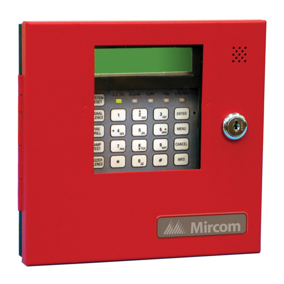
RAM-300LCD Series
Remote Annunciator
Installation and Operation Manual
System Normal
18:01 MON 2007-04-05
A.C. O N
ALARM
S UPV
TRBL
SYSTEM
RESET
SIG N AL
1
2
3
SIL EN CE
ABC
DEF
FIRE
4
5
6
D RIL L
G HI
J KL
MNO
BUZZER
7
8
9
SIL EN CE
TUV
PRS
W XY
L AMP
*
0
#
TEST
Q Z
FA-300 SERIES
Remote Annunciator
firealarmresources.com
CPU FAIL
EN TER
MEN U
CAN CEL
IN FO
LT-1002 Rev. 6
January 2018
Advertisement
Table of Contents

Subscribe to Our Youtube Channel
Related Manuals for Mircom RAM-300LCD Series


Summary of Contents for Mircom RAM-300LCD Series
- Page 1 RAM-300LCD Series Remote Annunciator System Normal 18:01 MON 2007-04-05 A.C. O N ALARM S UPV TRBL CPU FAIL SYSTEM RESET SIG N AL EN TER SIL EN CE FIRE MEN U D RIL L G HI J KL BUZZER CAN CEL...
- Page 2 firealarmresources.com...
-
Page 3: Table Of Contents
Contents Introduction Mechanical Installation Functional Setup Jumpers ......................... Potentiometer ......................... DIP Switches ........................Wiring Specifications & Features Enclosure ........................Electrical Specifications ....................Current Drain for Battery Calculations ................Environmental Specifications ..................Operating Instructions Warranty and Warning Information firealarmresources.com... - Page 4 List of Figures and Tables Figure 1 Remote Annunciator Dimensions ................... Figure 2 Mechanical Installation ....................Figure 3 Annunciator Component Descriptions ................Table 1 Jumpers ......................... Table 2 RAM-300LCD Address DIP Switch Setup ..............Table 3 DIP switch SW31 settings ....................Table 4 Maximum Wiring Run to Last Annunciator ..............
-
Page 5: Introduction
Introduction The RAM-300LCD is a remote annunciator used for the FA-300 Series and FX-350/351 Series Fire Alarm Panels. It provides remote access to the fire alarm panel. Note: Configuration of the FA-300 Series and FX-350/351 Series fire alarm panels from this remote annunciator is not allowed. -
Page 6: Mechanical Installation
Mechanical Installation To mount the RAM-300LCD open the front door, remove the dead front plate and mount the backbox to the wall using the four screws provided. This enclosure may also be mounted to a 4” square electrical box. There are two conduit areas provided at the bottom center of the enclosure. -
Page 7: Functional Setup
Functional Setup LCD CONTRAST ADJUSTMENT SYSTEM NORMAL 18:01 MON 2011-02-07 JW1, JW2, JW3 ARE FOR FACTORY USE LEAVE JUMPERS A.C. ON ALARM SUPV TRBL CPU FAIL SYSTEM JW2 AND JW3 IN RESET PLACE. SIGNAL ENTER SILENCE FIRE MENU DRILL THESE PINS ARE BUZZER CANCEL SILENCE... -
Page 8: Dip Switches
Functional Setup DIP Switches There are two DIP switches to be set. SW30 is found at the bottom right corner of the board and is used to select the annunciator address. Valid addresses are 1 to 6 inclusive for FA-300 Series, 1 to 7 for FX-350/351. -
Page 9: Wiring
Wiring To wire the RAM-300LCD, you must first remove the dead front plate. Wire from the last RAM- 300LCD to the next RAM-300LCD and so on; then from the first RAM-300LCD to the Fire Alarm Panel. There are only two connections to be made, one for power and the RS-485 loop. Replace the dead front plate once all functional setup and wiring is complete. - Page 10 Wiring The RAM-300LCD is wired as shown below. Additional RAM-300LCDs are wired in the same manner, make sure ONLY the last RAM-300LCD has the 120 ohm E.O.L. resistor connected to the RS-485 positive and negative terminals. MAKE SURE THERE IS A 120 OHM E.O.L.
-
Page 11: Specifications & Features
Specifications & Features Enclosure Enclosure may be mounted on a 4” square electrical box or on a wall. Electrical Specifications • 24 VDC nominal voltage • LCD Display, Pushbutton Controls and LED indicators. • Local Buzzer, Indicators (AC-On, Alarm, Supervisory, Trouble and CPU Fail), and Controls (System Reset, Signal Silence, Fire Drill, Buzzer Silence and Lamp Test,). -
Page 12: Operating Instructions
Operating Instructions Normal All indicators are normally OFF except for the green A.C. ON light which illuminates steadily. Alarm Operate Alarm Initiating Devices to activate Indicating Appliances. Signals will sound, common alarm will illuminate red. Silencing of Press Signal Silence button momentarily to silence all audible signals. Alarm Note: The signal silencing function may be inhibited for up to one minute. -
Page 13: Warranty And Warning Information
As the only individual in contact with system users, please bring each item in this warning to the attention of the users of this Mircom System. Failure to properly inform system end-users of the circumstances in which the system might fail may result in over-reliance upon the system. - Page 14 11. Battery Failure. If the Mircom System or any device connected to the system operates from batteries it is possible for the batteries to fail. Even if the batteries have not failed, they must be fully charged, in good condition, and installed correctly.
- Page 15 20. Integrated Products. Mircom System might not function as intended if it is connected to a non-Mircom product or to a Mircom product that is deemed non-compatible with a particular Mircom System.
- Page 16 CANADA - Main Office U.S.A © Mircom 2018 25 Interchange Way 4575 Witmer Industrial Estates Printed in Canada Subject to change without prior notice Vaughan, ON L4K 5W3 Niagara Falls, NY 14305 Tel: (905) 660-4655 Tel: (905) 660-4655 www.mircom.com (888) 660-4655...
Need help?
Do you have a question about the RAM-300LCD Series and is the answer not in the manual?
Questions and answers