Table of Contents
Advertisement
Quick Links
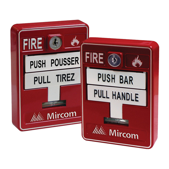
Mircom's MS-700AP(U) Series Fire Alarm Manual Stations
provide manual fire alarm activation. These high quality, die-cast
metal stations are available as single or dual-action devices. Each
station has a permanently attached AP addressable module,
which has a pair of dials for setting the address.
Specifications & Dimensions
Compatible with Mircom Fire Alarm Control Panels
Electrical Rating:
MS-702AP
Nominal Operating Voltage:
15-32 VDC
Maximum alarm current @ 24V:
5.4 mA
Average operating current @
24V: 600 µA
Dimensions:
MS-702AP: 4.93" H x 3.56" W x 2.56" D
MS-710AP(U): 4.93" H x 3.56" W x 2.9" D
Notes
• Wire as shown so that supervision of connections is
maintained.
• Maximum wire size: 12 AWG
• ADA compliant.
• To be installed per ADA 4.27.1 to 4.27.4 inclusive.
• All manual fire alarm stations shall be installed as per
the specific requirements outlined in the UL/ULC codes,
as well as all other applicable national or local codes.
Final acceptance is subject to the local authority having
jurisdiction.
Converting Double Action Manual Stations to Single
Action (MS-710AP(U) only):
Screws
Screws
1.
Using a reset key, unlock and open the manual station.
2.
Remove the smaller two screws and accompanying
brackets fastening the PUSH bar.
3.
Hold the manual station vertically with one hand with the
keyhole at the bottom. Tilt the manual station towards
you and remove the PUSH bar.
Installing the manual station
This guide covers these models:
MS-702AP Intelligent Two Stage Manual Station AP
MS-710AP(U) Intelligent Dual Action Manual Station AP
The suffix U indicates a USA version.
1
MS-710AP(U)
Nominal Operating Voltage:
15-32 VDC
Maximum alarm current @ 24V:
600 µA
Average operating current @
24V: 400 µA
MS-700AP(U) Series
Fire Alarm Manual Station
Contents of kit
MS-702AP: 4 mounting screws, 2 reset keys (black), 2 stage two
keys, 1 glass rod
MS-710AP(U): 4 mounting screws, 2 reset keys (black), 1 glass
rod
A. Wiring
Note:
The maximum wire size is 12 AWG.
1.
Connect the black (-) wire from the previous station to
the terminal that is connected to the black (-) wire from
the addressable module.
2.
Connect the black (-) wire leading the next station to the
other side of the terminal that is connected to the black
(-) wire from the addressable module.
Note:
The wires must be on opposite sides of the set screw.
Refer to Figure 2 for the location of the wires.
3.
Tighten the (-) terminal.
4.
Connect the red (+) wire from the previous station to the
terminal that is connected to the red (+) wire from the
addressable module.
5.
Connect the red (+) wire leading to the next station to the
other side of the terminal that is connected to the red (+)
wire from the addressable module.
Note:
The wires must be on opposite sides of the set screw.
Refer to Figure 2 for the location of the wires.
6.
Tighten the (+) terminal.
-
TO NEXT STATION OR
+
END OF LINE DEVICE
FROM
-
PREVIOUS
+
STATION
Figure 1: Wiring Diagram
CORRECT: BOTH
WIRES ON
OPPOSITE SIDES
OF THE SET SCREW
X
WRONG: BOTH
WIRES ON THE
SAME SIDE AS
THE SET SCREW
Figure 2: Close-up of terminals showing correct wiring
Canada
25 Interchange Way
Vaughan, ON L4K 5W3
Tel: (888) 660-4655
Fax: (888) 660-4113
www.mircom.com LT-2071 Rev. 1 Dec. 2015
-
BLACK
+
RED
ADDRESSABLE
MODULE
TO ADDRESSABLE
MODULE
TO ADDRESSABLE
MODULE
U.S.A
4575 Witmer Industrial Estates
Niagara Falls, NY 14305
Tel: (888) 660-4655
Advertisement
Table of Contents

Related Manuals for Mircom MS-700AP Series


Summary of Contents for Mircom MS-700AP Series
- Page 1 MS-700AP(U) Series Fire Alarm Manual Station Mircom’s MS-700AP(U) Series Fire Alarm Manual Stations Contents of kit provide manual fire alarm activation. These high quality, die-cast MS-702AP: 4 mounting screws, 2 reset keys (black), 2 stage two metal stations are available as single or dual-action devices. Each...
- Page 2 Move the PULL handle back to the upright position. The Close and lock the station. PULL handle should now be holding the glass rod in Reset the Fire Alarm Control Panel to reset the alarm. place. Close and lock the station. www.mircom.com LT-2071 Rev. 1 Dec. 2015...
Need help?
Do you have a question about the MS-700AP Series and is the answer not in the manual?
Questions and answers