Table of Contents
Advertisement
Quick Links
RAM-300LCD Series
Remote Annunciator
Installation and Operation Manual
System Normal
18:01 MON 2007-04-05
A.C. O N
ALARM
S UPV
TRBL
CPU FAIL
SYSTEM
RESET
SIG N AL
1
2
3
EN TER
SIL EN CE
ABC
DEF
FIRE
4
5
6
MEN U
D RIL L
G HI
J KL
MNO
BUZZER
7
8
9
CAN CEL
SIL EN CE
TUV
PRS
W XY
L AMP
*
0
#
IN FO
TEST
Q Z
FA-300 SERIES
Remote Annunciator
Advanced Life Safety Solutions
LT-1002 Rev. 4 082207
August 2007
Advertisement
Table of Contents

Related Manuals for Mircom RAM-300LCD Series


Summary of Contents for Mircom RAM-300LCD Series
-
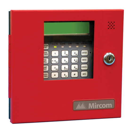
Page 1: Remote Annunciator
Advanced Life Safety Solutions RAM-300LCD Series Remote Annunciator System Normal 18:01 MON 2007-04-05 A.C. O N ALARM S UPV TRBL CPU FAIL SYSTEM RESET SIG N AL EN TER SIL EN CE FIRE MEN U D RIL L G HI... -
Page 3: Table Of Contents
RAM-300LCD Installation and Operation Manual Contents Introduction ..........................1 Mechanical Installation......................2 Functional Setup ........................3 Jumpers ..........................3 Potentiometer........................3 DIP Switches......................... 4 Wiring ............................5 Specifications & Features ....................... 7 Enclosure ..........................7 Electrical Specifications ......................7 Current Drain for Battery Calculations .................. 7 Operating Instructions...................... -
Page 5: Introduction
RAM-300LCD Installation and Operation Manual Introduction The RAM-300LCD is a remote annunciator used for the FA-300 Series and FX-350/351 Series Fire Alarm Panels. It provides remote access to the fire alarm panel. Note: Configuration of the FA-300 Series and FX-350/351 Series fire alarm panels from this remote annunciator is not allowed. -
Page 6: Mechanical Installation
Mechanical Installation Mechanical Installation To mount the RAM-300LCD open the front door, remove the dead front plate and mount the backbox to the wall using the four screws provided. This enclosure may also be mounted to a 4” square electrical box. There are two conduit areas provided at the bottom center of the enclosure. -
Page 7: Functional Setup
RAM-300LCD Installation and Operation Manual Functional Setup POTENTIOMETER FOR LCD CONTRAST ADJUSTMENT SYSTEM NORMAL 18:01 MON 2007-04-05 JW1, JW2, JW3 ARE FOR FACTORY USE LEAVE JUMPERS A.C. ON ALARM SUPV TRBL CPU FAIL SYSTEM JW2 AND JW3 IN RESET PLACE. SIGNAL ENTER SILENCE... -
Page 8: Dip Switches
Functional Setup DIP Switches There are two DIP switches to be set. SW30 is found at the bottom right corner of the board and is used to select the annunciator address. Valid addresses are 1 to 6 inclusive for FA-300 Series, 1 to 7 for FX-350/351. Set address as follows: RAM-300LCD Address DIP Switch Setup Address... -
Page 9: Wiring
RAM-300LCD Installation and Operation Manual Wiring To wire the RAM-300LCD, you must first remove the dead front plate. Wire from the last RAM-300LCD to the next RAM-300LCD and so on; then from the first RAM-300LCD to the Fire Alarm Panel. There are only two connections to be made, one for power and the RS-485 loop. - Page 10 Wiring The RAM-300LCD is wired as shown below. Additional RAM-300LCDs are wired in the same manner, make sure ONLY the last RAM-300LCD has the 120 ohm E.O.L. resistor connected to the RS-485 positive and negative terminals. MAKE SURE THERE IS A 120 OHM E.O.L.
-
Page 11: Specifications & Features
RAM-300LCD Installation and Operation Manual Specifications & Features Enclosure Enclosure may be mounted on a 4” square electrical box or on a wall. Electrical Specifications • 24 VDC nominal voltage • LCD Display, Pushbutton Controls and LED indicators. • Local Buzzer, Indicators (AC-On, Alarm, Supervisory, Trouble and CPU Fail), and Controls (System Reset, Signal Silence, Fire Drill, Buzzer Silence and Lamp Test,). -
Page 12: Operating Instructions
Operating Instructions Operating Instructions Normal: All indicators are normally OFF except for the green A.C. ON light which illuminates steadily. Alarm: Operate Alarm Initiating Devices to activate Indicating Appliances. Signals will sound, common alarm will illuminate red. Silencing of Alarm: Press Signal Silence button momentarily to silence all audible signals. Note: The signal silencing function may be inhibited for up to one minute. -
Page 13: Warranty
RAM-300LCD Installation and Operation Manual Warranty & Warning Information Warning Please Read Carefully Note to End Users: This equipment is subject to terms and conditions of sale as follows: Note to Installers This warning contains vital information. As the only individual in contact with system users, it is your responsibility to bring each item in this warning to the attention of the users of this system. - Page 14 Mircom shall not be liable for any delays, breakdowns, interruptions, loss, destruction, alteration or other problems in the use of a product arising our of, or caused by, the software.
-
Page 15: Limited Warranty
(90) days, whichever is longer. The original owner must promptly notify Mircom Technologies Ltd. in writing that there is defect in material or workmanship, such written notice to be received in all events prior to expiration of the warranty period. -
Page 16: Out Of Warranty Repairs
Products which Mircom Technologies Ltd. determines to be repairable will be repaired and returned. A set fee which Mircom Technologies Ltd. has predetermined and which may be revised from time to time, will be charged for each unit repaired. - Page 18 Notes...
- Page 20 Advanced Life Safety Solutions Canada U.S.A. © Mircom 2007 Printed in Canada 25 Interchange Way 60 Industrial Parkway PMB 278 Subject to change without prior notice Vaughan, ON L4K 5W3 Cheektowaga, NY 14227 Tel: 1-888-660-4655 Fax: 1-888-660-4113 www.mircom.com Tel: 905-660-4655 Fax: 905-660-4113...
Need help?
Do you have a question about the RAM-300LCD Series and is the answer not in the manual?
Questions and answers