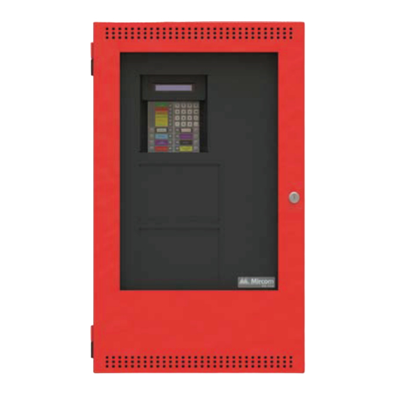
Mircom FX-350 Series User Manual
Analog/addressable fire alarm panels
Hide thumbs
Also See for FX-350 Series:
- Installation and operation manual (72 pages) ,
- Programming manual (48 pages) ,
- User manual (20 pages)

Related Manuals for Mircom FX-350 Series


Summary of Contents for Mircom FX-350 Series
- Page 1 FX-350 Series Analog/Addressable Fire Alarm Panels LT-965 Rev. 3.2 User Guide March 2018...
-
Page 3: Table Of Contents
FX-350/351/353 Series User Guide Table of Contents Introduction ..........................1 About this Manual ......................... 1 Technical Support ......................... 1 Main Display ..........................2 The Buzzer and Common LED Indicators................3 Buzzer........................... 3 AC ON LED........................... 3 Common Alarm LED ......................3 Common Supervisory LED .................... -
Page 5: Introduction
Refer to the Glossary on page 10 for an explanation of commonly used terms in this manual. Technical Support For all technical support inquiries, please contact Mircom’s Technical Support Department between 8 A.M. and 5 P.M. (EDT) Monday through Friday, excluding holidays. -
Page 6: Main Display
Main Display Main Display Refer to the diagram below for the LCD display, LED indicators, and control buttons locations. SYSTEM NORMAL MAR 21, 2013 02 :41AM AC ON COMMON ALARM COMMON S UP V COMMON TROUBLE CP U FAULT GROUND FAULT S Y S TE M S IGNAL... -
Page 7: The Buzzer And Common Led Indicators
FX-350/351/353 Series User Guide The Buzzer and Common LED Indicators Buzzer The buzzer sounds if there is a fire alarm, a supervisory alarm, or a trouble in the fire alarm system. It turns OFF if the condition causing AC ON the buzzer to sound goes away or the ALM/SUP/TBL/BLDG AUDIBLE button is pressed. -
Page 8: Main Display Buttons And Leds
Main Display Buttons and LEDs Main Display Buttons and LEDs System Reset Button The System Reset button resets the fire alarm control panel and all circuits. The System Reset LED turns ON steady for the duration of the reset operation. This S Y S TE M RE S E T button is also used to confirm Positive Alarm Sequence (if implemented). -
Page 9: Battery/Charger Trouble Button
FX-350/351/353 Series User Guide Battery/Charger Trouble Button The Battery/Charger Trouble LED will flash amber at the trouble rate when battery BATTERY/CHARGER charger voltage is below 20.4V (below nominal 24V). The Battery/Charger Trouble TROUBLE button is non-functional. The Up and Down Arrow Buttons Use these buttons to scroll through any events listed on the screen. -
Page 10: Understanding On-Screen Messages
Understanding On-screen Messages Understanding On-screen Messages The LCD screen of the fire alarm control panel displays messages regarding system events. System events display on the screen in a queue. Events in this queue are listed on the screen in order of priority: alarms are of highest priority, followed by supervisory, trouble, and property and building safety (monitor) conditions. -
Page 11: Common Messages
FX-350/351/353 Series User Guide Common Messages Common system messages are outlined below. AC Power Fail The “AC Power Fail” message indicates that the power has dropped below the minimum level and the system is running on backup battery power. The trouble is removed when the power returns to the normal value. Trouble Type Trouble code Trouble Info... - Page 12 Understanding On-screen Messages Data Link Trouble The “Data Link Error” message can display for one of two reasons: either the main panel and annunciator failed to communicate with each other or an unconfigured remote annunciator is communicating with the main panel. In both cases, the following trouble message is displayed: Trouble Type Trouble code...
- Page 13 FX-350/351/353 Series User Guide Auxiliary Power Supply The “Aux. Power Supply” message indicates that the panel has detected a short on the auxiliary power supply, the power is cut it off and a trouble message is generated. Press to restore power to the system. If the short is SYSTEM RESET removed, the panel will return to normal;...
-
Page 14: Glossary
Glossary Glossary Alarm Condition Occurs when devices such as detectors, pull stations, or sprinklers are activated. In a single stage system, this condition will activate all signalling devices throughout the building. In a two stage system, this condition will activate an alert signal and the General Alarm timer. - Page 15 FX-350/351/353 Series User Guide Trouble Flash Rate 20 flashes per minute is the rate at which an LED will flash to indicate a trouble condition. Walk Test A test performed by a technician to ensure that each detection device is connected to the panel and working properly. Zones A fire alarm protected area that consists of at least one circuit.
-
Page 16: Warranty And Warning Information
Some reasons for system failure include the following. As the only individual in contact with system users, please bring each item in this warning to the attention of the users of this Mircom System. Failure to properly inform system end-users of the circumstances in which the system might fail may result in over-reliance upon the system. -
Page 17: Note To Users
Signals being communicated by a Mircom System may not reach the receiver if an item (such as metal, water, or concrete) is placed on or near the radio path. Deliberate jamming or other inadvertent radio signal interference can also negatively affect system operation. -
Page 18: Warranty
18. Telephone Lines Malfunction. Telephone service can cause system failure where telephone lines are relied upon by a Mircom System. Alarms and information coming from a Mircom System may not be transmitted if a phone line is out of service or busy for a certain period of time. Alarms and information may not be transmitted where telephone lines have been compromised by criminal tampering, local construction, storms or earthquakes. - Page 19 FX-350/351/353 Series User Guide...
- Page 20 CANADA - Main Office U.S.A © Mircom 2018 25 Interchange Way 4575 Witmer Industrial Estates Printed in Canada Subject to change without prior notice Vaughan, ON L4K 5W3 Niagara Falls, NY 14305 Tel: (905) 660-4655 Tel: (905) 660-4655 www.mircom.com (888) 660-4655...
Need help?
Do you have a question about the FX-350 Series and is the answer not in the manual?
Questions and answers