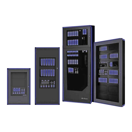
Mircom FlexNet FX-4000 User Manual
Intelligent fire detection and voice evacuation system
Hide thumbs
Also See for FlexNet FX-4000:
- Configurator manual (178 pages) ,
- Installation and operation manual (154 pages)

Related Manuals for Mircom FlexNet FX-4000


Summary of Contents for Mircom FlexNet FX-4000
- Page 1 FX-4000 Intelligent Fire Detection and Voice Evacuation System LT-893MP Rev. 0 User Guide September 2021...
-
Page 3: Table Of Contents
Table of Contents Introduction About this Manual ......................Front Panel Indicators, Controls, and Operation Front Panel Indicators and Control Locations (Model DSPL-420DS) ......Graphic Front Panel Indicators and Control Locations (Model DSPL-2440) ....Front Panel Indicators and Control Locations (Model DSPL-420-16TZDS) ....Common Indicators ...................... - Page 4 Table of Contents Microphone Paging Operation Making a Page ....................... Making an All Call ......................Page to Evac ........................Page to Alert ........................Making a Warden Page (Page by Phone) ..............Telephone Operation Answering the Telephone ....................Making a Call from a Master Telephone ................ Making a Call to a Master Telephone ................
-
Page 5: Introduction
Introduction About this Manual This user guide provides information on the Command Menu features of the FleX-Net™ FX-4000 Intelligent Fire Detection and Voice Evacuation System. Using the instructions provided in this manual, you will be able to: • Print reports •... -
Page 6: Front Panel Indicators, Controls, And Operation
Front Panel Indicators, Controls, and Operation Front Panel Indicators and Control Locations (Model DSPL-420DS) LCD Display - four lines, Cursor buttons, ENTER, MENU, 20 characters per line CANCEL, INFO Indicators for AC On, CPU Fault, and Ground Fault FleX-Net MP Fire Control System - System Normal - May 04, 2020 12:00:00... -
Page 7: Graphic Front Panel Indicators And Control Locations (Model Dspl-2440)
Front Panel Indicators, Controls, and Operation Graphic Front Panel Indicators and Control Locations (Model DSPL-2440) Graphic Display - 24 lines, 40 characters per line Indicators for AC On, CPU Fault, and Ground Fault Cursor buttons: ENTER, MENU, CANCEL, INFO Queue controls and indicators for Two configurable switches and Controls and Indicators for Signal Alarm, Supervisory, Trouble, and... -
Page 8: Common Indicators
Front Panel Indicators, Controls, and Operation LED indicators are amber (trouble or supervisory), red (alarm), or green (AC ON), and may illuminate continuously (steady) or at one of two flash rates: • Fast flash: 120 flashes per minute, 50% duty cycle •... - Page 9 Front Panel Indicators, Controls, and Operation 2.4.4 Supervisory Queue LED The Supv. (Supervisory) LED flashes amber when there is a supervisory alarm in the panel resulting from any latching or non-latching supervisory circuit. The LED turns OFF if all non- latching supervisory circuits are restored and there are no active latching supervisory circuits.
-
Page 10: Display Controls
Front Panel Indicators, Controls, and Operation 2.4.13 Acknowledge (or Automatic Alarm Signal Silence or Automatic Alarm Signal Stop) LED If the panel is configured as a Two Stage system, the Acknowledge LED flashes amber at the fast flash rate while the General Alarm timer is timing. It turns ON steady amber after the Auto General Alarm Timer is cancelled by the activation of the Acknowledge or Signal Silence buttons. - Page 11 Front Panel Indicators, Controls, and Operation • Press the Building Queue Button to cycle through all the unacknowledged building (monitor) conditions. Press to cycle through all queued monitor conditions, both acknowledged and unacknowledged. Press the right cursor button to scroll up by 10 events at a time. Press the left cursor button to scroll down by 10 events at a time.
-
Page 12: Common Controls
• Resets devices activated by input simulation and manual control Attention: The System Reset can be global (all control panels) or by defined Node group (one or more Nodes) as programmed using Mircom’s MGC-4000 Configurator Software. 2.6.5 Acknowledge Button (Two Stage Only) If the panel is not configured for Two Stage operation, this button could be configured for a different operation. - Page 13 2.6.7 Configurable Switches and LEDs These two switches and LEDs can be used for any function listed in the Mircom’s MGC-4000 Configurator Software. Such functions include Buzzer Silence, Auxiliary Disconnect, Total Evacuation, Bypass, System Inputs, and switching the display language (toggle between two...
-
Page 14: Troubleshooting
Reload the Configurator, or reboot the system by powering it down and then (RAM) powering it up. This message appears if the system is overloaded and risks resetting itself. If Configuration Data Error this error should occur, please report it to Mircom’s Technical Support (FLASH) Department. -
Page 15: Start Up
The fourth line is the firmware version. Let the system initialize for approximately one to two minutes. Download the configuration at each Node using a laptop computer and Mircom’s MGC-4000 Configurator. Once all the Nodes have been downloaded, connect the network and select the Network Restart (see page 56) at the CACF (Central Alarm and Control Facilities) or main node. -
Page 16: Passcodes
Start Up Passcodes ENTER MENU MGC Network Fire Alarm Control Panel CANCEL Normal Condition INFO June 17, 2020 BLDG QUEUE QUEUE QUEUE QUEUE THESE BUTTONS REPRESENT THE CORRESPONDING NUMBER IN THE MENU MODE Pressing the Alarm Queue button represents the number 0 Pressing the Supv. -
Page 17: Menu Mode
Start Up Level 1 • Device bypass • Zone bypass • Node bypass • Buzzer bypass • Set time • Walktest Level 2 • Clear event logs • Clear verification counters • Configuration change • Network restart • Manual control •... - Page 18 Start Up Menu Submenu Description How to Use Device/Circuit Bypass or unbypass a device or circuit. See page 33 Node Bypass or unbypass a node. See page 34 Loop Bypass or unbypass a loop. See page 35 Relay disc Disconnect or reconnect all relays. See page 36 Input Zone Disconnect or reconnect an input zone.
- Page 19 Start Up Note: If you have used the Configurator to program the “Manual Control Enable” option in the Command Menu, the Command Menu list appears differently than what is shown above. Menu option 3 is “Man Ctrl Enable”, and “Manual Control” is option 4.
-
Page 20: Front Panel Menu Operation
Front Panel Menu Operation 1. Reports Menu Use the Reports Menu to print the Alarm Log, Event Log, Current Levels, Sensitivity Levels, Verification Counts, Maintenance Report, Obscuration, CO Report, Serial Code, Power Source, and Output Active. You can view on screen, or print directly to a printer connected to the panel, or to your laptop computer. - Page 21 Front Panel Menu Operation Step 3: Select the option you want to view - Report Menu - 1. Use to scroll the cursor through the 1 Alarm Log menu. 2 Event Log 3 Current Levels 2. Press to select an option. 4 Sensitivity lev 5 Verif Count 6 Maint.
- Page 22 Front Panel Menu Operation 5.1.2 Event Log The event log reports on all events: alarms, troubles, and button pushes. Events are listed in order of the latest (most recent) event to the earliest. The maximum number of recorded event log entries is 5000. Step 1: Select the event log 1.
- Page 23 Front Panel Menu Operation Step 2: Print or view the current levels • To print the Current Levels report to the printer, press when the cursor flashes beside - Report to - “Printer”. 1 Printer • To view the Current Levels report on the screen, 2 Screen press then...
- Page 24 Front Panel Menu Operation 5.1.4 Sensitivity Level The sensitivity level report is used for annual inspection to validate against a measured sensitivity. The report displays all detectors on the specified node, card and loop, that have a sensitivity configured. Step 1: Select Sensitivity Level 1.
- Page 25 Front Panel Menu Operation 5.1.5 Verification Count This option reports on any pre-alarmed devices that are set to verification mode. This report lists each time a device goes into pre-alarm status. If no devices are set to verification mode, then no report appears. Step 1: Select Verification Count 1.
- Page 26 Front Panel Menu Operation If the display shows... • Press and hold for more information on the Verified Count. Node 1 Card 1 Lp 1 01-01-011N-S001.001 • to scroll the cursor (CLIP)Heat Det through the log. Verif. Count: 0 • Press to exit to the Reports Menu.
- Page 27 Front Panel Menu Operation If the display shows... No dirty devices found..the display returns to the Reports Menu. If the display shows... • Press and hold to view the details. Node 1 Card 1 Lp 1 01-01-011N-S001.001 • to scroll the cursor (CLIP)Heat Det through the records.
- Page 28 Front Panel Menu Operation Step 3: Select a node, card, and loop 1. Use to scroll through the numbers. 2. Select the node number, then press Select Node, Card & Loop Node:ALL 3. Select the card number, then press 4. Select the loop number, then press •...
- Page 29 Front Panel Menu Operation Step 3: Select a node, card, and loop 1. Use to scroll through the numbers. 2. Select the node number, then press Select Node, Card & Loop Node:ALL 3. Select the card number, then press 4. Select the loop number, then press •...
- Page 30 Front Panel Menu Operation Step 2: Print or View Serial Code • To print the Serial Code report to the printer, press when the cursor flashes beside - Report to - “Printer”. Go to Step 3. 1 Printer 2 Screen •...
- Page 31 Front Panel Menu Operation Step 2: Select node • Select a node number by using Select Node, Card & Loop to scroll through the numbers, or Node:ALL • Select all nodes by pressing Step 3: Power source report The power source is displayed as per this example. Node 03 Battery: 22.50 V to scroll the scroll through the...
-
Page 32: Bypass Menu
Front Panel Menu Operation Step 3: Select node • Select a node number by using - Select Node - to scroll through the numbers, or Node:ALL • Select all nodes by pressing An example of the information displayed on screen is shown on the left. - Page 33 Front Panel Menu Operation The following subsections provide instructions on using each Bypass Menu option. 5.2.1 Device/Circuit Bypass Use this option if you want to bypass or unbypass a device or circuit from the panel. Usually this is done when you need to add, remove, repair, or investigate a device or circuit. To unbypass the device or circuit, follow the same procedure for device/circuit bypass.
- Page 34 Front Panel Menu Operation Step 5: Bypass the device or circuit The system asks whether or not you want to bypass or unbypass the device. N2-C1-L1-D18-CKI1 O2-01IN-018.001 1. Use to select “yes” or “no”. Bypass?Y 2. Press to continue. At this point the display varies, depending on your choice: •...
- Page 35 Front Panel Menu Operation Step 3: Bypass the node The system asks whether or not you want to bypass or unbypass the node. Bypass?Y 1. Use to select “yes” or “no”. 2. Press to continue. At this point the display varies, depending on your choice: •...
- Page 36 Front Panel Menu Operation At this point the display varies, depending on your choice: • If you selected “yes”, the display shows either the message “Loop bypassed” or “Loop unbypassed”, then it returns to the Command Menu. • If you selected “no”, the display shows the message “Operation cancelled”, then it returns to the Command Menu.
- Page 37 Front Panel Menu Operation Step 2: Select a node 1. Use to select the node number. - Select Node - Node: 1 2. Press to continue. Step 3: Select a zone 1. Use to select the zone. - Select Zone - Tag 1 Tag 2 2.
- Page 38 Front Panel Menu Operation To unbypass the output zone, follow the same procedures for output zone bypass. Step 1: Select Input Zone Bypass 1. Use to scroll to “Output Zone”. - Bypass Menu - 4 Relay Disc 5 Input Zone 2.
- Page 39 Front Panel Menu Operation 5.2.9 Node Outputs This option is useful if you want to bypass all the outputs of a node. To unbypass the outputs of a node, follow the same procedures for Node Outputs bypass. Step 1: Select Node Outputs Bypass 1.
- Page 40 Front Panel Menu Operation Step 2: Bypass the positive alarm sequence The system asks whether or not you want to bypass or unbypass the positive alarm sequence. Pos. Alm. Sequence Unbypassed. 1. Use to select “yes” or “no”. Bypass?Y 2. Press to continue.
-
Page 41: Alternate Menu Option #3: Manual Control Enable
Front Panel Menu Operation 5.2.12 Audio This option is useful if you want to bypass or un-bypass all audio signals going to amplifiers in the system. Step 1: Select Audio Bypass 1. Use to scroll to “Audio”. - Bypass Menu - 8 Pos. -
Page 42: Manual Control
Front Panel Menu Operation 5.3.1 Selecting Manual Control Enable from the Menu Step 1: Select Manual Enable - Command Menu- 1. Use to scroll the cursor to “Man 1 Reports Ctrl Enable”. 2 Bypass 3 Man Ctrl Enable 2. Press to continue. -
Page 43: Input Simulation
Front Panel Menu Operation Step 2: Enter your passcode (if required) Enter passcode for Enter your passcode. See page 16 for instructions on level 1 or higher: entering passcodes. Step 3: Select output 1. Use to scroll through the choices, then press to make a selection. -
Page 44: Alternate Menu Option #5: Unlock Com Control
Front Panel Menu Operation Step 2: Enter your passcode (if required) Enter passcode for Enter your passcode. See page 16 for instructions on level 1 or higher: entering passcodes. Step 3: Select node, card, and loop 1. Use to scroll through the choices, - Select Device - and then press to make a selection. - Page 45 Front Panel Menu Operation appears when attempting to perform a walk test. If you are using a single node system, then the panel supports a default walk test of all devices, if no areas are defined in the configuration. The audible walk test is only supported by the default walk test on a single node system.
- Page 46 Front Panel Menu Operation Step 2: Select the walk test configuration 1. Use to scroll the cursor through the menu. - Walktest - 1st Floor 2. Press to select a Walk Test Configuration. 2nd Floor Press to exit and return to the Command Menu. Step 3: Start the walk test Start or Resume Test for device inspection.
- Page 47 Front Panel Menu Operation 5.7.2 Audible Test (Single Node System) During this test, alarm activation of any input device activates all signals for one half second. Trouble activation on any input device activates all signals continuously for one second. If audio amplifier is configured for alarm and trouble events, it sounds words “Alarm”...
- Page 48 Front Panel Menu Operation Step 5: Main walk test screen During the Walk Test the display is as shown. A = number of Walk Test alarm events T = number of Walk Test trouble events D = number of duplicate alarm and trouble events OneMan R = number of remaining alarm and trouble events from A:xxxx D:xxxx R:xxxx...
- Page 49 Front Panel Menu Operation 5.7.3 Silent Test (Single Node System) During this test, alarm activation of any input device activates all signals for one half second. Trouble activation on any input device activates all signals continuously for one second. If audio amplifier is configured for alarm and trouble events, it sounds words “Alarm”...
- Page 50 Front Panel Menu Operation Step 5: Main walk test screen During the Walk Test the display is as shown. A = number of Walk Test alarm events T = number of Walk Test trouble events D = number of duplicate alarm and trouble events OneMan R = number of remaining alarm and trouble events from A:xxxx D:xxxx R:xxxx...
- Page 51 Front Panel Menu Operation Step 2: Walk test report on screen • to scroll the cursor One Man(or 1st Floor) A:nnnn D:nnnn R:nnnn through the Walk Test log. T: nnnn D:nnnn R:nnnn Press CANCEL to end Press to exit and return to the Command Menu. Step 3: Walk test device report on screen Device display is as shown.
- Page 52 Front Panel Menu Operation The following is an example of a printed Walk Test Report:...
-
Page 53: Day/Night Mode
Front Panel Menu Operation 6. Day/Night Mode Using the Configurator, you can program day mode and night mode separately for different system sensitivity levels. Select the Day/night mode option in the Command Menu if you want to manually set the Day/ night mode. -
Page 54: Set Time
Front Panel Menu Operation Note: The panel stays in the mode you select until you change it to another mode. 7. Set Time Note: To set the date, you must use the Configurator. Step 1: Select Set Time 1. Press to select the Command Menu. -
Page 55: Clear Verification Counter
Front Panel Menu Operation Step 1: Select Clear Event Log 1. Press to select the Command Menu. - Command Menu- 6 Day/Night mode 2. Use to scroll the cursor to “Clear 7 Set Time Event Log”. 8 Clear Event Log 3. -
Page 56: Network Restart
Front Panel Menu Operation Step 3: Select “yes” or “no” 1. Use to select “yes” or “no”. Clear all verification counters?Y 2. Press to continue. At this point the display varies, depending on your choice: • If you selected “yes”, the display shows the message “Counters cleared “, then it returns to the Command Menu. -
Page 57: Configuration
Front Panel Menu Operation 5.13 11. Configuration Select this option if you want to see the information regarding the configuration in the system. Step 1: Select Configuration 1. Use to scroll the cursor to - Command Menu - 9 Clr Verif Count “Configuration”. - Page 58 Front Panel Menu Operation 5.13.2 Select Version Select this option if you want to select the configuration version to make active. Step 1: Select Choose Configuration 1. Use to scroll the cursor to “Select - Configuration - 1 Config Info Version”.
-
Page 59: Signal Silence Inhibit Timer
Front Panel Menu Operation 5.13.3 Factory Attention: If you select this option, all the configuration information on the system will be erased. Use the Factory option to reset the panel to its factory default settings. Step 1: Select Choose Configuration 1. -
Page 60: Reading Component Ids
Front Panel Menu Operation Step 1: Select Signal Silence Inhibit Timer 1. Use to scroll the cursor to “Sig Sil - Command Menu 10 Network Restart Inh Tmr”. 11 Configuration 12 Sig Sil Inh Tmr 2. Press to continue. Step 2: Enter your passcode (if required) Enter passcode for Enter your passcode. - Page 61 Front Panel Menu Operation • Opt - Output circuit • IZ - Input zone • OZ - Output zone • IT - Custom Interval • TM - Custom Timer • ST - Common System Status • NS - Local Node Status •...
- Page 62 Microphone Paging Operation Making a Page 1. Select a zone on the page selector. 2. Remove the microphone from its holder and press and hold the button on the microphone. 3. Speak into the microphone when the Page Ready LED is illuminated on the microphone panel.
- Page 63 Telephone Operation Answering the Telephone 1. When any telephone zone rings (the local buzzer sounds intermittently, and the green zone LED and Incoming Call LED flash), press that zone's button on the telephone selector panel once to answer. Once any one zone has been answered, calls from any other zone causes that zone's green LED and the Incoming Call LED at the master telephone to flash and the buzzer to sound.
- Page 64 CANADA - Main Office U.S.A © Mircom 2021 25 Interchange Way 4575 Witmer Industrial Estates Printed in Canada Subject to change without prior notice Vaughan, ON L4K 5W3 Niagara Falls, NY 14305 Tel: (905) 660-4655 Tel: (905) 660-4655 www.mircom.com (888) 660-4655...
Need help?
Do you have a question about the FlexNet FX-4000 and is the answer not in the manual?
Questions and answers