Table of Contents

Related Manuals for Nibe DRAZICE TO/E 5.1 UP/IN


Summary of Contents for Nibe DRAZICE TO/E 5.1 UP/IN
- Page 1 OPERATING AND INSTALLATION MANUAL ELECTRIC WATER HEATER TO/E 5.1 UP/IN TO/E 10.1 UP/IN Družstevní závody Dražice-strojírna s.r.o. Dražice 69, 294 71 Benátky nad Jizerou tel.: +420 / 326 370 911 fax: +420 / 326 370 980 e-mail: export@dzd.cz...
-
Page 2: Table Of Contents
CONTENTS PRODUCT ACCESSORIES ..........................5 MESSAGE FOR CUSTOMERS ........................5 TECHNICAL DESCRIPTION .......................... 5 GENERAL TECHNICAL DATA ........................6 OPERATING ACTIVITY ..........................6 WALL MOUNTING ............................6 PLUMBING FIXTURE ........................... 7 ELECTRIC INSTALLATION ..........................9 HEATER COMMISSIONING ......................... 9 10 IMPORTANT NOTICE ..........................10 10.1 DISPOSAL OF PACKAGING MATERIAL AND FUNCTIONLESS PRODUCT ........... - Page 3 16 FIGURES ..............................17 16.1 HEATER DIMENSIONS ........................17 16.2 ELECTRICAL WIRING DIAGRAM ....................... 18 - 3 -...
- Page 4 CAREFULLY READ THIS MANUAL BEFORE INSTALLING THE WATER HEATER! Dear Customer, Družstevní závody Dražice - strojírna s.r.o., would like to thank you for your decision to use a product of our brand. With this guide, we will introduce you to the use, construction, maintenance and other information on electrical water heaters.
-
Page 5: Product Accessories
1 PRODUCT ACCESSORIES The product is packed together with service instructions. The heater is equipped with a safety valve as a protective element. The valve is mounted on the cold water supply (see chapter 7- PLUMBING FIXTURE). 2 MESSAGE FOR CUSTOMERS This electric heater is designed for preparation of hot water in households, cottages, and various welfare facilities. -
Page 6: General Technical Data
4 GENERAL TECHNICAL DATA TO/E 5.1 IN/UP TO/E 10.1 IN/UP VOLUME RATED PRESSURE ELECTRIC CONNECTION 1 PE-N 230V/50HZ RECOMMENDED BREAKER 16 A INPUT 1500 EL. PROTECTION IP X5 MAX WEIGHT OF THE HEATER 6.0 (10.6) 8.0 (17.6) WITHOUT WATER TIME OF EL. HEATING FROM 10 °C TO 60 °C MIXED WATER V40 4.06 / 5.51... -
Page 7: Plumbing Fixture
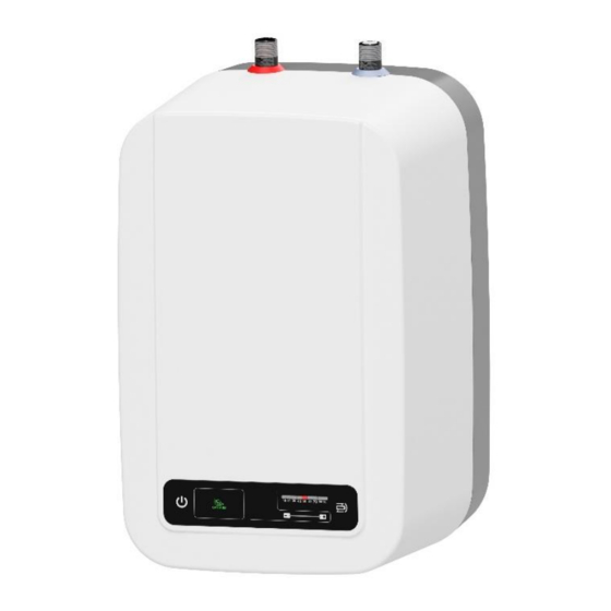
7 PLUMBING FIXTURE Water inflow and outflow is indicated with different colour terminals on the heater tubes. Cold water supply is indicated with blue and hot water outflow is indicated with red. There are two ways of connecting the water heater to water network. Closed, pressure connection system allows water withdrawal at multiple supply (withdrawal) points whilst open flow system allows one supply (withdrawal) point only. - Page 8 Safety valve is mounted on the cold water inlet identified with a blue ring. Each hot service water pressure heater must have a safety valve with a membrane spring. Nominal clearance of safety valves is defined in the ČSN 0 60830 standard. The safety valve must be well accessible, as near to the heater as possible. The input pipes must have at least the same clearance as the safety valve.
-
Page 9: Electric Installation
We recommend that the hot water distribution from the heater was as short as possible to minimise heat losses. Heaters TO/E UP must be provided with a discharge valve mounted on the cold service water inlet to the heater for potential disassembly or repair. When assembling the security equipment, follow the standard. -
Page 10: Important Notice
10 IMPORTANT NOTICE - Without a confirmation issued by an authorised company about performed electrical and plumbing fixture the warranty certificate shall be void. - The hot water outlet must be equipped with a combination faucet. - It is not allowed to handle the thermostat in any manner whatsoever, aside from temperature resetting with a control button. -
Page 11: Functional Defects
11 FUNCTIONAL DEFECTS DEFECT FAILURE • LED is on • heating element failure Water in the tank is cold Water in the tank is not warm • LED is on • heating element failure enough • operating thermostat failure safety thermostat shut off power supply •... -
Page 12: Use And Maintenance Of Heater
13 USE AND MAINTENANCE OF HEATER Once connected to the water and power supply networks, the heater is ready for use. The electric heater operation is indicated by an indicator that is on until the water in the heater is heated to the set temperature. -
Page 13: Installation Regulations
14 INSTALLATION REGULATIONS Both the electric and water installation must follow and meet the requirements and regulations relevant in the country of use! 15 CONTROL PANEL 15.1 CONTROL PANEL DESCRIPTION An example of the LITE front panel can be seen in Figure 2. This panel is most often designed in two versions, either horizontal (shown in the figure) or vertical. -
Page 14: Switch
The front panel is equipped with a protective foil which must be removed for proper readability of the panel. 15.2.1 SWITCH This is an indicator symbol with an integrated button that is used to turn the heater on and off. If the heater is turned off (but connected to the network), this symbol is slightly backlit to make it easier to find, for example, in dark places. -
Page 15: Controls And Settings
15.3 CONTROLS AND SETTINGS All controls of the heater are carried out using the front panel with the capacitive touch buttons described above. 15.3.1 TURNING THE HEATER ON On initial start-up, the heater is off by default. This can be recognized by the Switch 1 icon slightly backlit to make it easier to find in dark places. -
Page 16: Error Messages
15.4 ERROR MESSAGES As part of its operation, the heater is able to detect several error conditions indicated on its front panel. If a critical error occurs, the heating is stopped. The error can be cleared by turning the heater off and on using the switch (1). -
Page 17: Termostat Modes
15.5 TERMOSTAT MODES 15.5.1 HEATING MODE Active thermostat mode where the thermostat keeps the temperature of the heated water at the value set by the user with the given hysteresis. The user can set this value on the control panel. 15.5.2 NON-FREEZE TEMPERATURE MODE This is a mode to prevent the water from freezing in the heater, for example in the winter months. - Page 18 16.2 ELECTRICAL WIRING DIAGRAM Figure 4 15-9-2021 - 18 -...
Need help?
Do you have a question about the DRAZICE TO/E 5.1 UP/IN and is the answer not in the manual?
Questions and answers