Advertisement
Quick Links
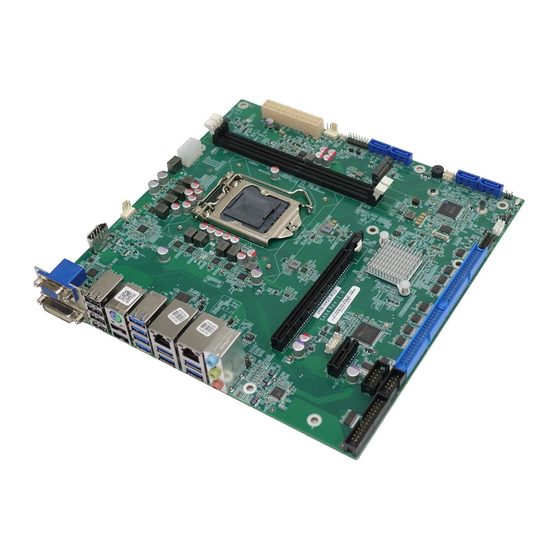
microATX motherboard supports 14nm LGA1200 10th/11th
Generation Intel® Core™ i9/i7/i5/i3, Celeron® and Pentium®
processor, DDR4, triple independent displays, 2.5GbE LAN, M.2,
8 USB 3.2, 6 USB 2.0, 10 COM, SATA 6Gb/s, HD Audio and RoHS
Quick Installation Guide
Package List
IMB-Q470 package includes the following items:
1 x IMB-Q470 single board computer
2 x SATA cable
1 x I/O shielding
1 x QIG
IMB-Q470
Version 1.0
August 10, 2023
©2023 Copyright by IEI Integration Corp.
All rights reserved.
Advertisement

Related Manuals for IEI Technology IMB-Q470


Summary of Contents for IEI Technology IMB-Q470
- Page 1 8 USB 3.2, 6 USB 2.0, 10 COM, SATA 6Gb/s, HD Audio and RoHS IMB-Q470 Quick Installation Guide Version 1.0 August 10, 2023 Package List IMB-Q470 package includes the following items: 1 x IMB-Q470 single board computer 2 x SATA cable ...
-
Page 2: Specifications
Specifications CPU: LGA1200 socket supports 10th/11th generation Intel® Core™ i9/i7/i5/i3, Pentium® or Celeron® processor, up to 125W TDP System Chipset: Intel® Q470 / Q470E Memory: Two 288-pin 2933 MHz dual-channel DDR4 SDRAM unbuffered DIMMs slots supporting up to 64GB ... - Page 3 1 x Analog audio (2x5 pin) Front Panel: 1 x Front panel (2x7 pin, power LED, HDD LED, speaker, power button, reset button) LAN LED: 2 x LAN LED (1x2 pin) Expansions: 1 x PCIe Gen3 x16 2 x PCIe Gen3 x4 1 x M.2 B key 2242/2280 (PCIe Gen3 x2) 1 x M.2 M key 2242/2280 (PCIe Gen3 x4)
-
Page 4: Ordering Information
High-performance LGA1155/1156/1200 cooler kit, 95W IEI Resource Download Center All the drivers and utility for the https://download.ieiworld.com IMB-Q470 are available on IEI Resource Download Center. Type IMB-Q470 and press Enter to find all the relevant software, utilities, and documentation. To... -
Page 5: Jumpers Setting And Connectors
Jumpers setting and connectors LABEL FUNCTION ME_RTC2 Clear CMOS jumper ME_RTC1 Clear ME jumper J_ATX_AT1 AT/ATX power mode setting switch J_FLASH1 Flash descriptor security override jumper CPU12V1 +12V power source connector ATX1 24-pin ATX power source connector AUDIO1 Audio connector DIO1 Digital I/O connector CHASSIS1... - Page 6 External VGA female connector and DVI-D U142 connector LAN1_USB1, LAN2_USB2 External RJ-45 LAN and dual USB 3.2 Gen 1 connector External keyboard/mouse and dual USB 2.0 K/M_USB1 connector USB_CN1 External quad-port USB 2.0 connector CN_USB30 External quad-port USB 3.2 Gen 1 connector ME_RTC2: Clear CMOS Jumper PIN NO.
- Page 7 CPU12V1: +12V Power Source Connector PIN NO. DESCRIPTION PIN NO. DESCRIPTION +12V +12V +12V +12V ATX1: 24-pin ATX Power Source Connector PIN NO. DESCRIPTION PIN NO. DESCRIPTION +3.3V +3.3V +3.3V -12V PS_ON Power good 5VSB +12V +12V +3.3V AUDIO1 : Audio Connector PIN NO.
- Page 8 DIO1 : Digital Input/Output Connector PIN NO. DESCRIPTION PIN NO. DESCRIPTION Output 3 Output 2 Output 1 Output 0 Input 3 Input 2 Input 1 Input 0 CHASSIS1: Chassis Status Connector DESCRIPTION DESCRIPTION +3.3VSB CHASSIS OPEN CPU_FAN1: CPU Fan Connector PIN NO.
- Page 9 LED_LAN1: LAN1 Link LED Connector DESCRIPTION DESCRIPTION +3.3V LAN1_LED_LNK#_ACT LED_LAN2: LAN2 Link LED Connector DESCRIPTION DESCRIPTION +3.3V LAN2_LED_LNK#_ACT LPT1: Parallel Port Connector PIN NO. DESCRIPTION PIN NO. DESCRIPTION SIO_AFD# RPD0 SIO_ERR# RPD1 SIO_INIT# RPD2 SIO_SLIN# RPD3 RPD4 RPD5 RPD6 RPD7 SIO_ACK# SIO_BUSY SIO_PE...
- Page 10 COM1-4: Quad-port RS-232 Connector PIN NO. DESCRIPTION PIN NO. DESCRIPTION DCD1 DSR1 RXD1 RTS1 TXD1 CTS1 DTR1 GND1 GND1 DCD2 DSR2 RXD2 RTS2 TXD2 CTS2 DTR2 GND2 GND2 DCD3 DSR3 RXD3 RTS3 TXD3 CTS3 DTR3 GND3 GND3 DCD4 DSR4 RXD4 RTS4 TXD4 CTS4...
- Page 11 GND8 GND8 DCD9 DSR9 RXD9 RTS9 TXD9 CTS9 DTR9 GND9 GND9 DCD10 DSR10 RXD10 RTS10 TXD10 CTS10 DTR10 RI10 GND10 GND10 S_ATA1, S_ATA2, S_ATA3, S_ATA4: SATA 6Gb/s Connectors PIN NO. DESCRIPTION PIN NO. DESCRIPTION SATA_RX ‐ SATA_TX+ SATA RX+ SATA_TX ‐ SMB1: SMBus Connector PIN NO.
- Page 12 TPM1: Trusted Platform Module Connector PIN NO. DESCRIPTION PIN NO. DESCRIPTION SPI_CS#0 SPI_TPM_GPIO SPI_CS#1 +3.3V SPI_CLK SPI_IO2 SPI_IO3 SPI_SO SPI_HOLD SPI_SI SPI_CS#2 SPI_WP SERIRQ SPI_PIRQ +3.3V PLTRST# JSPI1: Flash SPI ROM Connector PIN NO. DESCRIPTION PIN NO. DESCRIPTION +3.3V SPI_CLK SPI_CS# SPI_SI SPI_SO...
- Page 13 DEBUG_SPI1: EC Debug Port Connector PIN NO. DESCRIPTION PIN NO. DESCRIPTION EDIDI EDIDO EDICS EDICLK EC_UART1: EC UART Debug Connector PIN NO. DESCRIPTION PIN NO. DESCRIPTION UART_RX UART_TX VCC3.3 M2_B1: M.2 B Key 2242/2280 Slot PIN NO. DESCRIPTION PIN NO. DESCRIPTION +V3.3 +V3.3...
- Page 14 PCIE_0_RX_DN PCIE_0_RX_DP PCIE_0_TX_DN PCIE_0_TX_DP PCIE_CLK_DN PCIE_CLK_DP +V3.3 +V3.3 +V3.3 M2_M1: M.2 M Key 2242/2280 Slot PIN NO. DESCRIPTION PIN NO. DESCRIPTION +V3.3 +V3.3 PCIE_3_RX_DN PCIE_3_RX_DP NGFF_ACT_N PCIE_3_TX_DN +V3.3 PCIE_3_TX_DP +V3.3 +V3.3 PCIE_2_RX_DN +V3.3 PCIE_2_RX_DP PCIE_2_TX_DN PCIE_2_TX_DP...
- Page 15 PCIE_1_RX_DN PCIE_1_RX_DP PCIE_1_TX_DN PCIE_1_TX_DP SATA_SSD_SLP PCIE_0_RX_DN PCIE_0_RX_DP PCIE_0_TX_DN PCIE_0_TX_DP SLOT_RST PCIE_CLK_DN PCIE_CLK_DP Module Key Module Key Module Key Module Key Module Key Module Key Module Key Module Key +V3.3 +V3.3 +V3.3 AUDIO_CV1 : Audio Jack Connector PIN NO. DESCRIPTION Line-in CD/DVD or other audio source input port (Blue) Line-out...
- Page 16 Board Layout: Jumper and Connector Locations (Unit: mm)
Need help?
Do you have a question about the IMB-Q470 and is the answer not in the manual?
Questions and answers