Table of Contents
Advertisement
Quick Links
HPCIE-Q470 Half-size PICMG 1.3 CPU Card
MODEL:
HPCIE-Q470
Half-Size PICMG 1.3 CPU Card Supports LGA1200 10
Core™ i9/i7/i5/i3 /Pentium® /Celeron® CPU with Intel® Q470/Q470E,
DDR4 SO-DIMM, HDMI, USB-C, Dual Intel® 2.5GbE, USB 3.2, SATA
6Gb/s, M.2, HD Audio, Intel® AMT and RoHS
Rev. 1.00 – May 12, 2022
User Manual
th
Gen Intel®
Page 1
Advertisement
Table of Contents

Related Manuals for IEI Technology HPCIE-Q470


Summary of Contents for IEI Technology HPCIE-Q470
- Page 1 HPCIE-Q470 Half-size PICMG 1.3 CPU Card MODEL: HPCIE-Q470 Half-Size PICMG 1.3 CPU Card Supports LGA1200 10 Gen Intel® Core™ i9/i7/i5/i3 /Pentium® /Celeron® CPU with Intel® Q470/Q470E, DDR4 SO-DIMM, HDMI, USB-C, Dual Intel® 2.5GbE, USB 3.2, SATA 6Gb/s, M.2, HD Audio, Intel® AMT and RoHS...
- Page 2 HPCIE-Q470 Half-size PICMG 1.3 CPU Card Revision Date Version Changes May 12, 2022 1.00 Initial release Page 2...
- Page 3 HPCIE-Q470 Half-size PICMG 1.3 CPU Card Copyright COPYRIGHT NOTICE The information in this document is subject to change without prior notice in order to improve reliability, design and function and does not represent a commitment on the part of the manufacturer.
- Page 4 HPCIE-Q470 Half-size PICMG 1.3 CPU Card Manual Conventions WARNING Warnings appear where overlooked details may cause damage to the equipment or result in personal injury. Warnings should be taken seriously. CAUTION Cautionary messages should be heeded to help reduce the chance of losing data or damaging the product.
-
Page 5: Table Of Contents
HPCIE-Q470 Half-size PICMG 1.3 CPU Card Table of Content 1 INTRODUCTION ......................11 1.1 I ......................12 NTRODUCTION 1.2 F ......................... 13 EATURES 1.3 C ......................14 ONNECTORS 1.4 D ......................15 IMENSIONS 1.5 D ......................16 1.6 T ..................17... - Page 6 HPCIE-Q470 Half-size PICMG 1.3 CPU Card 3.2.11 I C Connector ....................36 3.2.12 LAN1 Link LED Connector ................37 3.2.13 LAN2 Link LED Connector ................38 3.2.14 RS-232/422/485 Serial Port Connector ............39 3.2.15 SATA 6Gb/s Connector................... 40 3.2.16 SMBus Connector ..................41 3.2.17 Speaker Connector ..................
- Page 7 HPCIE-Q470 Half-size PICMG 1.3 CPU Card List of Figures Figure 1-1: HPCIE-Q470 .......................12 Figure 1-2: Connector ........................14 Figure 1-3: Dimension (Unit: mm) ....................15 Figure 1-4: Block Diagram ......................16 Figure 3-1: HPCIE-Q470 Layout ....................24 Figure 3-2: ATX CPU 12V Power Connector Location ..............26 Figure 3-3: Internal Audio Connector Location .................27...
- Page 8 HPCIE-Q470 Half-size PICMG 1.3 CPU Card Figure 3-27: Ethernet Connectors Location ................52 Figure 3-28: LAN LED Location ....................52 Figure 4-1: Disengage the CPU Socket Load Lever ..............56 Figure 4-2: Remove Protective Cover..................57 Figure 4-3: Insert the Socket LGA1200 CPU ................58 Figure 4-4: Close the Socket LGA1200..................58...
- Page 9 HPCIE-Q470 Half-size PICMG 1.3 CPU Card List of Tables Table 1-1: Technical Specification ....................18 Table 2-1: Packing List .........................21 Table 2-2: Optional Items ......................22 Table 3-1: Peripheral Interface Connectors ................25 Table 3-2: External Interface Panel Connectors ................25 Table 3-3: ATX CPU 12V Power Connector Pinouts ..............26 Table 3-4: Internal Audio Connector for IEI Audio Module Pinouts ........27...
- Page 10 HPCIE-Q470 Half-size PICMG 1.3 CPU Card Table 4-1: AT/ATX Power Mode Setting ..................63 Table 4-2: Clear CMOS Button Jumper Setting .................64 Table 4-3: BIOS Selection Switch ....................66 Table 4-4: Flash Description Security Override Jumper ............66 Table 4-5: USB Power Setting .....................67...
-
Page 11: Introduction
HPCIE-Q470 Half-size PICMG 1.3 CPU Card Chapter Introduction Page 11... -
Page 12: Ntroduction
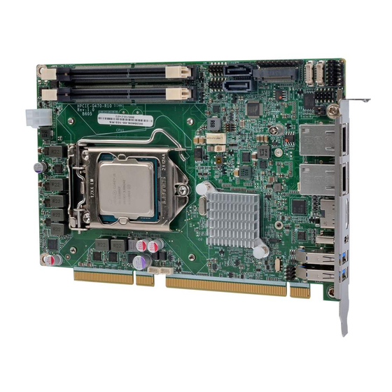
1.1 Introduction Figure 1-1: HPCIE-Q470 The HPCIE-Q470 is a half-size PICMG 1.3 CPU card. It accepts a Socket LGA1200 10th/11th generation Intel® Core™ i9/i7/i5/i3, Pentium® or Celeron® processor and supports two 260-pin 2933 MHz dual-channel DDR4 SO-DIMM, supporting up to 64G. -
Page 13: Features
HPCIE-Q470 Half-size PICMG 1.3 CPU Card 1.2 Features Some of the HPCIE-Q470 motherboard features are listed below: ▪ Half-size PICMG 1.3 CPU card ▪ 10th/11th generation LGA1200 Intel® Core™ i9/i7/i5/i3, Pentium® or Celeron® processor supported ▪ Intel® Q470/Q470E chipset ▪... -
Page 14: Connectors
HPCIE-Q470 Half-size PICMG 1.3 CPU Card 1.3 Connectors The connectors on the HPCIE-Q470 are shown in the figure below. Figure 1-2: Connector Page 14... -
Page 15: Dimensions
HPCIE-Q470 Half-size PICMG 1.3 CPU Card 1.4 Dimensions The main dimensions of the HPCIE-Q470 are shown in the diagram below. Figure 1-3: Dimension (Unit: mm) Page 15... -
Page 16: Data Flow
HPCIE-Q470 Half-size PICMG 1.3 CPU Card 1.5 Data Flow Figure 1-4 shows the data flow between the system chipset, the CPU and other components installed on the motherboard. Figure 1-4: Block Diagram Page 16... -
Page 17: Technical Specifications
HPCIE-Q470 Half-size PICMG 1.3 CPU Card 1.6 Technical Specifications The HPCIE-Q470 technical specifications are listed below. 74 7H Half-Size PICMG 1.3 CPU Card Supports LGA1200 10 Intel® Core™ i9/i7/i5/i3 /Pentium® /Celeron® CPU with Intel® HPCIE-Q470 Q470/Q470E, DDR4 SO-DIMM, HDMI, USB-C, Dual Intel® 2.5GbE, USB 3.2, SATA 6Gb/s, M.2, HD Audio, Intel®... -
Page 18: Table 1-1: Technical Specification
HPCIE-Q470 Half-size PICMG 1.3 CPU Card Chassis Open 1 x Chassis intrusion (1x2 pin) 5V/12V, ATX/AT power supply Power Supply Support AT/ATX mode ErP/EuP compliant Watchdog Timer Software programmable, support 1~255 sec. system reset 3.3V@0.11A, 5V@1.12A, 12V@13.31A, 5VSB@0.15A Power (Intel® Core™ i9-11900K CPU with 4 GB 3200 MHz DDR4 memory) -
Page 19: Packing List
HPCIE-Q470 Half-size PICMG 1.3 CPU Card Chapter Packing List Page 19... -
Page 20: Anti-Static Precautions
Only handle the edges of the PCB: Don't touch the surface of the motherboard. Hold the motherboard by the edges when handling. 2.2 Unpacking Precautions When the HPCIE-Q470 is unpacked, please do the following: ▪ Follow the anti-static guidelines above. -
Page 21: Packing List
Contact the IEI reseller or vendor the HPCIE-Q470 was purchased from or contact an IEI sales representative directly by sending an email to sales@ieiworld.com. 3 26H3 78H The HPCIE-Q470 is shipped with the following components: Quantity Item and Part Number Image HPCIE-Q470 CPU card SATA cable... -
Page 22: Optional Items
HPCIE-Q470 Half-size PICMG 1.3 CPU Card 2.4 Optional Items The following are optional components which may be separately purchased: Item and Part Number Image Dual port USB cable with bracket (P/N: CB-USB02A-RS) SATA power cable (P/N: 32102-000100-200-RS) RS-232/422/485 cable (P/N: 32205-002700-200-RS) -
Page 23: Connectors
HPCIE-Q470 Half-size PICMG 1.3 CPU Card Chapter Connectors Page 23... -
Page 24: Peripheral Interface Connectors
HPCIE-Q470 Half-size PICMG 1.3 CPU Card 3.1 Peripheral Interface Connectors This chapter details all the peripheral interface connectors. 3.1.1 HPCIE-Q470 Layout The figure below shows all the peripheral interface connectors. Figure 3-1: HPCIE-Q470 Layout 3.1.2 Peripheral Interface Connectors The table below lists all the connectors on the board. -
Page 25: External Interface Panel Connectors
HPCIE-Q470 Half-size PICMG 1.3 CPU Card CONNECTOR TYPE LABEL Electronic switch J_ATX_AT1 AT/ATX power mode setting Electronic switch SW_BIOS1_1 BIOS selection switch Electronic switch J_CMOS1 Clear CMOS jumper Flash descriptor security override 3-pin header J_FLASH1 jumper 4-pin connector CPU12V1 ATX CPU 12V power connector... -
Page 26: Internal Peripheral Connectors
HPCIE-Q470 Half-size PICMG 1.3 CPU Card 3.2 Internal Peripheral Connectors The section describes all of the connectors on the HPCIE-Q470. 3.2.1 ATX CPU 12V Power Connector CN Label: CPU12V1 CN Type: 4-pin connector, P=4.2mm CN Location: See Figure 3-2 CN Pinouts:... -
Page 27: Internal Audio Connector For Iei Audio Module
HPCIE-Q470 Half-size PICMG 1.3 CPU Card 3.2.2 Internal Audio Connector for IEI Audio Module CN Label: J_AUDIO1 CN Type: 10-pin Header, P=2.00mm CN Location: See Figure 3-3 CN Pinouts: See Table 3-4 Figure 3-3: Internal Audio Connector Location PIN NO. -
Page 28: Rtc Battery Connector
HPCIE-Q470 Half-size PICMG 1.3 CPU Card 3.2.3 RTC Battery Connector CN Label: BAT1 CN Type: 2-pin Wafer, P=1.25mm CN Location: See Figure 3-4 CN Pinouts: See Table 3-5 Figure 3-4: RTC Battery Connector Location PIN NO. DESCRIPTION PIN NO. DESCRIPTION... -
Page 29: Chassis Instruction Connector
HPCIE-Q470 Half-size PICMG 1.3 CPU Card 3.2.4 Chassis Instruction Connector CN Label: CHASSIS1 CN Type: 2-pin Header, P=2.54mm CN Location: See Figure 3-5 CN Pinouts: See Table 3-6 Figure 3-5: Chassis Instruction Connector Location PIN NO. DESCRIPTION PIN NO. DESCRIPTION +3.3VSB... -
Page 30: Digital Input/Output Connector
HPCIE-Q470 Half-size PICMG 1.3 CPU Card 3.2.5 Digital Input/Output Connector CN Label: DIO1 CN Type: 14-pin Header, P=2.00mm CN Location: See Figure 3-6 CN Pinouts: See Table 3-7 Figure 3-6: Digital Input/Output Connector Location PIN NO. DESCRIPTION PIN NO. DESCRIPTION... -
Page 31: Ec Debug Connector
HPCIE-Q470 Half-size PICMG 1.3 CPU Card 3.2.6 EC Debug Connector CN Label: DBG_SPI1 CN Type: 6-pin Wafer, P=1.25mm CN Location: See Figure 3-7 CN Pinouts: See Table 3-8 Figure 3-7: EC Debug Connector Location PIN NO. DESCRIPTION PIN NO. DESCRIPTION... -
Page 32: Cpu Fan Connector
HPCIE-Q470 Half-size PICMG 1.3 CPU Card 3.2.7 CPU Fan Connector CN Label: CPU_FAN1 CN Type: 4-pin Wafer, P=2.54mm CN Location: See Figure 3-8 CN Pinouts: See Table 3-9 Figure 3-8: CPU Fan Connector Location PIN NO. DESCRIPTION PIN NO. DESCRIPTION... -
Page 33: Flash Spi Rom Connector
HPCIE-Q470 Half-size PICMG 1.3 CPU Card 3.2.8 Flash SPI ROM Connector CN Label: JSPI1 CN Type: 6-pin Wafer, P=1.25mm CN Location: See Figure 3-9 CN Pinouts: See Table 3-10 Figure 3-9: Flash SPI ROM Connector Location DESCRIPTION PIN NO. DESCRIPTION +3.3V... -
Page 34: Flash Ec Rom Connector
HPCIE-Q470 Half-size PICMG 1.3 CPU Card 3.2.9 Flash EC ROM Connector CN Label: JEC1 CN Type: 8-pin Header, P=1.27mm CN Location: See Figure 3-10 CN Pinouts: See Table 3-11 Figure 3-10: Flash EC ROM Connector Location PIN NO. DESCRIPTION PIN NO. DESCRIPTION... -
Page 35: Front Panel Connector
HPCIE-Q470 Half-size PICMG 1.3 CPU Card 3.2.10 Front Panel Connector CN Label: F_PANEL1 CN Type: 10-pin Header, P=2.54mm CN Location: See Figure 3-11 CN Pinouts: See Table 3-12 Figure 3-11: Front Panel Connector Location DESCRIPTI DESCRIP TION PWR_LED+ PWR_BTN+ PWR_LED-... -
Page 36: C Connector
HPCIE-Q470 Half-size PICMG 1.3 CPU Card 3.2.11 I C Connector CN Label: I2C1 CN Type: 4-pin Wafer, P=1.25mm CN Location: See Figure 3-12 CN Pinouts: See Table 3-13 Figure 3-12: I C Connector Location PIN NO. DESCRIPTION PIN NO. DESCRIPTION... -
Page 37: Lan1 Link Led Connector
HPCIE-Q470 Half-size PICMG 1.3 CPU Card 3.2.12 LAN1 Link LED Connector CN Label: LED_LAN1 CN Type: 2-pin Header, P=2.54mm CN Location: See Figure 3-13 CN Pinouts: See Table 3-14 Figure 3-13: LAN1 Link LED Connector Location PIN NO. DESCRIPTION PIN NO. -
Page 38: Lan2 Link Led Connector
HPCIE-Q470 Half-size PICMG 1.3 CPU Card 3.2.13 LAN2 Link LED Connector CN Label: LED_LAN2 CN Type: 2-pin Header, P=2.54mm CN Location: See Figure 3-14 CN Pinouts: See Table 3-15 Figure 3-14: LAN2 Link LED Connector Location PIN NO. DESCRIPTION PIN NO. -
Page 39: Rs-232/422/485 Serial Port Connector
HPCIE-Q470 Half-size PICMG 1.3 CPU Card 3.2.14 RS-232/422/485 Serial Port Connector CN Label: COM1,COM2 CN Type: 10-pin Header, P=2.00mm CN Location: See Figure 3-15 CN Pinouts: See Table 3-16 Figure 3-15: RS-232/422/485 Serial Port Connectors Location PIN NO. DESCRIPTION PIN NO. -
Page 40: Sata 6Gb/S Connector
HPCIE-Q470 Half-size PICMG 1.3 CPU Card Figure 3-16: RS-232/422/485 Pinout 3.2.15 SATA 6Gb/s Connector CN Label: S_ATA1,S_ATA2 CN Type: 7-pin SATA, P=1.27mm CN Location: See Figure 3-17 CN Pinouts: See Table 3-17 Figure 3-17: SATA 6Gb/s Connector Location Page 40... -
Page 41: Smbus Connector
HPCIE-Q470 Half-size PICMG 1.3 CPU Card PIN NO. DESCRIPTION PIN NO. DESCRIPTION SATA_RX ‐ SATA_TX+ SATA RX+ SATA_TX ‐ Table 3-17: SATA 6Gb/s Connector Pinouts 3.2.16 SMBus Connector CN Label: SMB1 CN Type: 4-pin Wafer, P=1.25mm CN Location: See Figure 3-18... -
Page 42: Speaker Connector
HPCIE-Q470 Half-size PICMG 1.3 CPU Card 3.2.17 Speaker Connector CN Label: SPK1 CN Type: 2-pin Wafer, P=1.25mm CN Location: See Figure 3-19 CN Pinouts: See Table 3-19 Figure 3-19: Speaker Connector Location PIN NO. DESCRIPTION PIN NO. DESCRIPTION +V5S PC_BEEP... -
Page 43: Internal Usb 2.0 Connector
HPCIE-Q470 Half-size PICMG 1.3 CPU Card 3.2.18 Internal USB 2.0 Connector CN Label: USB2 CN Type: 8-pin Header, P=2.00mm CN Location: See Figure 3-20 CN Pinouts: See Table 3-20 Figure 3-20: Internal USB 2.0 Connector Location PIN NO. DESCRIPTION PIN NO. DESCRIPTION... -
Page 44: A-Key Slot
HPCIE-Q470 Half-size PICMG 1.3 CPU Card 3.2.19 M.2 A-Key Slot CN Label: M2_A1 CN Type: M.2 A-Key Slot CN Location: See Figure 3-21 CN Pinouts: See Table 3-21 Figure 3-21: M.2 A-Key Slot Location PIN NO. DESCRIPTION PIN NO. DESCRIPTION +3.3V... -
Page 45: Table 3-21: M.2 A-Key Slot Pinouts
HPCIE-Q470 Half-size PICMG 1.3 CPU Card PCIE_TX1+ PCIE_TX1- PCIE_RX1+ PCIE_RX1- PCIE_CLK0+ PCIE_CLK0- PLT_RST CLKREQ0# Pull up +3.3V PCIE_WAKE Pull up +3.3V M2_DAT PCIE_TX2+ M2_CLK PCIE_TX2- PCIE_RX2+ M2_RST PCIE_RX2- CLKREQ0# PCIE_WAKE PCIE_CLK1+ +3.3V PCIE_CLK1- +3.3V Table 3-21: M.2 A-Key Slot Pinouts... -
Page 46: M-Key Slot
HPCIE-Q470 Half-size PICMG 1.3 CPU Card 3.2.20 M.2 M-Key Slot CN Label: M2_M1 CN Type: M.2 M-Key Slot CN Location: See Figure 3-22 CN Pinouts: See Table 3-22 Figure 3-22: M.2 M-Key Slot Location PIN NO. DESCRIPTION PIN NO. DESCRIPTION +3.3V... -
Page 47: Table 3-22: M.2 M-Key Slot Pinouts
HPCIE-Q470 Half-size PICMG 1.3 CPU Card PCIE_TX3- +3.3V +3.3V PCIE_RX2+ +3.3V PCIE_RX2- PCIE_TX2+ PCIE_TX2- PCIE_RX1+ PCIE_RX1- PCIE_TX1+ PCIE_TX1- SATA_SSD_SLP PCIE_RX0+ PCIE_RX0- PCIE_TX0+ PCIE_TX0- M2_RST CLKREQ0# PCIECLK- PCIE_WAKE PCIECLK+ Module Key Module Key Module Key Module Key Module Key Module Key... -
Page 48: External Peripheral Interface Connector Panel
3.3.1 External USB 3.2 Gen 1 Connectors (Type-A) CN Label: CN1, CN2 CN Type: USB Type-A CN Location: See Figure 3-24 CN Pinouts: See Table 3-23 There are two external USB 3.2 Gen 1 connectors on the HPCIE-Q470. Page 48... -
Page 49: External Usb 3.2 Gen 2 Connector (Type-C)
Table 3-23: External USB 3.2 Gen1 Connector (Type-A) Pinouts 3.3.2 External USB 3.2 Gen 2 Connector (Type-C) CN Label: CON1 CN Type: USB Type-C CN Location: See Figure 3-25 CN Pinouts: See Table 3-24 There is one external USB 3.2 Gen 2 connector on the HPCIE-Q470. Page 49... -
Page 50: External Hdmi Connector
HPCIE-Q470 Half-size PICMG 1.3 CPU Card Figure 3-25: External USB 3.2 Gen 2 Connector Location PIN NO. DESCRIPTION PIN NO. DESCRIPTION TX1+ RX1+ TX1- RX1- VBUS VBUS SBU2 SBU1 VCONN VBUS VBUS RX2- TX2- RX2+ TX2+ Table 3-24: External USB 3.2 Gen2 Connetor (Type-C) Pinouts 3.3.3 External HDMI Connector... -
Page 51: Ethernet Connectors
HPCIE-Q470 Half-size PICMG 1.3 CPU Card Figure 3-26: External HDMI Connector Location PIN NO. DESCRIPTION PIN NO. DESCRIPTION HDMI_DATA2 HDMI_CLK# HDMI_DATA2# HDMI_DATA1 HDMI_SCL HDMI_DATA1# HDMI_SDA HDMI_DATA0 HDMI_DATA0# HDMI_HPD HDMI_CLK Table 3-25: External HDMI Connector Pinouts 3.3.4 Ethernet Connectors CN Label:... -
Page 52: Figure 3-27: Ethernet Connectors Location
HPCIE-Q470 Half-size PICMG 1.3 CPU Card Figure 3-27: Ethernet Connectors Location PIN NO. DESCRIPTION PIN NO. DESCRIPTION MDIA3- MDIA1+ MDIA3+ MDIA2+ MDIA2- MDIA0- MDIA1- MDIA0+ Table 3-26: Ethernet Connector Pinouts Figure 3-28: LAN LED Location DESCRIPTION DESCRIPTION on: linked off: 100 Mb/s... -
Page 53: Installation
HPCIE-Q470 Half-size PICMG 1.3 CPU Card Chapter Installation Page 53... -
Page 54: Anti-Static Precautions
Electrostatic discharge (ESD) can cause serious damage to electronic components, including the HPCIE-Q470. Dry climates are especially susceptible to ESD. It is therefore critical that whenever the HPCIE-Q470 or any other electrical component is handled, the following anti-static precautions are strictly adhered to. - Page 55 ▪ Turn all power to the HPCIE-Q470 off: When working with the HPCIE-Q470, make sure that it is disconnected from all power supplies and that no electricity is being fed into the system. Before and during the installation of the HPCIE-Q470, DO NOT: ▪...
-
Page 56: Socket Lga1200 Cpu Installation
HPCIE-Q470 Half-size PICMG 1.3 CPU Card 4.3 Socket LGA1200 CPU Installation WARNING: CPUs are expensive and sensitive components. When installing the CPU please be careful not to damage it in anyway. Make sure the CPU is installed properly and ensure the correct cooling kit is properly installed. -
Page 57: Figure 4-2: Remove Protective Cover
HPCIE-Q470 Half-size PICMG 1.3 CPU Card Figure 4-2: Remove Protective Cover Step 3: Inspect the CPU socket. Make sure there are no bent pins and make sure the socket contacts are free of foreign material. If any debris is found, remove it with compressed air. -
Page 58: Figure 4-3: Insert The Socket Lga1200 Cpu
HPCIE-Q470 Half-size PICMG 1.3 CPU Card Step 7: Insert the CPU. Gently insert the CPU into the socket. If the CPU pins are properly aligned, the CPU should slide into the CPU socket smoothly. See Figure 4-3. Figure 4-3: Insert the Socket LGA1200 CPU Step 8: Close the CPU socket. -
Page 59: Socket Lga1200 Cooling Kit Installation
HPCIE-Q470 Half-size PICMG 1.3 CPU Card Step 9: Connect the 12 V power to the board. Connect the 12 V power from the power supply to the board. 4.4 Socket LGA1200 Cooling Kit Installation WARNING: DO NOT attempt to install a push-pin cooling fan. -
Page 60: Figure 4-5: Cooling Kit Support Bracket
Do not overtighten the screws. Step 5: Connect the fan cable. Connect the cooling kit fan cable to the CPU fan connector on the HPCIE-Q470. Carefully route the cable and avoid heat generating chips and fan blades. Page 60... -
Page 61: So-Dimm Installation
HPCIE-Q470 Half-size PICMG 1.3 CPU Card 4.5 SO-DIMM Installation To install a SO-DIMM, please follow the steps below and refer to Figure 4-6. CAUTION: For dual channel configuration, always install two identical memory modules that feature the same capacity, timings, voltage, number of ranks and the same brand. -
Page 62: Card Installation
HPCIE-Q470 Half-size PICMG 1.3 CPU Card 4.6 M.2 Card Installation The M.2 A-Key card slot allows installation of M.2 A-Key card. To install a M.2 A-Key card, please follow the steps below. Step 1: Locate the M.2 A-Key card slot. See Chapter 3. -
Page 63: System Configuration
HPCIE-Q470 Half-size PICMG 1.3 CPU Card 4.7 System Configuration The system configuration should be performed before installation. 4.7.1 AT/ATX Power Mode Setting The AT and ATX power mode selection is made through the AT/ATX power mode switch which is shown in Figure 4-9. -
Page 64: Clear Cmos Button
HPCIE-Q470 Half-size PICMG 1.3 CPU Card 4.7.2 Clear CMOS Button To reset the BIOS, remove the on-board battery and press the clear CMOS button for three seconds or more. The clear CMOS button location is shown in Figure 4-10. CN Label:... -
Page 65: Bois Selection Switch
HPCIE-Q470 Half-size PICMG 1.3 CPU Card 4.7.3 BOIS Selection Switch The user can select to use either one PCIe x4 slot or four PCIe x1 slots on the backplane via the BIOS switch. Refer to below table for the BIOS switch settings. -
Page 66: Flash Descriptor Security Override Jumper
HPCIE-Q470 Half-size PICMG 1.3 CPU Card PIN NO. DESCRIPTION BIOS1: four PCIe x1 slots Short A - B (default) Short B - C BIOS2: one PCIe x4 slot Table 4-3: BIOS Selection Switch 4.7.4 Flash Descriptor Security Override Jumper The flash descriptor security override jumper (J_FLASH1) allows to enable or disable the ME firmware update. -
Page 67: Usb Power Selection
HPCIE-Q470 Half-size PICMG 1.3 CPU Card To update the ME firmware, please follow the steps below. Step 1: Before turning on the system power, short pin 2-3 of the flash descriptor security override jumper. Step 2: Update the BIOS and ME firmware, and then turn off the system power. -
Page 68: Internal Peripheral Device Connections
This section outlines the installation of peripheral devices to the onboard connectors. 4.8.1 SATA Drive Connection The HPCIE-Q470 is shipped with one SATA drive cables. To connect the SATA drives to the connectors, please follow the steps below. Step 1: Locate the connectors. -
Page 69: Figure 4-14: Sata Power Drive Connection
HPCIE-Q470 Half-size PICMG 1.3 CPU Card Figure 4-14: SATA Power Drive Connection The SATA power cable can be bought from IEI. See Table 2-1: Packing List Optional Items in Section 2.4. Step 5: Configure the Intel® Management Engine BIOS extension (MEBx). To get into the Intel®... - Page 70 HPCIE-Q470 Half-size PICMG 1.3 CPU Card Appendix Regulatory Compliance Page 70...
- Page 71 HPCIE-Q470 Half-size PICMG 1.3 CPU Card DECLARATION OF CONFORMITY This equipment has been tested and found to comply with specifications for CE marking. If the user modifies and/or installs other devices in the equipment, the CE conformity declaration may no longer apply.
- Page 72 HPCIE-Q470 Half-size PICMG 1.3 CPU Card Appendix Product Disposal Page 72...
- Page 73 HPCIE-Q470 Half-size PICMG 1.3 CPU Card CAUTION: Risk of explosion if battery is replaced by an incorrect type. Only certified engineers should replace the on-board battery. Dispose of used batteries according to instructions and local regulations. ▪ Outside the European Union–If you wish to dispose of used electrical and electronic products outside the European Union, please contact your local authority so as to comply with the correct disposal method.
- Page 74 HPCIE-Q470 Half-size PICMG 1.3 CPU Card Appendix Digital I/O Interface Page 74...
- Page 75 HPCIE-Q470 Half-size PICMG 1.3 CPU Card C.1 Introduction The DIO connector on the HPCIE-Q470 is interfaced to GPIO ports on the Super I/O chipset. The digital inputs and digital outputs are generally control signals that control the on/off circuit of external devices or TTL devices. Data can be read or written to the selected address to enable the DIO functions.
- Page 76 HPCIE-Q470 Half-size PICMG 1.3 CPU Card C.2 Assembly Language Sample 1 AX, 6F08H ;setting the digital port as input AL low byte = value AH – 6FH Sub-function: AL – 9 :Set the digital port as OUTPUT :Digital I/O input value C.3 Assembly Language Sample 2...
- Page 77 HPCIE-Q470 Half-size PICMG 1.3 CPU Card Appendix Watchdog Timer Page 77...
- Page 78 HPCIE-Q470 Half-size PICMG 1.3 CPU Card NOTE: The following discussion applies to DOS environment. Contact IEI support or visit the IEI website for specific drivers for other operating systems. The Watchdog Timer is provided to ensure that standalone systems can always recover from catastrophic conditions that cause the CPU to crash.
- Page 79 HPCIE-Q470 Half-size PICMG 1.3 CPU Card NOTE: When exiting a program it is necessary to disable the Watchdog Timer, otherwise the system resets. EXAMPLE PROGRAM: ; INITIAL TIMER PERIOD COUNTER W_LOOP: AX, 6F02H ;setting the time-out value BL, 30 ;time-out value is 48 seconds ;...
- Page 80 HPCIE-Q470 Half-size PICMG 1.3 CPU Card Appendix Error Beep Code Page 80...
- Page 81 HPCIE-Q470 Half-size PICMG 1.3 CPU Card E.1 PEI Beep Codes Number of Beeps Description Memory not Installed Memory was installed twice (InstallPeiMemory routine in PEI Core called twice) Recovery started DXEIPL was not found DXE Core Firmware Volume was not found...
- Page 82 HPCIE-Q470 Half-size PICMG 1.3 CPU Card Appendix Hazardous Materials Disclosure Page 82...
- Page 83 HPCIE-Q470 Half-size PICMG 1.3 CPU Card F.1 RoHS II Directive (2015/863/EU) The details provided in this appendix are to ensure that the product is compliant with the RoHS II Directive (2015/863/EU). The table below acknowledges the presences of small quantities of certain substances in the product, and is applicable to RoHS II Directive (2015/863/EU).
- Page 84 HPCIE-Q470 Half-size PICMG 1.3 CPU Card F.2 China RoHS 此附件旨在确保本产品符合中国 RoHS 标准。以下表格标示此产品中某有毒物质的含量符 合中国 RoHS 标准规定的限量要求。 本产品上会附有”环境友好使用期限”的标签,此期限是估算这些物质”不会有泄漏或突变”的 年限。本产品可能包含有较短的环境友好使用期限的可替换元件,像是电池或灯管,这些元 件将会单独标示出来。 部件名称 有毒有害物质或元素 壳体 显示 印刷电路板 金属螺帽 电缆组装 风扇组装 电力供应组装 电池 O: 表示该有毒有害物质在该部件所有物质材料中的含量均在 SJ/T11364-2014 與 GB/T26572-2011 标准规定的限量要求以下。 X: 表示该有毒有害物质至少在该部件的某一均质材料中的含量超出 SJ/T11364-2014 與 GB/T26572-2011 标准规定的限量要求。...
Need help?
Do you have a question about the HPCIE-Q470 and is the answer not in the manual?
Questions and answers