
Related Manuals for MRC UT-FLU1 Series


Summary of Contents for MRC UT-FLU1 Series
- Page 1 Operation Manual UT-FLU1 SERIES Portable Fluorometer PLEASE READ THIS MANUAL CAREFULLY BEFORE OPERATION Hagavish st. Israel 58817 Tel: 972 3 5595252, Fax: 972 3 5594529 mrc@mrclab.com MRC.4.22...
- Page 2 Foreword Thank you for purchasing our Fluorometer. This user manual describes how the instrument works and the operation guide, please read carefully before operating it. Keep user manual for later use in case you meet with difficulties. Opening Check Please check the instruments as well as all accessories with packing list when you first open it.
- Page 3 Safety and Operating Precautions 1. Safety Information To assure the safe operation, please read this manual carefully before operating. NOTICE: Operation before reading the Manual is forbidden,otherwise instrument in operating may cause injury or electric shock. Read the guidelines and directions below and carry out countermeasures according to them. For Research Use Only.This instruments is not a medical device and is not intended to be used for clinical test.
- Page 4 The Instrument should be put in dry place, less dust, far away from water and high-intensity light. What’s more, the place should be well ventilated, no corrosive gas or strong magnetic interference, far away from heater, stove or any other heat. Power off when you finish your work.
-
Page 5: Table Of Contents
Portable Fluorometer Operation Manual Contents Contents Contents..........................IV Chapter 1 Introduction....................... 1 Chapter 2 Specifications..................... 2 Chapter 3 Instrument Structure..................3 Chapter 4 Installation......................4 4.1 Opening Check......................4 4.2 Installation Conditions....................4 4.3 Installation Steps......................4 4.4 Operating Considerations................... 4 Chapter 5 Software Introduction.................. -
Page 6: Chapter 1 Introduction
Portable Fluorometer Operation Manual Chapter 1 Introduction Chapter 1 Introduction Fluoroimmunoassay (FIA) technology has advantages of high specificity, sensitivity and utility. Therefore, it is used for detecting biological active compounds of low concentration, such as protein (enzyme,receptosome,antibody), nucleic acid, hormone (steroid, thyroid hormones), medicine and microorganism. -
Page 7: Chapter 2 Specifications
Portable Fluorometer Operation Manual Chapter 2 Specifications Chapter 2 Specifications Normal Operating Conditions Ambient temperature:4C 45C Relative humidity:≤70% INPUT Voltage: DC 6~35 V Basic Parameters and Performance Model UT-FLU1A、UT-FLU1B、UT-FLU1C Parameters Light source Monochromatic LED Power < 5 W Linearity R >0.995 Repeatability <1.5%... -
Page 8: Chapter 3 Instrument Structure
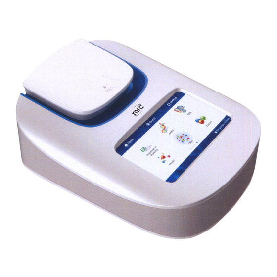
Portable Fluorometer Operation Manual Chapter 3 Instrument Structure Chapter 3 Instrument Structure This chapter introduces the structure of instrument.If it is used for the first time, please read this chapter carefully to make a better preparation. Structure 1: PCR tube base/Sample chamber Display Screen Fig3.1 Structure1... -
Page 9: Chapter 4 Installation
Portable Fluorometer Operation Manual Chapter 4 Installation Chapter 4 Installation Opening Check 4.1 Each UT-FLU1 has been inspected strictly before packing and transportation. Please check again when you receive it.Contact with your local distributor or manufacturer in case of The package inverted or deformated ... - Page 10 Portable Fluorometer Operation Manual Chapter 4 Installation NOTE: Fluorescence PCR tube should be used with tube base together. Sample test steps: 1. Insert PCR tube base first, as fig4.1. 2. Insert fluorescence PCR tube into tube base. 3. Close lid;Click “detecting” for testing. Fluorescence PCR tube PCR tube base Fig4.1 Sample Test Steps...
-
Page 11: Chapter 5 Software Introduction
Portable Fluorometer Operation Manual Chapter 5 Software Introduction Chapter 5 Software Introduction 5.1 Self Testing Instrument will start self testing once powered on. Fig5.1 Starting Interface 5.2 Home Interface Instrument enters into below home interface after self testing finished. Fig5.2 Home Interface There are three function icons on the top of the interface. -
Page 12: Fluorescence Detection
Portable Fluorometer Operation Manual Chapter 5 Software Introduction Report Interface,for looking up all history test datas according to different sorts. System Settings Interface,do a series of normal settings. In the interface of home interface, there are six icons: : Fluorescence detection; : dsDNA detection;... - Page 13 Portable Fluorometer Operation Manual Chapter 5 Software Introduction wavelength ,otherwise you can't get the right result. 460nm Normal Detection Mode. Click the button to enter normal detection mode of fluorescence detection(Fig5.4). Fig5.4 Home>Fluorescenter>Blue 460nm 460nm Kinetic Detection Mode. Click the button to enter 460nm kinetic detection interface as below (Fig5.5): Fig5.5 Home>Fluorescenter>Blue 460nm Kinetic You can set interval time and total run time via click “-”...
-
Page 14: Dsdna Detection
Portable Fluorometer Operation Manual Chapter 5 Software Introduction Fig5.6 Home>Fluorescenter>Blue 460nm Kinetic>Detecting Click to stop kinetic detection; Click to check the kinetic curve (Fig5.7). Fig5.7 Kinetic Detection Curve NOTE: Different channel has different excitation and emission wavelength, see the details in Chapter 2. - Page 15 Portable Fluorometer Operation Manual Chapter 5 Software Introduction Fig5.8 Home>dsDNA Sample Detecting. Choose standard curve to detect fluorescence value and calculate concentration of the sample. NOTE: If there is no standard curve, this item is not available. Standard Curve. Use standard sample to build standard curve for calculating sample concentration.
- Page 16 Portable Fluorometer Operation Manual Chapter 5 Software Introduction Fig5.9 Curve ID Import Curve. Import curve to UT-FLU1 via U flash disk which was exported from UT-FLU1 to the U flash disk before. Click “Im curve” to choose the curve data you (want to import (Fig5.10 Export Curve.
- Page 17 Portable Fluorometer Operation Manual Chapter 5 Software Introduction Fig5.11 Export Curve Fig5.12 Delete Curve 5.2.2.1 Standard Curve Choose a Curve ID or create a new curve to enter “Standard Curve” interface (Fig5.13). In this interface,there are three icons:Parameter, Curve Fitting, View Curve.
- Page 18 Portable Fluorometer Operation Manual Chapter 5 Software Introduction Fig5.13 Home>dsDNA>Standard Curve 1. Parameter Click Parameter and set excitation or emission wavelength and concentration unit of curves(Fig5.14). Fig5.14 Home>dsDNA>Standard Curve>Parameter 2. Curve Fitting Click “Curve Fitting” and standard samples are detected to fit standard curve. You can set concentration of standard sample in this interface,then check the fitting curve,...
- Page 19 Portable Fluorometer Operation Manual Chapter 5 Software Introduction concentration and fluorescence values (Fig5.15). Standard Sample Curve & Quantity Sample Name Sample Concentration Average Fluorescence Value Fluorescence Value One Time > Fig5.15 Home>dsDNA>Standard Curve Curve Fitting NOTE: Fluorescence detection without setting concentration is available while the fluorescence value will not be saved.
- Page 20 Portable Fluorometer Operation Manual Chapter 5 Software Introduction and Quadratic. Detecting the fluorescence valueof sample. Check the previous sample; Check the next sample. Delete the current standard sample data. 3. View Curve View concentration, fluorescence values and equation of current curve (Fig5.17). Fig5.17 Home>dsDNA>Standard Curve>View Curve Click to view excitation or emission wavelength and setting time of the curve .
- Page 21 Portable Fluorometer Operation Manual Chapter 5 Software Introduction Fig5.19 View Curve List 5.2.2.2 Detecting You can use the standard curve to detect the sample. Click “Detecting” to enter the interface (Fig5.20). Original sample concentration Sample concentration in PCR tube Sample volume setting Sample fluorescence Fig5.20 Detecting Interface...
-
Page 22: Report
Portable Fluorometer Operation Manual Chapter 5 Software Introduction Detecting datas will be saved automatically after detecting. You can delete the useless data. It can save 30 datas of each sample detecting at most. Once it is full, the earliest data will be covered. - Page 23 Portable Fluorometer Operation Manual Chapter 5 Software Introduction Fig5.22 Report Interface You can view, print, export and delete the detected data. Click the drop-down list of “Report List” to select the different kinds of test data (Fig5.23). Fig5.23 Report List View the selected results.
-
Page 24: Settings
Portable Fluorometer Operation Manual Chapter 5 Software Introduction NOTE: Once the data is deleted, it can not be recovered. Fig5.24 View Interface 5.4 Settings You can set “Time”, “LCD”, “Print” and “Update” in settings interface(Fig 5.25). Fig5.25 Settings Interface 5.4.1 Time Click “-”... -
Page 25: Lcd
Portable Fluorometer Operation Manual Chapter 5 Software Introduction Fig5.26 Settings>Time Save the date and time you have setted and back to the “Settings” interface. Give up setting and back to the “Settings” interface. 5.4.2 LCD Click “LCD” to set the screen (Fig5.27). Fig5.27 Settings>LCD “Calibration”: According prompt message to calibrate accuracy touch spot of the screen (Fig 5.28). -
Page 26: Print
Portable Fluorometer Operation Manual Chapter 5 Software Introduction Fig5.28 Settings>LCD>Calibration “Brightness”: Click “-” or “+” button to set the screen brightness (Fig5.29). Fig5.29 Settings>LCD>Brightness 5.4.3 Print This instrument is equipped with a thermal printer via “USB” to connect with. Click “Print” to enter the setting interface (Fig5.30). -
Page 27: Updata
Portable Fluorometer Operation Manual Chapter 5 Software Introduction Fig5.30 Settings>Print 5.4.4 Updata Insert the U disk which has stored new version of software and click “OK” button to update the instrument (Fig5.31). You need to restart the instrument to complete update. Fig5.31 Settings>Update... -
Page 28: Chapter 6 Maintenance, Storage And Transportation
Portable Fluorometer Operation Manual Chapter 6 Maintenance, Storage and Transportation Chapter 6 Maintenance, Storage and Transportation Maintenance Keep storage environment dry and clean to prevent from moisture, corrosion, strong electromagnetic interference sources. Instrument already calibrated before delivery. User is not allowed to disassemble the instrument. -
Page 29: Chapter 7 Fault Analysis And Treatment
Portable Fluorometer Operation Manual Chapter 7 Fault Analysis and Treatment Chapter 7 Fault Analysis and Treatment Fault phenomenon Possible Causes Solutions Check the power supply; Instrument can not Power defective Check whether the plug is start loose Power of light source Check the power;... -
Page 30: Chapter 8 Accessories
Portable Fluorometer Operation Manual Chapter 8 Accessories Chapter 8 Accessories Item Unit Remark Power adapter 9V 1.5A 0.5ml PCR tube holder User manual Usb stick...
Need help?
Do you have a question about the UT-FLU1 Series and is the answer not in the manual?
Questions and answers