
Related Manuals for Wahlberg Roll Down

Summary of Contents for Wahlberg Roll Down
- Page 1 Roll Down Item No 249 User Manual WWW.WAHLBERG.DK JENS JUULS VEJ 1 TELEPHONE: +45 86 18 14 20 8260 VIBY EMAIL: sales@wahlberg.dk DENMARK...
-
Page 2: Safety Information
Read this manual before installing, powering or servicing the product; follow the safety precautions listed below and observe all warnings in this manual and printed on the product. If you have questions about how to operate the product, please contact you Wahlberg Motion Design supplier or Wahlberg Motion Design. - Page 3 ............................33 SITE SERVICE ..........................34 AINTENANCE PLAN ..............................34 HECKLIST CON TRUE1 ..................E POWER RROR OOKMARK NOT DEFINED APPENDIX 1 - DIMENSIONS APPENDIX 2 - POWERCON APPENDIX 3 – BLOCK SCHEMATIC ROLL DOWN - CHEAT SHEET 249.805.013 Date: 2021-12-09...
-
Page 4: Technical Specifications
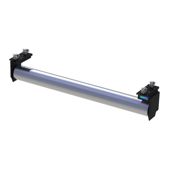
Technical specifications Model: Roll Down Item no.: Dimensions (L×W×H): Motor clamp 190 × 320 × 368 mm (7.5 × 12.6 × 14.5 in) Tube Ø200 × 1500-12000 mm (Ø7.9 × 59.1-472.4 in) Power supply: 208-240V/AC 50-60 Hz Power consumption: 550 W (2,7-2,3A) - Page 5 Drawing Roll Down (249) More detailed drawings and from more angles can be found in Appendix 1 on page 35 249.805.013 Date: 2021-12-09...
-
Page 6: Package Content
Channel 5 is also used for resetting the Roll Down, when powering up if the position was not saved when shut down. On the Roll Down it is also possible to adjust the hard TOP and BOTTOM limits and, in that way, set the absolute span of motion regardless of any DMX control. -
Page 7: Safety Functions
The lighting desk must be programmed according to the manual, so the Roll Down will stop when the speed is put to 0 %. It is also possible for the user to stop the Roll Down by disconnecting it from the mains power. After power failure the start position of the Roll Down may need to be adjusted before the Roll Down can function properly again. - Page 8 Before transport, it is important to roll the fabric of the Roll Down up until the hard TOP limit, and then wrap the remaining fabric around the tube. Fix the fabric with a cable tie or an elastic cord.
-
Page 9: Physical Installation
Physical installation WARNING! The Roll Down must be either fastened to a flat surface such as a roof or clamped to a truss or similar structure in such a way that the mounting clamp points upwards. Do not apply power to the product if it is not securely fastened. -
Page 10: Mounting The Tube
Mounting the tube The Roll Down comes with either a single tube, or two tubes with a splice that allows a total length of the tube up to 12 meters. Single tube: Using a splice: 249.805.013 Date: 2021-12-09... - Page 11 WARNING! The fabric must be mounted on the tube in a way to ensure that the fabric never can damage the Roll Down. WARNING! There should be minimum 1½ round left on the tube when the fabric is rolled all the way out if it is mounted with the rail.
- Page 12 7. Then set the range/soft BOTTOM limit for the desired movement with channel 6. CAUTION! For this specific situation, the range shall be less than 4 meters to ensure 1½ or 2 rounds of fabric is remaining on the tube. 8.
- Page 13 Using the mounting rail The Roll Down has a rail that can be used for mounting the fabric along the entire length of the tube. The fabric is mounted by loosening the Hex screws holding the rail in place. When they are all loose, place the fabric under the rail and tighten the screws again to hold it in place.
-
Page 14: Power Cables And Power Plug
Power cables and power plug The Roll Down requires a power input cable with a Neutrik powerCON TRUE1 NAC3FX-W(-TOP) cable connector for AC mains power input. The cable must rated 20A minimum, have three conductors 1,5mm2 (AWG 16) minimum conductor size and an outer cable diameter of 6-16mm (0.24-0.47 inch). - Page 15 By supplying power to the Roll Down, the display will show a start-up screen sequence showing the model number Followed by a screen showing the software version, e.g. SW 503.003.012 as shown below Then a description of how to enter the menu When it changes to the following, the Roll Down is ready to be operated: 249.805.013...
-
Page 16: Tips For Reliable Data Transmission
Data link A DMX 512 data link is required in order to control the Roll Down via DMX. The Roll Down has 5- pin XLR connectors for DMX data input and output. The pin-out on all connectors is pin 1 = shield, pin 2 = (-), and pin 3 = (+). - Page 17 The DMX control from a lighting desk should always have a set up so there is a button that sets the speed of the Roll Down in operation to 0%. Normally lighting desks have a “blackout” button that sets all intensity channels to 0% and this will also cause the Roll Down to stop when assigned correctly.
-
Page 18: Ready To Use
Menu setting’ on page 19 for guidance on how to navigate the menu. Ready to use When the emergency stop has been enabled, and the Roll Down is connected to power, DMX, and an emergency stop switch, it is ready for use, and can be controlled from the lighting desk. -
Page 19: Menu Setting
Setup WARNING! Read “Safety Information” on page 2 before installing, powering, operating, or servicing the product. WARNING! Only experienced DMX users should operate the product. Contact Wahlberg Motion Design for further information and education on DMX protocol. Menu setting Use the buttons on the display to enter and change menu settings Use the arrows &... -
Page 20: Menu Structure
Menu structure The menu structure is divided into two different areas for safer motor control. Control mode and menu navigation mode. To change between the two push both buttons & hold them for 3 seconds. Control mode The display shows: Shift to next screen by press. -
Page 21: Menu Navigation Mode
Menu navigation mode The display shows: In menu navigate mode, the different parameters can be changed. In menu navigate mode the motor is stopped, and DMX input has no effect, the motor can be moved by the MANUAL RUN - GOING UP/GOING DOWN menu though. Press the arrows to go up or down in the menu choices. -
Page 22: Adjustable Parameters
Save changed value The display shows: Press to change the top line to: Where X is an increasing number from 1 to 20. Then press and hold The top line of the display counts up to 20 then shows OK. The value is now saved in the memory. -
Page 23: Detailed Explanation Of Parameters
This enables/disables the emergency stop from the software. However, to get the full functionality of the emergency stop a wire must be plugged in inside the Roll Down. See section on how to change the wire setting for more details. - Page 24 1,4,5 of the DMX in/out plugs. All values are zero except for the feedback which is located at the DMX address of the device. Meaning if the Roll Down has starting channel 73 then the 16bit feedback will be at channel 73 and 74.
-
Page 25: Dmx Address Setting
DMX ADDRESS setting The DMX address, also known as the start channel, is the first channel used to receive instructions from the controller. For independent control, each product must be assigned to its own control channels. The DMX address is configured in the menu as described in the section above. DMX channel overview Channel Function Description... - Page 26 Adjusting hard limit switches WARNING! There must be at least 1½ round left on the tube when the Roll Down is at the hard BOTTOM limit. Attention! Be careful that the hard TOP limit is not set in a position where the fabric and any counter weight can run into the Roll Down itself, this may damage the Roll Down or fabric.
-
Page 27: Adjusting Procedure
Adjusting procedure 1. Put the Roll Down in manual mode while adjusting the limits. 2. Localise the hard limit switch box, the black box just in front of the fan. 3. Loosen the two screws holding the lid. 4. Loosen the middle screw. -
Page 28: Duty Cycle
Duty cycle The Roll Down should not be operated at a duty cycle higher than 30% for longer periods of time. The duty cycle is the fraction of a period where the motor is active. The duty cycle is commonly expressed as a percentage or a ratio. - Page 29 This difference in speed can be solved by running the Roll Downs with fading positions, like when fading conventional light over time, the position of the Roll Down should be faded from one position to another over a certain amount of time. In that way the Roll Downs will follow the fade- curve, and multiple Roll Downs can follow the same fade curve.
-
Page 30: Led Functions
Reset the top position afterwards. Display says “Not in Pos” The Roll Down cannot move to its position, this usually occurs when the load is high. To solve this, go into the menu and increase the Minimum speed up. Display says “NO MOVEMENT The Roll Down does continuously not measure any movement when trying to DETECTED”... - Page 31 → The motor load is too high INVRTER EEPROM Malfunction in the inverter memory. Power cycle the Roll Down. Unplug the power and wait 30 seconds before applying power again. 9, 64 INVERTER SHORT This is the switch off function due to a short- The inverter was heavily overloaded (also short term).
- Page 32 The shutdown immediately affects the inverter power section. This signal is provided by an orange wire connected to the number 3 connection on the terminal rail in the Roll Down. If this wire is not connected this error will occur. INV SER TIME OUT Shutdown when telegrams fail (serial interface).
-
Page 33: Service And Maintenance
Roll Down. Attention! Signs of malfunction or poor operation should always lead to an inspection of the Roll Down, and the Roll Down should be taken out of operation until the error is eliminated. Parts Only parts ordered at or approved by Wahlberg Motion Design should be used in the Roll Down to ensure product function and stability. -
Page 34: Maintenance Plan
Roll Down showing the date of the inspection, the basis of the inspection and the name of the inspector. Before every use and weekly Every time when rigging the Roll Down, before running the Roll Down – and at least every week when the Roll Down is in use: −... -
Page 35: Appendix 1 - Dimensions
Appendix 1 - Dimensions Roll Down (249) 249.805.013 Date: 2021-12-09... - Page 36 249.805.013 Date: 2021-12-09...
-
Page 37: Appendix 2 - Powercon
Appendix 2 - powerCON 249.805.013 Date: 2021-12-09... - Page 38 249.805.013 Date: 2021-12-09...
-
Page 39: Appendix 3 - Block Schematic
TRUE 1 TRUE 1 Travel range limits Control input Manuel Controller DMX signal control Top hard limit Bottom hard limit Load measuring Motor controller Overload (Electronic) Gear Encoder Block diagram of the control system of the Roll Down. 249.805.013 Date: 2021-12-09... -
Page 40: How To Get Started
DATE: 2021-12-07 How to get started 1. Place / Rig the Roll Down in something high with minimum 2-3 meters clearance below. 2. Connect the mains and emergency switch (if enabled). – The product turns on and the display shows the start-up message.
Need help?
Do you have a question about the Roll Down and is the answer not in the manual?
Questions and answers