Table of Contents
Advertisement
Quick Links
Advertisement
Table of Contents

Subscribe to Our Youtube Channel
Related Manuals for Wahlberg Track Runner Series


Summary of Contents for Wahlberg Track Runner Series
- Page 1 Track Runner Series User Manual Cogwheel Item No. 352.701 (Fast Motor) & 352.702 (Slow Motor) Friction Wheel Item No. 353.701 (Fast Motor) & 353.702 (Slow Motor) WWW.WAHLBERG.DK AXEL GRUHNS VEJ 3 TELEPHONE: +45 86 18 14 20 8270 HØJBJERG EMAIL: sales@wahlberg.dk...
-
Page 2: Safety Information
Read this manual before installing, powering or servicing the product; follow the safety precautions listed below and observe all warnings in this manual and printed on the product. If you have questions about how to operate the product, please contact you Wahlberg Motion Design supplier or Wahlberg Motion Design. -
Page 3: Table Of Contents
PARE PARTS ............................23 SITE SERVICE ..........................23 AINTENANCE PLAN ..............................24 HECKLIST APPENDIX 1 - DIMENSIONS APPENDIX 2 - DIMENSIONS APPENDIX 3 – POWER CONNECTORS APPENDIX 4 - BLOCK DIAGRAM TRACK RUNNER SERIES – CHEAT SHEET 352-353.805.006 Date: 2019-07-02... -
Page 4: Technical Specifications
Technical specifications Model: Track Runner Series Item no.: 352/CW (Cogwheel) and 353/FW (Friction wheel) Dimensions: (L×W×H) without track, switches and antenna etc. 352 (CW) 288 × 223 x 160 mm (11.3 x 8.8 × 6.3 in) 353 (FW) 288 × 251 x 160 mm (11.3 x 9.9 × 6.3 in) Supply range: 115/230 V AC 50-60 Hz. -
Page 5: Drawings
Drawings Track Runner Cogwheel (352) More detailed drawings can be found in Appendix 1 on page 25 352-353.805.006 Date: 2019-07-02... - Page 6 Track Runner Friction Wheel (353) More detailed drawings can be found in Appendix 2 on page 26 352-353.805.006 Date: 2019-07-02...
-
Page 7: Introduction
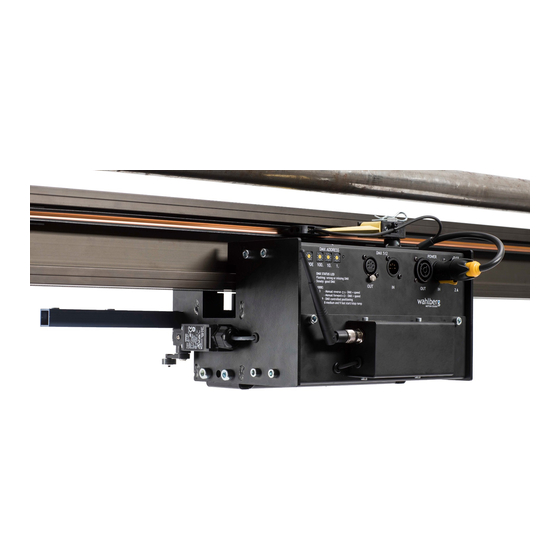
User Manual Cheat sheet Description The Track Runner Series makes your moving heads or scenic elements fly or move smoothly where speed, positing and range all are controlled via DMX directly from a lighting desk using a wireless transmitter (ordered separately). -
Page 8: Area Of Use
Check the Wahlberg Motion Design website at www.wahlberg.dk for the most recent documentation and technical information about the product. Wahlberg user manual revisions are identified by the revision number at the bottom of each page. − Check that the local AC mains power source is within the voltage and frequency ranges specified on the rating label, and/or selected on a voltage/frequency range switch when applicable. -
Page 9: Physical Installation
Accessories The following parts are not included the Track Runner Series and shall be ordered separately. 341.701 1m Track (Rail) [A]*1 340.701 1m Track [A]*1 341.702 2m Track... - Page 10 344.701 End stop set (Right/Left) [E] 344.704 End cover [D] (Cover). 344.720 Cable runner [F] 354 Passive runner 100kg load (220 lb) [H] (End-stop option) 355 Passive runner – Heavy Duty 385 kg (848 344.710 Adjustment tool [I] lb) load [G] for aligning the gear rack across tracks joints...
-
Page 11: Track Assembly Instructions
Table 1 Minimum distance between securement (brackets). The above limitations must be followed and calculated for each customized installation, like for other safety factors or when using a passive runner with heavy loads. Consult your Wahlberg distributor or Wahlberg Motion Design for any questions. -
Page 12: Hard Limit Switches And Passive Runner
Hard limit switches and passive runner In order to avoid collisions each Track Runner will have a hard limit switch on both sides [A]. And when it reaches the end of the track, the rod [B] will activate the on-board limit switch and the unit will stop before it collides. -
Page 13: Ac Power
AC power WARNING! Read “Safety Information” on page 2 before connecting the product to AC mains power. WARNING! For protection from electric shock, do not power the track when not in use or when servicing. Power cables and power plug The track system requires a power input cable with a Neutrik powerCON TRUE1 NAC3FX-W(-TOP) cable connector for AC mains power input, and also the Track Runner requires a NAC3MX-W(- TOP) cable connector for AC output to a powered fixture. -
Page 14: Setup
Mounting on the track The Track Runner Series can be mounted from the left or from the right side of the track, and it is simply done by disconnecting the TRUE1 power input plug [A]. -
Page 15: Mounting The Load
Mounting the load The load on the unit can easily be mounted on the bracket using one or more of the ø12mm holes [A] as shown below. Remove the four M8 bolts [B] to fully access the mounting bracket. WARNING! Maximum bolt length behind the bracket is 40mm WARNING! Minimize... -
Page 16: Radio Control
Radio Control WARNING! This equipment can cause radio interference, make sure this equipment respects all national and local regulations before use. CAUSION: Change or modifications not expressly approved by the party responsible for compliance could void the user’s authority to operate the equipment. The product has a build-in in CRMX wireless DMX to control the operation, and the radio device uses the 2.4 GHz band as accepted in Europe and USA. -
Page 17: Connecting The Wireless Data Link
Connecting the wireless data link To connect the Track Runner to data: 1. Connect the DMX data output from the DMX controller to the Wireless DMX transmitter male 5-pin XLR DMX input connector (DMX 512 IN). 2. Connect the DMX output of the transmitter to the DMX input of other equipment or terminate the link with a 120 Ohm resistor. -
Page 18: Mode Setting
Mode setting The mode switch is found on the front panel left to the DMX address switches and this can be used to select various functions and ramps for normal operation and setup. Mode setting overview MODE Function Description Note None Track Runner is stopped. - Page 19 DMX channel overview channel Function Description Position rough This channel controls the position of the unit, with the speed (DMX channel 3). This rough position works together with the fine position (DMX channel 2). The rough position and the fine position are multiplied in to a 16 bit channel. The rough position is the MSB.
-
Page 20: Setting The Left And Right Positions (Dmx Operation)
Setting the left and right positions (DMX operation) When the unit is ready, the first step is to set the soft-limit left and right positions. See channel description for channel 4, 5 and 6 on the previously page. When the range has been set once on channel 6 it is saved and does not need to be set again unless a new range is needed, or when the unit has been manually operated or removed from the track. -
Page 21: Positioning
Positioning When the unit has been setup and the soft limits is set, it is possible to use it for positioning run. The position is set on the DMX channel 1 and 2, which controls the rough-and fine-position. Where 100 % is the right position(forward) and 0% is the left position(reverse). The positions lamp indicates, by fast flashing, that the unit is going towards the wanted position. -
Page 22: Synchronized Movements Of Multiple Units
Synchronized movements of multiple units If several units are installed to perform synchronized movements, the best result is achieved by using a fading 16 bit position. By nature, there is a slight deviation in performance of the motors, and some motors have a slightly higher maximum speed than others. Like when fading light, the positions of the different units should be faded, and the units will tend to follow that fade. -
Page 23: Service And Maintenance
Spare parts Only parts ordered at or approved by Wahlberg should be used in the product to ensure correct function and stability. Contact Wahlberg to inquire about spare parts. -
Page 24: Checklist
Checklist Use the checklist accordingly; before each use, each month etc. Check Type Result Installed / mounted correct Inspection End stops secured on the track Inspection Load and LEDs visible for the operator Inspection Load mounted safely with or without safety Inspection cable where applicable powerCON TRUE1... -
Page 25: Appendix 1 - Dimensions
Appendix 1 - Dimensions Track Runner CW (Cogwheel) FRONT VIEW FRONT VIEW WITH TRACK TOP VIEW SIDE VIEW 352-353.805.006 Date: 2019-07-02... -
Page 26: Appendix 2 - Dimensions
Appendix 2 - Dimensions Track Runner FW (Friction Wheel) FRONT VIEW FRONT VIEW WITH TRACK TOP VIEW SIDE VIEW 352-353.805.006 Date: 2019-07-02... -
Page 27: Appendix 3 - Power Connectors
Appendix 3 – Power Connectors 352-353.805.006 Date: 2019-07-02... - Page 28 352-353.805.006 Date: 2019-07-02...
-
Page 29: Appendix 4 - Block Diagram
TRUE 1 Current Collectors Power Wireless Wireless AC Mains supply receiver transmitter (External) Microcontroller Control input DMX signal Hard-limit switches Right Left Motor controller Gear Encoder Figure 3 Block diagram of the Track Runner Series control system. 352-353.805.006 Date: 2019-07-02... - Page 30 [This page is intentionally left blank] 352-353.805.006 Date: 2019-07-02...
- Page 31 [This page is intentionally left blank] 352-353.805.006 Date: 2019-07-02...
-
Page 32: Track Runner Series - Cheat Sheet
Track Runner Series – Cheat Sheet MODE Function DMX Ch. Function 0, 1, 6 None, Track Runner is stopped Position rough (Hi of a 16-bit DMX channel) Manual REVERSE slow (no DMX needed) Position fine (Lo of a 16-bit DMX channel)
Need help?
Do you have a question about the Track Runner Series and is the answer not in the manual?
Questions and answers