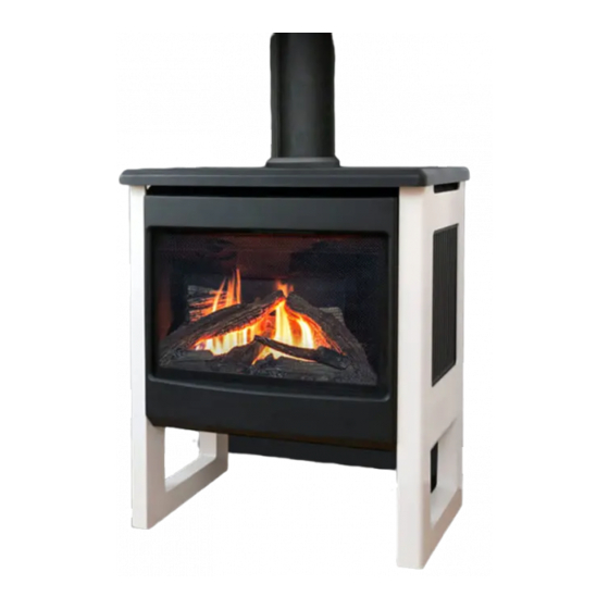
Valor MADRONA MF28JN Installation Manual
Direct vent zero clearance freestanding gas fireplace
Hide thumbs
Also See for MADRONA MF28JN:
- Installation & owner's manual (46 pages) ,
- Installation & owner's manual (54 pages) ,
- Homeowner's manual (24 pages)
Table of Contents
Advertisement
Quick Links
Installation Manual
MADRONA
Installer: Leave this manual with the appliance.
Consumer: Retain this manual for future reference.
WARNING:
FIRE OR EXPLOSION HAZARD
Failure to follow safety warnings
exactly could result in serious
injury, death, or property damage.
Do not store or use gasoline or other
fl ammable vapors and liquids in the
vicinity of this or any other appliance.
WHAT TO DO IF YOU SMELL GAS
Do not try to light any appliance.
▪
DANGER
4005005-15
Hot glass
will cause burns.
Do not touch glass
until cooled.
Never allow children
to touch glass.
Installer: Place model/serial number here.
Do not touch any electrical switch; do
▪
not use any phone in your building.
Leave the building immediately.
▪
Immediately call your gas supplier from
▪
a neighbor's phone. Follow the gas
supplier's instructions.
If you cannot reach your gas supplier,
▪
call the fi re department.
Installation and service must be
performed by a qualifi ed installer, service
agency or the gas supplier.
A barrier designed to reduce
the risk of burns from the hot
viewing glass is provided with this
appliance and must be installed for
the protection of children and
other at-risk individuals.
Direct Vent Zero Clearance
Freestanding Gas Fireplace
natural gas
MF28JN
propane gas MF28JP
Advertisement
Table of Contents

Subscribe to Our Youtube Channel
Related Manuals for Valor MADRONA MF28JN


Summary of Contents for Valor MADRONA MF28JN
- Page 1 Installation Manual MADRONA Direct Vent Zero Clearance Freestanding Gas Fireplace natural gas MF28JN propane gas MF28JP Installer: Place model/serial number here. Installer: Leave this manual with the appliance. Consumer: Retain this manual for future reference. Do not touch any electrical switch; do ▪...
- Page 2 Miles Industries Ltd. grants no warranty, implied or stated, for the installation or maintenance of your heater, and Valor Fireplaces assumes no responsibility for any consequential 190–2255 Dollarton Highway damage(s).
-
Page 3: Table Of Contents
Welcome to Valor ® This appliance has been professionally installed by: Please read this manual BEFORE Dealer Name: ________________________________ installing and operating this Phone:______________________________________ appliance. Stove Safety ............4 Specifi cations ............. 6 Kits & Accessories ..........7 Dimensions & Clearances......... 8 Venting .............. -
Page 4: Stove Safety
Failure to follow these instructions may result in possible fi re hazard and will void the warranty. Replacement manuals are available by contacting the Valor Customer Service at 1-800-468-2567, or by visiting valorfi... - Page 5 Stove Safety Glass window Intended use • This appliance is designed and approved as a supple- mental heater and provides the potential for most WARNING energy conservation when used while attended. The Do not operate this appliance with the use of an alternate primary heat source is advisable. glass front removed, cracked, or broken.
-
Page 6: Specifications
Specifications Approval & Codes Supply Gas This appliance is certified to ANSI Z21.88/CSA 2.33 Heater engine MF28JN is used with natural gas. American National Standard / CSA Standard for Vented Heater engine MF28JP is used with propane gas. Gas Fireplace Heaters for use in Canada and USA, and The supply pressure must be between the limits shown to CGA 2.17-M91 High Altitude Standard in Canada. -
Page 7: Kits & Accessories
Specifications Madrona Stove WARNING There are two types of stove casing for the Madrona MF28J engine, a traditional style available in two colors HOT HEARTH/FLOOR! The hearth or floor and a contemporary style. The stove casings are sold in front of the stove may become very hot separately. -
Page 8: Dimensions & Clearances
Dimensions & Clearances Traditional Cast Stove MFCS01 (black) or Traditional Cast Stove MFCS02 (Majolica brown)— arched or square fronted Suggested gas line 2” (52 mm) 4” access point through wall. minimum (102 mm) Route to avoid optional fan. Ø 6-5/8” venting Mantel / shelf clearances Mantel... - Page 9 Dimensions & Clearances Modern Stove MFCS05 Suggested gas line 1 [26] access point through wall. minimum 4-5/8 [118] Route to avoid optional fan. 10 [254] Ø 6-5/8” venting Mantel / shelf clearances Pipe supplied with engine Mantel 0–1” 2–5” 6–18” 19–24”...
-
Page 10: Venting
Venting Overview Top or Rear Facing Take-Off Framing Vent in Combustible Walls & Ceilings This appliance is supplied with a top facing take-off When penetrating through combustible walls and which may be converted to a rear facing one with no ceilings, frame a minimum of 10 inches x 10 inches extra parts required—see Vent Outlet page 19 for details. -
Page 11: Co-Axial
Venting Co-Axial Typical Co-Axial Venting Components See venting accessories list on pages 33-34 for allowable components. Maximum pipe length: 24” (straight out with snorkel) 14” (45° elbow out with snorkel) Snorkel required (min. 14” high) with horizontal run through the wall (no rise) No more than one 45°... -
Page 12: Venting Chart
Venting Co-Axial Venting Chart Allowable Co-Axial Vent Confi gurations with restrictor positions How to Read the Venting Charts The chart below applies to co-axial roof or wall termination in installations with vertical rise. All rear venting without a vertical rise must be terminated by a snorkel—see page 11. -
Page 13: Venting Diagram
Venting Co-Axial Venting Diagram 5 x 90º ELBOWS MAXIMUM (or equivalent) Roof termination Sidewall 3” min. termination above top of horizontal pipe 1” min. all around 1” min. around vertical pipe bottom & sides of horizontal pipe Sidewall termination Use 658TG or 845TG vent Min. -
Page 14: Restrictors
Venting Co-Axial Restrictors SOME INSTALLATIONS REQUIRE RESTRICTORS. For improved flame picture and performance, this unit is supplied with two different sets of vent restrictors. The level of restriction required depends on the vertical rise in the venting system and, to a lesser degree, the horizontal run and number of elbows. -
Page 15: Horizontal Vent Termination Location
Venting Co-Axial Horizontal Vent Termination Location air ow or a safety hazard. Local codes or regulations Horizontal Vent Termination Location may require greater clearances. • The vent terminal must be located on an outside wall or through the roof. • The vent terminal must not be recessed into a wall or siding. -
Page 16: Vertical Vent Termination
Venting Co-Axial Vertical Vent Termination Overhang should not extend beyond vent if within 48” of Minimum Horizontal Roof Pitch termination cap "H" [feet] overhang Flat to 7/12 Termination Min. 24” Over 7/12 to (unvented soffit) 1.5' 8/12 Vertical Min. 36” Min. -
Page 17: Preparation
Preparation Before Installing Installation Considerations Attention Fan (Blower) Allow for and install electrical wiring if there will be a ONLY qualified licensed or trained personnel should install this appliance. fan (blower) to install. Ask the homeowner if you are not sure. Venting Configuration 1. -
Page 18: Installation
Installation Window & Optional Fan Remove Window Unclip Remote Control Receiver It is easier to remove the window and all the items Under the packed inside of the firebox to make the engine lighter appliance, the for installation. receiver box is 1. -
Page 19: Vent Outlet
Installation Vent Outlet Install Gas Pipe & Connector Convert Vent Outlet (if necessary) The gas pipe, connector, clamp and fixing screw are Rear Vent supplied with the engine. If the appliance is to be vented from the top, it is ready The support bracket for the gas pipe is supplied with for vent installation once the engine is on the casting the stove casing. -
Page 20: Gas Supply
Installation Gas Supply Connect Gas Supply The minimum supply pressure is given on page 6 of this manual. The gas supply inlet connection All piping and connections must be tested for leaks is a 3/8 inch NPT female after installation or servicing. All leaks must be connector. -
Page 21: Fuel Beds
Installation Fuel Beds Traditional Log Set MF28LSK 3. Place the top left log on the pin of the rear log. The bottom of the log rests on the left side and of the Material required front left log just installed. •... - Page 22 Installation Fuel Beds 4. Place the front right log on the burner and slide it to 6. Place the lower end of the center right log onto the the left against the front left log. pin on the front right log. Rest the narrow in the notch into the rear log.
-
Page 23: Driftwood Kit Mf28Dwk
Installation Fuel Beds Driftwood Kit MF28DWK Logs 1. Identify the base log and place it in the cavity of the Material required ceramic platform. The protruding parts of the log in • Driftwood Kit containing: front should rest against the lip of the sheet metal •... - Page 24 Installation Fuel Beds 3. Identify the right side cross log, the longest, and 5. Place the front log inserting its two pins into the place it across the rear log. The narrow end of the two holes at the front of the platform. The ends log rests in a notch of the rear log.
-
Page 25: Splitwood Kit Mf28Swk
Installation Fuel Beds Splitwood Kit MF28SWK Logs 1. Identify the base log and place it in the cavity of the Material required ceramic platform. The front of the log should rest • Splitwood Kit containing: against the lip of the sheet metal support behind •... - Page 26 Installation Fuel Beds 3. Install the center cross log placing its larger end in 5. Place the right-hand cross log resting its wider end the notch of the center log and the notch of the base on the edge of the platform and its narrower end in log.
-
Page 27: Refit & Check Window
• Damage components; • Cause overheating resulting in dangerous conditions. Hot Glass Warning Plate Damages caused by incorrect window installation is not covered by the Valor warranty. -
Page 28: Battery Holder
Installation Battery Holder Install Battery Holder 5. Place the receiver and battery holder as shown un- der the firebox, to the left of the control valve The batteries that power the receiver and handset need (placement may vary with installed options). to be installed prior to pairing and use. -
Page 29: Remote Control Pairing
Installation Remote Control Pairing Synchronize Receiver and Handset The receiver and handset of the remote control system must be initially paired before the first use. 1. If not already done, place a new 9 V alkaline battery in the handset. 2. -
Page 30: Operation Check & Burner Aeration
Installation Operation Check & Burner Aeration Check Operation In some installations, depending of the fuel bed used, the altitude and other considerations, the flame picture Turn the fireplace flame up and down using the remote may be improved by adjusting the aeration. The need control to confirm that the full range of inputs is for adjustment should be determined ony by operating achieved—see Appendix B –... -
Page 31: Barrier Screen & Accessories
Installation Barrier Screen & Accessories Front and Barrier Screen Install the front chosen by the customer for the fireplace. Install as well the barrier screen which is provided with the front. Show the customer how to access the controls when the front is installed and how to remove it. -
Page 32: Wiring Diagram
Wiring Diagram MAN Knob Main Valve Knob Optional 1265WSK Wall Switch Kit Combination Control Valve Interruptor ON/OFF Switch Block Connector Thermocouple yellow Antenna Receiver Battery Holder RESET Button GV60 Wiring Diagram... -
Page 33: Approved Venting Components
Approved Venting Components Approved Direct Vent Suppliers for Valor Models 530 , 534, 650 and MF28 Venting Parts Code / availability by Manufacturer Venting Parts Description Standard Co-axial 46DVA-HC 4DT-HC TM-4HT — — 4DHC round 658DVK2 940160 Deluxe Co-axial —... - Page 34 TM-RHTS 658TG Notes: 1. All listed above co-axial pipes and ttings require Valor 817VAK Adapter Kit to t Valor’s smooth collars (Valor adapter 4DSC-V by American Metal Products may also be used). 2. Follow instructions supplied with each manufacturer’s components.
-
Page 35: Commonwealth Of Massachusetts
Commonwealth of Massachusetts State of Massachusetts Carbon Monoxide 4. INSPECTION. The state or local gas inspector of the Detector/Vent Terminal Signage Requirements side wall horizontally vented gas fueled equipment shall not approve the installation unless, upon inspection, For all side wall horizontally vented gas fueled the inspector observes carbon monoxide detectors and equipment installed in every dwelling, building or signage installed in accordance with the provisions of... -
Page 36: Appendix A - Lighting Instructions Plate
Appendix A – Lighting Instructions Plate FOR YOUR SAFETY, READ BEFORE LIGHTING WARNING : If you do not follow these instructions exactly A. This appliance has a pilot which must be lighted by hand or by remote control. Follow these instructions exactly. To save gas, turn the pilot off when not using the appliance for a prolonged period of time. -
Page 37: Appendix B - Remote Control Operation
Appendix B – Remote Control Operation Radio Frequency Turn Fireplace ON 315 MHz for USA and Canada. Press buttons until you hear a short beep; release buttons. This device complies with Part 15 of the FCC Rules and with Industry Canada license-exempt RSS standard(s). Beeping continues until pilot is lit. - Page 38 Appendix B – Remote Control Operation Setting ºC/24-hr or ºF/12-hr clock Manual Mode M A N In MAN mode, press and hold Manual ame height adjustment. buttons until temperature / clock display changes from Daytime Temperature Mode TEMP When pilot is lit, room temperature °F / 12-hour °C / 24-hour is measured and compared to set...
- Page 39 Appendix B – Remote Control Operation Setting high / low Temperatures Setting Program Timers Setting “DAYTIME” high temperature. You can program two periods of time between 12 am and 11:50 pm in each 24-hour cycle. Default Settings: 23 °C/74 °F TEMP Programs P1 and P2 must be set in the following order Press SET to scroll to...
- Page 40 Appendix B – Remote Control Operation Setting P2 high and low temperature times. Repeat same steps as Setting P1. When all settings are complete, press to save them. Timer Programming Example (default temperatures shown) 6:00 am 8:00 am 4:00 pm 10:00 pm 6:00 am high temp...
-
Page 41: Appendix C - Spare Parts
Appendix C – Spare Parts Description Part. no. Description Part. no. Restrictor 50 (2) 4000949 RH Side Gasket 4000643 Restrictor 75 (2) 4000950 Front Gasket 4000641 Dura-Vent Intake Collar 4000925 LH Side Gasket 4000644 Intake Collar Gasket 4000942 Break-off Olive Nut—Pilot Pipe to Valve 220K913 Exhaust Collar Assembly 4000909... - Page 42 Appendix C – Spare Parts Description Part. no. MF28LSK Splitwood Kit MF28SWK Splitwood Set 4006375 Base Log 4006371 RH Cross Log 4006373 Top Center Log 4006402 Center Log 4006372 LH Cross Log 4006401 Platform 4005385 80 gr Black Embers 4006374 GV60 Valve Repair Kit 4004544 Auxiliary Battery Holder...
- Page 43 Appendix C – Spare Parts Natural gas Propane gas...
Need help?
Do you have a question about the MADRONA MF28JN and is the answer not in the manual?
Questions and answers