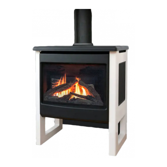
Valor Madrona MF28JN Installation & Owner's Manual
Direct vent gas free standing engine
Hide thumbs
Also See for Madrona MF28JN:
- Installation & owner's manual (46 pages) ,
- Installation manual (43 pages) ,
- Homeowner's manual (24 pages)
Table of Contents
Advertisement
INSTALLATION & OWNER'S MANUAL
Direct Vent Gas Free Standing Engine
MF28JN (natural gas) & MF28JP (propane gas)
CSA approved for use with Valor Free Standing Stoves MFCS01, MFCS02, and MFCS05 ONLY
DANGER
!
A barrier designed to reduce the risk of burns from the hot
viewing glass is provided with this appliance and shall be
installed for the protection of children and other at-risk
individuals.
!
WARNING
FIRE OR EXPLOSION HAZARD
Failure to follow safety warnings exactly
could result in serious injury, death, or
property damage.
— Do not store or use gasoline or other
fl ammable vapors and liquids in the
vicinity of this or any other appliance.
— WHAT TO DO IF YOU SMELL GAS
▪ Do not try to light any appliance.
▪ Do not touch any electrical switch; do
not use any phone in your building.
▪ Leave the building immediately.
▪ Immediately call your gas supplier from
a neighbor's phone. Follow the gas
supplier's instructions.
▪ If you cannot reach your gas supplier,
call the fi re department.
— Installation and service must be
performed by a qualifi ed installer,
service agency or the gas supplier.
4005005-10
©2019, Miles Industries Ltd. All rights reserved.
Madrona
HOT GLASS WILL
CAUSE BURNS.
DO NOT TOUCH GLASS
UNTIL COOLED.
NEVER ALLOW CHILDREN
TO TOUCH GLASS.
Please read this manual
BEFORE
operating this appliance.
INSTALLER
Leave this manual
with the appliance.
CONSUMER
Retain this manual
for future reference.
This manual contains instructions to install the
ENGINE ONLY. A stove casing is REQUIRED
to install the engine. A barrier screen is provided
with the stove casing. Refer to the manual sup-
plied with the stove casing for installation.
This appliance may be installed in an after-
market permanently located, manufactured
(mobile) home where not prohibited by local
codes.
This appliance is only for use with the type
of gas indicated on the rating plate. This
appliance is not convertible for use with
other gases, unless a certifi ed kit is used.
This appliance is a domestic room-heating
appliance. It must not be used for any other
purposes such as drying clothes, etc.
This appliance is suitable for installation in
a bedroom or bed sitting room.
Ce guide est disponible en français sur demande.
installing and
Advertisement
Table of Contents

Subscribe to Our Youtube Channel
Related Manuals for Valor Madrona MF28JN


Summary of Contents for Valor Madrona MF28JN
- Page 1 INSTALLATION & OWNER’S MANUAL Madrona Direct Vent Gas Free Standing Engine MF28JN (natural gas) & MF28JP (propane gas) CSA approved for use with Valor Free Standing Stoves MFCS01, MFCS02, and MFCS05 ONLY DANGER Please read this manual BEFORE installing and operating this appliance.
-
Page 2: Table Of Contents
Detector requirements on page 46. responsibility for any consequential damage(s). Designed and Manufactured by / for Miles Industries Ltd. 190–2255 Dollarton Highway, North Vancouver, BC, CANADA V7H 3B1 Tel. 604-984-3496 Fax 604-984-0246 www.valorfi replaces.com... -
Page 3: Safety And Your Fireplace
Safety and Your Fireplace SAFETY AND YOUR FIREPLACE Read and understand all instructions carefully before Do not use this heater as a temporary source of starting the installation. Failure to follow these instal- heat during construction. lation instructions may result in possible fi re hazard and Due to the high temperature, the appliance should be will void the warranty. - Page 4 Safety and Your Fireplace Read and carefully follow all safety warnings and operating instructions contained in your owner’s manual Replacement manuals are available by contacting the Valor Service Department at 1-800-468-2567 or visit www.valorfi replaces.com. FOLLOW THESE IMPORTANT CHILD SAFETY...
- Page 5 SAFETY AND YOUR FIREPLACE This manual and particularly the preceeding and following pages contain very important information regarding before operating your the safe operation of your fi replace as well as maintenance instructions. Read carefully fi replace and pay special attention to the safety warnings. A heating gas appliance does require safe handling.
-
Page 6: Introduction
Each Valor stove is fully compounds used in the manufacture of the appliance. tested during the production process for your safety They may cause a slight odor and could cause the and comfort. -
Page 7: Operating Your Stove
OWNER’S Operating Your Stove INFORMATION Stove Control Devices In the unlikely event that you cannot turn off your stove with the remote control handset, use the wall switch; There are three ways to control your stove. if the wall switch malfunctions and will not turn off the 1. -
Page 8: Using The Remote Control
OWNER’S Using the Remote Control INFORMATION Radio Frequency Turn Fireplace ON 315 MHz for USA and Canada. Press buttons until you hear a short beep; release buttons. This device complies with Part 15 of the FCC Rules and with Industry Canada license-exempt RSS standard(s). Beeping continues until pilot is lit. - Page 9 OWNER’S Using the Remote Control INFORMATION Setting ºC/24-hr or ºF/12-hr clock Manual Mode M A N In MAN mode, press and hold Manual ame height adjustment. buttons until temperature / clock display changes from Daytime Temperature Mode TEMP When pilot is lit, room temperature °F / 12-hour °C / 24-hour is measured and compared to set...
- Page 10 OWNER’S Using the Remote Control INFORMATION Setting ON / OFF Temperatures Setting Program Timers Setting “DAYTIME” temperature. You can program two periods of time between 12 am and 11:50 pm in each 24-hour cycle. Default Settings: 23 °C/74 °F TEMP Programs P1 and P2 must be set in the following order Press SET to scroll to TEMP...
- Page 11 OWNER’S Using the Remote Control INFORMATION Setting P2 ON and OFF times. Repeat same steps as Setting P1 ON and OFF times. When all settings are complete, press to save them. Timer Programming Example (default temperatures shown) 6:00 am 8:00 am 4:00 pm 10:00 pm 6:00 am...
-
Page 12: Kits & Accessories
OWNER’S Kits & Accessories INFORMATION Required Kits Optional Accessories Information accurate at the time of printing and subject Information accurate at the time of printing and subject to change without notice. to change without notice. Gas Conversion Kits Fuel Beds (choose one) MF28LSK Traditional Log Set MA28INK... -
Page 13: Lighting Instructions
OWNER’S Lighting Instructions INFORMATION FOR YOUR SAFETY, READ BEFORE LIGHTING WARNING : If you do not follow these instructions exactly causing property damage, personal injury or loss of life. . To save gas, turn the pilot off when not using the appliance for a prolonged period of time. WHAT TO DO IF r’s phone. -
Page 14: Servicing & Maintenance
OWNER’S Servicing & Maintenance INFORMATION Servicing Your Fireplace We recommend having your fi replace serviced every year. Contact your supplier quoting the model number. It will be helpful if the appliance’s serial number can also be quoted. These numbers are on the information card. -
Page 15: Cleaning Your Stove
OWNER’S Servicing & Maintenance INFORMATION Cleaning Your Stove Cleaning Your Stove Barrier screens WARNING The barrier screens can be brushed clean. DO NOT TOUCH THE GLASS WHILE IT IS HOT! Stove body Let the stove cool fi rst before cleaning it. The matte cast iron stove body can be brushed clean. - Page 16 Damage caused by incorrect window installa- 5. Re-install the front with barrier screen. tion is not covered by the Valor warranty. WARNING 1. Place it on its frame and hold it in place while F O R S A F E T Y P U R P O S E , ensure the pushing and turning its fastening studs 90 degrees.
-
Page 17: Checking Pilot And Burner Flames
OWNER’S Servicing & Maintenance INFORMATION Checking Pilot and Burner Flames The appliance area must always be kept clear and free from combustible materials, gasoline and other A periodic check of the pilot and burner fl ames should fl ammable vapors and liquids. be made. -
Page 18: Replacing Batteries
OWNER’S Servicing & Maintenance INFORMATION Replacing Batteries 2. Disconnect the battery holder. WARNING DO NOT ATTEMPT TO CHANGE THE BATTER- IES WHILE THE FIREPLACE IS STILL HOT! Let the fi replace cool fi rst before touching it. CAUTION DO NOT USE a screwdriver or other metallic object to remove the batteries from the receiver or the handset! This could cause a short circuit to the receiver. -
Page 19: Specifi Cations
QUALIFIED Specifi cations INSTALLER Approval & Codes Supply Gas This appliance is certifi ed to ANSI Z21.88-2017/CSA Heater engine MF28JN is used with natural gas. 2.33-2017 American National Standard / CSA Standard Heater engine MF28JP is used with propane gas. for Vented Gas Fireplace Heaters for use in Canada The supply pressure must be between the limits and USA, and to CGA 2.17-91 High Altitude Standard in... -
Page 20: Specifi Cations
QUALIFIED Specifi cations INSTALLER Electrical The Madrona stove does not require an electrical power source unless it is fi tted with an optional circulating fan—see page 30. Hearth Requirements This unit is approved for mounting directly on combusti- ble wood fl ooring. If installed directly on carpeting, vinyl or soft combustible fl... -
Page 21: Dimensions & Clearances
QUALIFIED Dimensions & Clearances INSTALLER Traditional Cast Stove MFCS01 (black) or Traditional Cast Stove MFCS02 (Majolica brown)— arched or square fronted Suggested gas line 2” (52 mm) 4” access point through wall. minimum (102 mm) Route to avoid optional fan. Ø... - Page 22 QUALIFIED Dimensions & Clearances INSTALLER Modern Stove MFCS05 Suggested gas line 1” (26 mm) 4-5/8” access point through wall. minimum (118 mm) Route to avoid optional fan. 10” (254 mm) Ø 6-5/8” venting Pipe supplied with engine (see engine manual p. 18) Mantel / shelf clearances Mantel 0–1”...
-
Page 23: Venting
QUALIFIED Venting INSTALLER Top / Rear Outlet Wall Thickness This unit is shipped with a top outlet collar which is The appliance vent is suitable for penetrating a fi eld-convertible to rear outlet—see page 31 for combustible wall assembly up to 14 inches (36 cm) details. - Page 24 QUALIFIED Venting INSTALLER Typical Venting Components See list of approved venting pipes and accessories on pages 44–45. Maximum pipe length: 24” (straight out with snorkel) 14” (45° elbow out with snorkel) Snorkel required (min. 14” high) with horizontal run through the wall (no rise) No more than one 45°...
- Page 25 QUALIFIED Venting INSTALLER How to Read the Venting Chart 4. A maximum of 5 x 90 degrees elbows or equivalent (2 x 45 degrees = 90 degrees) can be used. The chart below applies to top or rear outlet, roof or 5.
- Page 26 QUALIFIED Venting INSTALLER Restrictors SOME INSTALLATIONS REQUIRE RESTRICTORS. The chart on the previous page shows the vent For improved fl ame picture and performance, this unit restrictor required relative to the length of the vent pipe. is supplied with two diff erent sets of vent restrictors. Restrictors are not required for co-linear applications.
- Page 27 QUALIFIED Venting INSTALLER Horizontal Vent Termination Location or a safety hazard. Local codes or regulations may require greater clearances. • The vent terminal must be located on an outside • The vent terminal must not be recessed into a wall wall or through the roof.
-
Page 28: Installation Planning
QUALIFIED Venting INSTALLER Vertical Vent Termination Roof Minimum Pitch "H" (feet) Flat to 7/12 Over 7/12 to 1.5' 8/12 Over 8/12 to 2’ 9/12 Over 9/12 to 2.5’ 10/12 Over 10/12 to 3.25’ 11/12 Over 11/12 to 4’ 12/12 Over 12/12 to 5’... -
Page 29: Remove Window
QUALIFIED Installation INSTALLER Remove Window Unclip Remote Control Receiver It is easier the remove the window and all the items Under the engine, packed inside of the fi rebox to make the engine lighter the receiver box for installation. is clipped 1. -
Page 30: Install Fan (If Used)
QUALIFIED Installation INSTALLER Install Fan (if used) 7. With 2 screws from the burner plate, fi x the fan’s thermoswitch to the underside of the burner plate, If the Circulating Fan Kit (blower) is to be installed, we behind the pilot area. suggest that you do it now. -
Page 31: Convert Vent Outlet (If Necessary)
QUALIFIED Installation INSTALLER Convert Vent Outlet (if necessary) If the appliance is to be vented from the top, it is ready for vent installation once the engine is on the casting base. If the appliance is to be vented from the rear, it must be converted. -
Page 32: Connect Gas Supply
QUALIFIED Installation INSTALLER Connect Gas Supply The minimum supply pressure is given in the Specifi cations section of this manual—page 19. The gas supply inlet connection is a 3/8 inch NPT female connector. All piping and connections must be tested for leaks If a circulating fan or isolating after installation or servicing. -
Page 33: Install Traditional Log Set Mf28Lsk
QUALIFIED Installation INSTALLER Install Traditional Log Set MF28LSK 3. Place the top left log on the pin of the rear log. The bottom of the log rests on the left side end of the Material required front left log just installed. •... - Page 34 QUALIFIED Installation INSTALLER 4. Place the front right log on the burner and slide it to 6. Place the lower end of the center right log onto the the left against the front left log. pin on the front right log. Rest the narrow end in the notch into the rear log.
-
Page 35: Install Driftwood Set Mf28Dwk
QUALIFIED Installation INSTALLER Install Driftwood Set MF28DWK 2. Identify the rear log and place it on top of the base log locating it into the notches on top of the log. Pull Material required the log forward so it is locked in position. •... - Page 36 QUALIFIED Installation INSTALLER 4. Identify the left side cross log which has one pin at one end. Insert the pin in the hole at the front left of the platform and rests the top part of the log into the notch of the rear log as indicated.
-
Page 37: Install Splitwood Kit Mf28Swk
QUALIFIED Installation INSTALLER Install Splitwood Kit MF28SWK Logs 1. Identify the base log and place it in the cavity of the Material required ceramic platform. The front of the log should rest • Splitwood Kit containing: against the lip of the sheet metal support behind the •... - Page 38 QUALIFIED Installation INSTALLER 3. Install the center cross log placing its larger end in 5. Place the right-hand cross log resting it wider end the notch of the center log and the notch of the base on the edge of the platform and its narrower end in log.
-
Page 39: Refi T And Check Window
fi replace, damage components, cause overheating resulting in dangerous conditions. Damage caused by incorrect window installa- tion is not covered by the Valor warranty. To refi t the window: 1. Place it on the fi rebox frame and hold it in place while pushing and turning its fastening studs 90 degrees. -
Page 40: Install Battery Holder
QUALIFIED Installation INSTALLER Install Battery Holder 5. Place the receiver and battery holder as shown under the fi rebox, to the left of the control valve The batteries that power the receiver need to be (placement may vary with installed options). installed and placed prior to synchronization and use. -
Page 41: Synchronize Remote Control
QUALIFIED Installation INSTALLER Synchronize Remote Control 2. Within the subsequent 20 seconds, press the small fl ame button ( ) on the remote handset until you hear The receiver and the handset of the remote control two short beeps confi rming the synchronization is system must be initially synchronized before the fi... -
Page 42: Install Front And Barrier Screen
QUALIFIED Installation INSTALLER Install Front and Barrier Screen When installing the front of the stove make sure you install as well the barrier screen provided with the cast stove body. Show the customer how to remove the barrier screen and how to access the controls. Follow the instructions provided with the stove cast body and leave those instructions behind for the customer’s further reference. -
Page 43: Wiring Diagram
QUALIFIED Wiring Diagram INSTALLER MAN Knob Main Valve Knob Optional 1265WSK Wall Switch Kit Combination Control Valve Interruptor Block Connector Thermocouple Thermal Safety Switch yellow Antenna Receiver Battery Holder RESET Button GV60 Wiring Diagram... -
Page 44: Approved Venting Components
QUALIFIED Approved Venting Components INSTALLER... - Page 45 QUALIFIED Approved Venting Components INSTALLER...
-
Page 46: Commonwealth Of Massachusetts
OWNER’S Commonwealth of Massachusetts INFORMATION State of Massachusetts Carbon Monoxide building at a minimum height of eight (8) feet above grade directly in line with the exhaust vent terminal for Detector/Vent Terminal Signage the horizontally vented gas fueled heating appliance Requirements or equipment. - Page 47 OWNER’S Commonwealth of Massachusetts INFORMATION requirements shall be satisfi ed by the manufacturer: 1. The referenced “special venting system” instructions shall be included with the appliance or equipment installation instructions; and 2. The “special venting systems” shall be Product Approved by the Board, and the instructions for that system shall include a parts list and detailed installation instructions.
-
Page 48: Warranty
Installation and maintenance must be performed by 5. No Other Warranty an authorized and trained dealer in accordance with All obligations to repair this unit are de ned in this warranty. -
Page 49: Spare Parts
OWNER’S Spare Parts INFORMATION Description Part. no. Description Part. no. Restrictor 50 (2) 4000949 Rear Gasket 4000642 Restrictor 75 (2) 4000950 RH Side Gasket 4000643 Dura-Vent Intake Collar 4000925 Front Gasket 4000641 Intake Collar Gasket 4000942 LH Side Gasket 4000644 Exhaust Collar Assembly 4000909 Break-off... - Page 50 OWNER’S Spare Parts INFORMATION Description Part. no. RH Cross Log 4006373 Top Center Log 4006402 Center Log 4006372 LH Cross Log 4006401 Platform 4005385 80 gr Black Embers 4006374 GV60 Valve Repair Kit 4004544 Auxiliary Battery Holder 4006553 Battery Holder Cable 1500 mm 4006552 Natural gas Propane gas...
- Page 51 OWNER’S Spare Parts INFORMATION MF28LSK MF28DWK MF28SWK...
- Page 53 Thank You ... For purchasing a Valor by Miles Industries. Your new radiant gas heater is a technical appliance that must be installed by a qualifi ed installer. Please fi ll in the information below. The information provided will be used for customer records only.
- Page 54 Tape Shut Fold here Postage needed Valor Fireplaces 190 - 2255 Dollarton Highway North Vancouver, BC V7H 3B1 Canada Online Warranty registration at www.valorfi replaces.com Thank you for choosing a Valor Product...
Need help?
Do you have a question about the Madrona MF28JN and is the answer not in the manual?
Questions and answers