Agilent Technologies 7200 Operation Manual
Hide thumbs
Also See for 7200:
- Troubleshooting and maintenance manual (138 pages) ,
- Operation manual (114 pages)

Related Manuals for Agilent Technologies 7200


Summary of Contents for Agilent Technologies 7200
- Page 1 Agilent 7200 Accurate-Mass Quadrupole Time-of-Flight GC/MS System Operation Manual Agilent Technologies...
- Page 2 Notices © Agilent Technologies, Inc. 2012 Warranty Safety Notices No part of this manual may be reproduced in The material contained in this docu- any form or by any means (including elec- ment is provided “as is,” and is sub-...
- Page 3 This manual contains information for operating and maintaining the Agilent 7200 Accurate-Mass Quadrupole Time-of-Flight GC/MS system. “Introduction” Chapter 1 describes general information about the 7200 Q-TOF GC/MS, including a hardware description, and general safety warnings. “Installing GC Columns” Chapter 2 shows you how to prepare a capillary column for use with the MS, install it in the GC oven, and connect it to the MS using the GC/MS interface.
- Page 4 The hardware user information DVDs that ship with your instrument provide an extensive collection of online help, videos, and books for the Agilent 7890A GC, 7200 Q-TOF GC/MS, 7693 ALS, and the 7683B ALS. Included are localized versions of the information you need most, such as: •...
-
Page 5: Table Of Contents
Contents Introduction Abbreviations Used The 7200 Accurate-Mass Quadrupole Time-of-Flight GC/MS System Hardware Description Important Safety Warnings Safety and Regulatory Certifications Intended Use Cleaning/Recycling the Product Liquid Spills Moving or Storing the MS Installing GC Columns Columns To Prepare a Capillary Column for Installation... - Page 6 Controlling Temperatures Controlling Column Flow Controlling Collision Cell Flow Venting the MS Typical Vacuum Pressures in EI Mode To Set Monitors for Temperature and Vacuum Status To Set the MS Analyzer Temperature To Set the GC/MS Interface Temperature from the MassHunter Workstation To Calibrate the Column To Configure the Collision Cell Gas...
- Page 7 The Flow Control Module To Switch from the EI Mode to CI Mode To Operate the Reagent Gas Flow Control Module To Set a Reagent Gas Flow To Perform a CI Autotune Using the Removable Ion Source The Removable Ion Source To Change the Ion Source To Install the RIS Probe Extraction Tool To Remove the Source from the Analyzer Chamber...
- Page 8 Operation Manual...
- Page 9 Safety and Regulatory Certifications Intended Use Cleaning/Recycling the Product Liquid Spills Moving or Storing the MS This section provides general information about the 7200 Accurate-Mass Quadrupole Time-of-Flight (Q-TOF) GC/MS System, including a hardware description, and general safety warnings. Agilent Technologies...
-
Page 10: Introduction
Introduction Abbreviations Used Abbreviations Used The abbreviations in Table 1 are used in discussing this product. They are collected here for convenience. Table 1 Abbreviations Abbreviation Definition Alternating current Automatic liquid sampler Bromofluorobenzene (calibrant) Collision cell Chemical ionization Direct current DFTPP Decafluorotriphenylphosphine (calibrant) Electron impact... - Page 11 Introduction Abbreviations Used Table 1 Abbreviations (continued) Abbreviation Definition Q-TOF Quadrupole time-of-flight Quad Quadrupole mass filter Radio frequency RFPA Radio frequency power amplifier Time-of-flight Torr Unit of pressure, 1 mm Hg Turbo Turbomolecular vacuum pump Operation Manual...
-
Page 12: The 7200 Accurate-Mass Quadrupole Time-Of-Flight Gc/Ms System
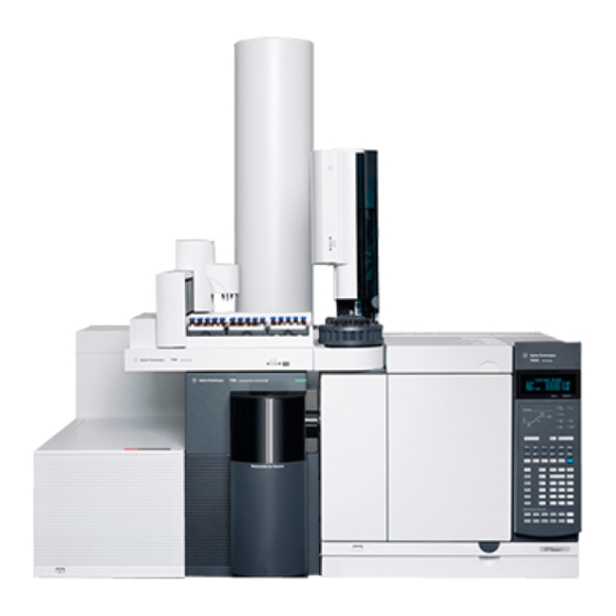
Physical description The 7200 Q-TOF GC/MS is approximately 48 cm high, 71 cm wide, and 89 cm deep excluding the flight tube and RIS handle. The flight tube extends 84 cm up over the top of the instrument. - Page 13 • G3850AA 7200 Q-TOF GC/MS EI RIS Bundle • G3851AA 7200 Q-TOF GC/MS EI/CI RIS Bundle An upgrade kit is available, which allows the user to bring an EI system to an EI/CI system. This kit adds to the 7200 Q-TOF GC/MS: • CI ion source •...
- Page 14 Introduction The 7200 Accurate-Mass Quadrupole Time-of-Flight GC/MS System the ionization volume long enough for the appropriate reactions to occur. The interface has special plumbing for reagent gas. A retractable insulating seal fits onto the tip of the interface and is used for both CI and EI.
-
Page 15: Hardware Description
Introduction Hardware Description Hardware Description Figure 1 is an overview of a typical Agilent 7200 Accurate-Mass Q-TOF GC/MS system. Flight tube ALS tray 7890 GC Q-TOF Lower RIS Upper RIS GC power Oven door MS power cover cover switch latch... -
Page 16: Important Safety Warnings
Introduction Important Safety Warnings Important Safety Warnings There are several important safety notices to always keep in mind when using the instrument. Many internal parts of these instruments carry dangerous voltages If the instrument is connected to a power source, even if the power switch is off, potentially dangerous voltages exist on: •... - Page 17 Introduction Important Safety Warnings Electrostatic discharge is a threat to instrument electronics The printed circuit boards in these instruments can be damaged by electrostatic discharge. Do not touch any of the boards unless it is absolutely necessary. If you must handle them, wear a grounded wrist strap and take other antistatic precautions.
- Page 18 Introduction Important Safety Warnings • Foreline pump • GC/MS transfer line Always cool these areas of the system to room temperature before working on them. They will cool faster if you first set the temperature of the heated zone to room temperature. Turn the zone off after it has reached the setpoint.
- Page 19 Introduction Important Safety Warnings Combustible materials (or flammable/nonflammable wicking WARNI NG material) placed under, over, or around the foreline (roughing) pump constitutes a fire hazard. Keep the pan clean, but do not leave absorbent material such as paper towels in it. Operation Manual...
-
Page 20: Safety And Regulatory Certifications
• AUS/NZ This ISM device complies with Canadian ICES-001. Cet appareil ISM est conforme a la norme NMB—001 du Canada. The 7200 Q-TOF GC/MS is designed and manufactured under a quality system registered to ISO 9001. Information The Agilent Technologies 7200 Accurate-Mass Q-TOF GC/MS... - Page 21 Failure to comply with these precautions violates safety standards of design and the intended use of the instrument. Agilent Technologies assumes no liability for the customer’s failure to comply with these requirements. See accompanying instructions for more information.
- Page 22 4 Make sure that all peripheral devices are also certified. 5 Make sure that appropriate cables are used to connect the device to peripheral equipment. 6 Consult your equipment dealer, Agilent Technologies, or an experienced technician for assistance. Changes or modifications not expressly approved by Agilent Technologies could void the user’s authority to operate the...
-
Page 23: Intended Use
The MS must remain upright at all times; this requires special caution when moving. The MS should not be left vented to atmosphere for long periods. For more information, see “To Move or Store the MS” in the Agilent 7200 Q-TOF GC/MS Troubleshooting and Maintenance Manual. Operation Manual... - Page 24 Introduction Moving or Storing the MS Operation Manual...
-
Page 25: Installing Gc Columns
Agilent 7200 Accurate-Mass Quadrupole Time-of-Flight GC/MS System Operation Manual Installing GC Columns Columns To Prepare a Capillary Column for Installation To Install a Capillary Column in a Split/Splitless Inlet To Condition a Capillary Column To Install a Capillary Column in the GC/MS Interface... -
Page 26: Columns
Installing GC Columns Columns Columns Many types of GC columns can be used with the MS, but there are some restrictions. During tuning or data acquisition the rate of column flow into the MS should not exceed the maximum recommended flow. Therefore, there are limits to column length and flow. - Page 27 Installing GC Columns Columns Conditioning columns Conditioning a column before it is connected to the GC/MS interface is essential. A small portion of the capillary column stationary phase is often carried away by the carrier gas. This is called column bleed.
- Page 28 Installing GC Columns Columns Tips and hints • The column installation procedure for the 7200 Q-TOF GC/MS is different from that for other MSs. Using the procedure from another instrument may not work and may damage the column or the MS.
-
Page 29: To Prepare A Capillary Column For Installation
Installing GC Columns To Prepare a Capillary Column for Installation To Prepare a Capillary Column for Installation Materials needed • Capillary column • Column cutter, ceramic (5181-8836) or diamond (5183-4620) • Ferrules • 0.27 mm id, for 0.10 mm id columns (5062-3518) •... - Page 30 Installing GC Columns To Prepare a Capillary Column for Installation 1 Cool the oven to room temperature. 2 Wearing clean gloves, slide a septum, column nut, and conditioned ferrule onto the free end of the column (Figure 2). The tapered end of the ferrule should point away from the column nut.
-
Page 31: To Install A Capillary Column In A Split/Splitless Inlet
Installing GC Columns To Install a Capillary Column in a Split/Splitless Inlet To Install a Capillary Column in a Split/Splitless Inlet Materials needed • Gloves, clean • Large (8650-0030) • Small (8650-0029) • Metric ruler • Wrench, open-end, 1/4-inch and 5/16-inch (8710-0510) To install columns in other types of inlets, refer to your gas chromatograph user information. - Page 32 Installing GC Columns To Install a Capillary Column in a Split/Splitless Inlet Insulation cup Reducing nut Capillary column 4 to 6 mm Ferrule (inside nut) Inlet column nut Septum Figure 3 Installing a capillary column for a split/splitless inlet Operation Manual...
-
Page 33: To Condition A Capillary Column
Installing GC Columns To Condition a Capillary Column To Condition a Capillary Column Materials needed • Carrier gas, (99.9995% pure or better) • Wrench, open-end, 1/4-inch and 5/16-inch (8710-0510) The use of hydrogen gas is specifically prohibited with this product. WARNI NG The GC operates under high temperatures. - Page 34 Installing GC Columns To Condition a Capillary Column See also For more information about installing a capillary column, refer to Optimizing Splitless Injections on Your GC for High Performance MS Analysis, Agilent Technologies publication number 5988-9944EN. Operation Manual...
-
Page 35: To Install A Capillary Column In The Gc/Ms Interface
Installing GC Columns To Install a Capillary Column in the GC/MS Interface To Install a Capillary Column in the GC/MS Interface This procedure is for the installation of a capillary column directly to the transfer line with a column nut. If you are using the Agilent capillary flow technology Quick Swap accessory, or a Purged Ultimate Union (PUU) see “To Prepare the Column... - Page 36 Installing GC Columns To Install a Capillary Column in the GC/MS Interface Procedure 1 Condition the column. (See “To Condition a Capillary Column” on page 33.) The analyzer, GC/MS interface, and other components in the WARNI NG analyzer chamber operate at very high temperatures. Do not touch any part until you are sure it is cool.
- Page 37 Installing GC Columns To Install a Capillary Column in the GC/MS Interface 9 Slide the column so that the end projects 1–2 mm past the end of the tool. 10 Finger tighten the fitting. 11 Tighten 1/4 to 1/2 turn to fix the ferrule to the column. 12 Slide the column into the GC/MS interface.
-
Page 38: To Prepare The Column Ends For A Cft Fitting
Installing GC Columns To Prepare the Column Ends for a CFT Fitting To Prepare the Column Ends for a CFT Fitting Materials needed • SilTite ferrules: • 0.1- to 0.25-mm columns, pkg of 10 (5188-5361) • 0.32-mm columns, pkg of 10 (5188-5362) •... - Page 39 Installing GC Columns To Prepare the Column Ends for a CFT Fitting The SilTite ferrules are delicate. Follow the instructions in the next C AUTIO N step very carefully to avoid overtightening. 3 Using the wrench and ferrule pre-swaging tool, tighten the nut a little at a time, occasionally checking to see if the ferrule is gripping the tube (see Figure...
- Page 40 Installing GC Columns To Prepare the Column Ends for a CFT Fitting 5 Using a ceramic column cutter, trim the tubing at the small end of the ferrule leaving approximately 0.3 mm of tubing extending beyond the ferrule (Figure It is important that the ceramic column cutter have one side dedicated to only make contact with the column and the other side dedicated to riding on the edge of the metallic SilTite ferrule.
- Page 41 Installing GC Columns To Prepare the Column Ends for a CFT Fitting 6 Check the end of the tube with a magnifier. The end of the tube need not be perfectly square, but should not have cracks which extend under the ferrule. Figure 8 shows a completed tube end.
- Page 42 Installing GC Columns To Prepare the Column Ends for a CFT Fitting Operation Manual...
- Page 43 To Open the Analyzer Cover for Access to the Analyzer Sideplate To Pump Down the MS To Vent the MS This chapter will explain how to perform some routine operating procedures for the 7200 Accurate-Mass Q-TOF GC/MS in EI mode. Agilent Technologies...
-
Page 44: Operating In Electron Impact (Ei) Mode
Your 7200 Q-TOF GC/MS is available in two configurations. The 7200 Q-TOF GC/MS EI RIS Bundle (G3850AA) operates in EI mode with the high sensitivity extractor EI removable ion source (RIS). -
Page 45: The Gc/Ms Interface
Operating in Electron Impact (EI) Mode The GC/MS Interface The GC/MS Interface The GC/MS interface (Figure 10) is a heated conduit into the MS for the capillary column. The interface is bolted onto the right side of the front analyzer chamber and has an O-ring seal. It has a protective insulated cover that should be left in place. - Page 46 Operating in Electron Impact (EI) Mode The GC/MS Interface Spring-loaded tip Column nut seal entrance to ion source GC oven IRM calibrant in Heater sensor assembly Column end protrudes 1 to 2 mm into the ionization chamber. Column not shown Figure 10 The GC/MS interface Operation Manual...
-
Page 47: Before You Turn On The Ms
Operating in Electron Impact (EI) Mode Before You Turn On the MS Before You Turn On the MS Verify the following before you turn on or attempt to operate the • All vacuum seals and fittings must be in place and fastened correctly. -
Page 48: Pumping Down
Operating in Electron Impact (EI) Mode Pumping Down Pumping Down The data system helps you pump down the MS. The process is mostly automated. When you turn on the main power switch (while pressing on the analyzer sideplate), the MS pumps down by itself. -
Page 49: Controlling Collision Cell Flow
Operating in Electron Impact (EI) Mode Controlling Collision Cell Flow The MS can be used to measure actual column flow. You inject a small amount of air or other unretained chemical and time how long it takes to reach the MS. With this time measurement, you can calculate the column flow. -
Page 50: Venting The Ms
Operating in Electron Impact (EI) Mode Venting the MS Venting the MS A program in the data system automates the venting process. It turns off the GC and MS heaters and the turbo pump at the correct time. The MS will be damaged by incorrect venting. A turbo pump will be damaged if it is vented while spinning at more than 50% of its normal operating speed. -
Page 51: Typical Vacuum Pressures In Ei Mode
Operating in Electron Impact (EI) Mode Typical Vacuum Pressures in EI Mode Typical Vacuum Pressures in EI Mode The largest influences on operating pressure in EI mode are the carrier gas (column) and collision cell gas flows. Table 3 lists typical pressures for various helium and nitrogen collision cell gas flows. -
Page 52: To Set Monitors For Temperature And Vacuum Status
Operating in Electron Impact (EI) Mode To Set Monitors for Temperature and Vacuum Status To Set Monitors for Temperature and Vacuum Status A monitor displays the current value of a single instrument parameter. They can be added to the standard instrument control window. - Page 53 Operating in Electron Impact (EI) Mode To Set Monitors for Temperature and Vacuum Status Figure 11 Select Monitors dialog box 3 In the Available Monitors column, select MS Rough Vac and click the Add button to move the selection to the Selected Monitors column.
- Page 54 Operating in Electron Impact (EI) Mode To Set Monitors for Temperature and Vacuum Status 5 In the Available Monitors column, select MS TOF Vac and click the Add button to move the selection to the Selected Monitors column. 6 In the Available Monitors column, select MS Quad Temp and click the Add button to move the selection to the Selected Monitors column.
-
Page 55: To Set The Ms Analyzer Temperature
Operating in Electron Impact (EI) Mode To Set the MS Analyzer Temperature To Set the MS Analyzer Temperature Setpoints for the MS ion source and quad temperatures are stored in the current tune file. When a method is loaded, the setpoints in the tune file associated with that method are downloaded automatically. - Page 56 Operating in Electron Impact (EI) Mode To Set the MS Analyzer Temperature Figure 13 Setting temperatures The GC/MS interface, ion source, and the MS quadrupole heated zones interact. The analyzer heater may not be able to accurately control temperature if the setpoint for one zone is much different from that of an adjacent zone.
-
Page 57: To Set The Gc/Ms Interface Temperature From The Masshunter Workstation
Operating in Electron Impact (EI) Mode To Set the GC/MS Interface Temperature from the MassHunter Workstation To Set the GC/MS Interface Temperature from the MassHunter Workstation You can also use the GC Control panel to perform this task. Procedure 1 Select Instrument > GC Parameters from the Instrument Control panel. -
Page 58: To Calibrate The Column
Operating in Electron Impact (EI) Mode To Calibrate the Column When setting the GC/MS interface temperature, never exceed the C AUTIO N maximum for your column. 3 Check the heater On and enter the setpoint in the Value °C column. The typical setpoint is 280 °C. The limits are 0 °C to 400 °C. - Page 59 Operating in Electron Impact (EI) Mode To Calibrate the Column parameters listed (temperature, inlet and outlet pressures, and gas type) are those used in the method to determine the holdup time. Change any parameters that are different than those used in your method. Figure 15 Calculate Column Length dialog box 11 When the new column length appears, click OK to save the...
-
Page 60: To Configure The Collision Cell Gas
Operating in Electron Impact (EI) Mode To Configure the Collision Cell Gas To Configure the Collision Cell Gas 1 From the MassHunter Data Acquisition Workstation Instrument Control panel, select 2 Select the Modules tab to display the screen. See Figure Figure 16 Configure collision cell gas 3 From the Collision Cell EPC drop-down menu, select N2 as the... -
Page 61: To Set The Collision Cell Gas Flow Rate
Operating in Electron Impact (EI) Mode To Set the Collision Cell Gas Flow Rate To Set the Collision Cell Gas Flow Rate 1 From the MassHunter Data Acquisition Workstation Instrument Control panel, select Instrument > GC Parameters. 2 Click the CFT icon to display the CFT screen. See Figure 3 Select Collision Cell EPC in the description list. -
Page 62: To Autotune The Ms For Ei Mode
Operating in Electron Impact (EI) Mode To Autotune the MS for EI Mode To Autotune the MS for EI Mode The MS can be tuned using the MassHunter Workstation software. Procedure 1 Set the system to the same conditions (GC oven temperature and column flow, and MS analyzer temperature) that will be used for data acquisition. - Page 63 Operating in Electron Impact (EI) Mode To Autotune the MS for EI Mode graph. If specified above, at the completion of the autotune, a Tune Report is printed. To stop the autotune before it completes the automatic parameter selection, click the Abort Tune button. The parameters from the last successful autotune are used.
-
Page 64: To Remove The Upper Ris Cover
Operating in Electron Impact (EI) Mode To Remove the Upper RIS Cover To Remove the Upper RIS Cover The upper RIS cover is in front of the instrument (Figure 19). Remove it to access the latches on the analyzer cover, attach the RIS probe, or access the EI calibration vial. -
Page 65: To Open The Analyzer Cover For Access To The Analyzer Sideplate
Operating in Electron Impact (EI) Mode To Open the Analyzer Cover for Access to the Analyzer Sideplate To Open the Analyzer Cover for Access to the Analyzer Sideplate Open the analyzer cover (Figure 20) to access the analyzer sideplate only. This is necessary during pump down or to access the analyzer sideplate thumbscrews. -
Page 66: To Pump Down The Ms
Operating in Electron Impact (EI) Mode To Pump Down the MS To Pump Down the MS Make sure your MS meets all the conditions listed in the WARNI NG introduction to this chapter before starting up and pumping down the MS. - Page 67 Operating in Electron Impact (EI) Mode To Pump Down the MS 6 Select the MS Tune icon from the Instrument Control panel. 7 Select the Vacuum Control tab. 8 Click the Pumpdown button. Figure 21 Vacuum Control tab Do not turn on any GC heated zones until carrier gas flow is on. Heating C AUTIO N a column with no carrier gas flow will damage the column.
- Page 68 Operating in Electron Impact (EI) Mode To Pump Down the MS 11 After the message Okay to run appears, wait 2 hours for the MS to reach thermal equilibrium. Data acquired before the MS has reached thermal equilibrium may not be reproducible.
-
Page 69: To Vent The Ms
Operating in Electron Impact (EI) Mode To Vent the MS To Vent the MS Procedure 1 Click the MS Tune icon from the Instrument Control panel. 2 Select the Vacuum Control tab. See Figure 3 Set the GC/MS interface heater and the GC oven temperatures to ambient (room temperature). - Page 70 Operating in Electron Impact (EI) Mode To Vent the MS Operation Manual...
- Page 71 To Set a Reagent Gas Flow To Perform a CI Autotune This chapter provides information and instructions for operating the 7200 QTOF GC/MS system in Chemical Ionization (CI) mode. Most of the information in the preceding chapter is also relevant.
-
Page 72: Operating In Chemical Ionization (Ci) Mode
Operating in Chemical Ionization (CI) Mode Setting Up Your MS to Operate in CI Mode Setting Up Your MS to Operate in CI Mode Setting up your MS for operation in CI mode requires special care to avoid contamination and air leaks. •... -
Page 73: The Ci Gc/Ms Interface
Operating in Chemical Ionization (CI) Mode The CI GC/MS Interface The CI GC/MS Interface The CI GC/MS interface (Figure 22) is a heated conduit into the MS for the capillary column. It is bolted onto the right side of the analyzer chamber, with an O-ring seal and has a protective insulated cover which should be left in place. - Page 74 Operating in Chemical Ionization (CI) Mode The CI GC/MS Interface Never exceed the maximum column temperature, either in the GC/MS C AUTIO N interface, the GC oven, or the inlet. The GC/MS interface operates at high temperatures. If you touch it WARNI NG when it is hot, it will burn you.
-
Page 75: Operating The Ci Ms
Operating in Chemical Ionization (CI) Mode Operating the CI MS Operating the CI MS Operating your GC/MS in the CI mode is slightly more complicated than operating in the EI mode. After tuning, gas flow, temperatures (Table 5), and electron energy may need to be optimized for your specific analyte. -
Page 76: High Vacuum Pressure In Ci Mode
Operating in Chemical Ionization (CI) Mode High Vacuum Pressure in CI Mode High Vacuum Pressure in CI Mode The largest influences on operating pressure in CI mode are the reagent and collision cell gas flows. Table 6 lists typical pressures for various reagent gas flows, depending upon the collision cell gas flowrate. - Page 77 Operating in Chemical Ionization (CI) Mode High Vacuum Pressure in CI Mode Table 6 Typical analyzer vacuum with reagent gas flow (continued) Collision cell gas flow on Collision cell gas flow off N2 = 1.5 mL/min MFC (%) Rough vac High vac Rough vac High vac...
-
Page 78: Other Reagent Gases
The principal chemical ionization reactions encountered are described in general in the Agilent 7200 Accurate-Mass Q-TOF GC/MS Concept Guide. If you are not experienced with chemical ionization, we suggest reviewing that material before you proceed. - Page 79 Ammonia tends to break down vacuum pump fluids and seals. Ammonia CI makes more frequent vacuum system maintenance necessary. (See the Agilent 7200 Q-TOF GC/MS Troubleshooting and Maintenance Manual.) When running ammonia for 5 or more hours a day, the foreline pump...
-
Page 80: Ci Autotune
Operating in Chemical Ionization (CI) Mode CI Autotune CI Autotune After the reagent gas flow is set, the lenses and electronics of the MS should be tuned (Table Perfluoro-5,8-dimethyl-3,6,9-trioxidodecane (PFDTD) is used as the calibrant. Instead of flooding the entire vacuum chamber, the PFDTD is introduced directly into the ionization chamber through the GC/MS interface by means of the gas flow control module. - Page 81 Operating in Chemical Ionization (CI) Mode CI Autotune Table 7 CI tune default settings (continued) Parameter Methane Isobutane Ammonia Quad temp 150 °C 150 °C 150 °C 150 °C 150 °C 150 °C 150 °C Interface 280 °C 280 °C 280 °C 280 °C 280 °C...
-
Page 82: The Flow Control Module
Operating in Chemical Ionization (CI) Mode The Flow Control Module The Flow Control Module The CI reagent gas flow control module regulates the flow of reagent gas into the CI GC/MS interface. The flow module consists of a mass flow controller (MFC), gas select valves, CI calibration valve, shutoff valve, control electronics, and plumbing. -
Page 83: To Switch From The Ei Mode To Ci Mode
Operating in Chemical Ionization (CI) Mode To Switch from the EI Mode to CI Mode To Switch from the EI Mode to CI Mode Always verify GC/MS performance in EI before switching to CI C AUTIO N operation. Always wear clean gloves while touching the analyzer or any other C AUTIO N parts that go inside the analyzer chamber. - Page 84 Operating in Chemical Ionization (CI) Mode To Switch from the EI Mode to CI Mode Table 8 Default Tune Control Limits, used by CI autotune only Reagent gas Methane Ammonia Ion polarity Positive Negative Positive Negative Abundance target 1x10 1x10 1x10 Peakwidth target Maximum repeller...
-
Page 85: To Operate The Reagent Gas Flow Control Module
Operating in Chemical Ionization (CI) Mode To Operate the Reagent Gas Flow Control Module To Operate the Reagent Gas Flow Control Module Procedure 1 In Instrument Control panel, select the MS Tune icon to display the GC/Q-TOF Tune dialog box. Select the Manual Tune tab then select the Ion Source tab to display the ion source parameters. - Page 86 Operating in Chemical Ionization (CI) Mode To Operate the Reagent Gas Flow Control Module 2 Use the parameters in the CI Reagent Gas Control area to control reagent gas flow. CI Reagent - Selects the reagent gas from the dropdown menu. CI Gas Flow - Enter percent of maximum volumetric flow for the selected reagent gas.
-
Page 87: To Set A Reagent Gas Flow
Operating in Chemical Ionization (CI) Mode To Set a Reagent Gas Flow To Set a Reagent Gas Flow After the system has been switched from EI to CI mode, or vented for C AUTIO N any other reason, the MS must be baked out for at least 2 hours before tuning. -
Page 88: To Perform A Ci Autotune
Operating in Chemical Ionization (CI) Mode To Perform a CI Autotune To Perform a CI Autotune Always verify MS performance in EI before switching to CI operation. C AUTIO N Avoid tuning more often than is absolutely necessary; this will C AUTIO N minimize PFDTD background noise and help prevent ion source contamination. - Page 89 Operating in Chemical Ionization (CI) Mode To Perform a CI Autotune 8 Select the Tune from default settings check box if you are restarting the system after a system vent, major servicing, or a power outage. If you clear the Tune from default settings box, the Autotune process starts using previous tune values.
- Page 90 Operating in Chemical Ionization (CI) Mode To Perform a CI Autotune Operation Manual...
- Page 91 Agilent 7200 Accurate-Mass Quadrupole Time-of-Flight GC/MS System Operation Manual Using the Removable Ion Source The Removable Ion Source To Change the Ion Source To Install the RIS Probe Extraction Tool To Remove the Source from the Analyzer Chamber To Change the Ion Source on the RIS Probe Extraction Tool...
-
Page 92: Using The Removable Ion Source
The Removable Ion Source The Removable Ion Source The removable ion source (RIS) is a feature of the Agilent 7200 Q-TOF GC/MS that allows changing of the ion source without venting the instrument through the use of the RIS probe extractor tool. - Page 93 Using the Removable Ion Source The Removable Ion Source RIS handle RIS cooling chamber RIS bayonet Figure 24 RIS probe extraction tool Operation Manual...
-
Page 94: To Change The Ion Source
Using the Removable Ion Source To Change the Ion Source To Change the Ion Source The steps necessary for changing the ion source are provided here and also interactively in the MassHunter Workstation software. The process is mostly automated, with the exception of the use of the RIS probe extraction tool to remove and install the ion source. - Page 95 Using the Removable Ion Source To Change the Ion Source 3 Click the Begin button to purge the instrument. 4 When prompted, remove the RIS chamber door and attach the RIS probe extraction tool. See “To Install the RIS Probe Extraction Tool”...
- Page 96 Using the Removable Ion Source To Change the Ion Source 15 Remove the RIS probe extraction tool and replace the RIS chamber cover. See “To Remove the RIS Probe Extraction Tool from the Instrument” on page 104. 16 Click Next to pump down the chamber behind the RIS chamber cover.
-
Page 97: To Install The Ris Probe Extraction Tool
Using the Removable Ion Source To Install the RIS Probe Extraction Tool To Install the RIS Probe Extraction Tool This procedure is part of an automated series of steps controlled by MassHunter. Do not attempt this procedure unless prompted by MassHunter to remove the RIS cover door. Procedure 1 When prompted by MassHunter, remove the upper RIS cover (see... - Page 98 Using the Removable Ion Source To Install the RIS Probe Extraction Tool Figure 26 RIS cover door Figure 27 RIS probe installed Operation Manual...
-
Page 99: To Remove The Source From The Analyzer Chamber
Using the Removable Ion Source To Remove the Source from the Analyzer Chamber To Remove the Source from the Analyzer Chamber This procedure is part of an automated series of steps controlled by MassHunter. Do not attempt this procedure unless prompted by MassHunter. - Page 100 Using the Removable Ion Source To Remove the Source from the Analyzer Chamber 2 Keeping the RIS handle in position, push the RIS handle gently and allow the RIS bayonet to extend into the analyzer chamber. Make sure the RIS handle extends fully, to ensure that the RIS bayonet seats in the holes on the ion source body properly.
-
Page 101: To Change The Ion Source On The Ris Probe Extraction Tool
3 Lock the RIS cooling chamber in the open position by opening it enough to engage the locking pin on the hinge. The 7200 Q-TOF GC/MS operates at high temperatures. Make sure WARN IN G the source is cooled to a safe temperature before attempting to remove it from the RIS cooling chamber. - Page 102 Using the Removable Ion Source To Change the Ion Source on the RIS Probe Extraction Tool 9 Guide the pin on the RIS bayonet into the tracks on the end of the ion source body. 10 While holding the ion source securely, turn the RIS handle counter clockwise so that the alignment guide is in the twelve o’clock position, to lock the ion source securely on the bayonet.
-
Page 103: To Install The Ion Source In The Analyzer Chamber
Using the Removable Ion Source To Install the Ion Source in the Analyzer Chamber To Install the Ion Source in the Analyzer Chamber This procedure is part of an automated series of steps controlled by MassHunter. Do not attempt this procedure unless prompted by MassHunter. -
Page 104: To Remove The Ris Probe Extraction Tool From The Instrument
Tune tab must show the Gate Valve is Open and the RIS vacuum as 0.000 Torr. The 7200 Q-TOF GC/MS operates at high temperatures. Make sure WARN IN G the RIS cooling chamber is at a safe temperature before attempting to remove it from the instrument. - Page 105 Agilent 7200 Accurate-Mass Quadrupole Time-of-Flight GC/MS System Operation Manual General Maintenance Before Starting Maintaining the Vacuum System Maintaining the Analyzer To Disassemble the EI Ion Source To Assemble the EI Ion Source To Disassemble the CI Ion Source To Assemble the CI Ion Source...
-
Page 106: General Maintenance
General Maintenance Before Starting Before Starting You can perform much of the maintenance required by your MS. For your safety, read all of the information in this introduction before performing any maintenance tasks. Scheduled maintenance Common maintenance tasks are listed in Table 9. - Page 107 General Maintenance Before Starting Tools, spare parts, and supplies Some of the required tools, spare parts, and supplies are included in the GC shipping kit, MS shipping kit, or MS tool kit. You must supply others yourself. Each maintenance procedure includes a list of the materials required for that procedure.
- Page 108 General Maintenance Before Starting Dangerous temperatures Many parts in the MS operate at, or reach, temperatures high enough to cause serious burns. These parts include, but are not limited to: • GC/MS interface • Analyzer parts • Vacuum pumps The foreline pump can cause burns if touched when operating. WARNI NG Never touch these parts while your MS is on.
- Page 109 General Maintenance Before Starting An oil mist filter is supplied with the standard foreline pump. This filter stops only pump oil droplets. It does not trap any other chemicals. If you are using toxic solvents or analyzing toxic chemicals, install a hose from the mist filter outlet to the outdoors or into a fume hood vented to the outdoors.
- Page 110 General Maintenance Before Starting Ammonia Ammonia, used as a reagent gas, increases the need for foreline pump maintenance. Ammonia causes foreline pump oil to break down more quickly. Therefore, the oil in the standard foreline vacuum pump must be checked and replaced more frequently. Always purge the MS with methane after using ammonia.
-
Page 111: Maintaining The Vacuum System
Tasks such as replacing an ion vacuum gauge should be performed only when needed by a certified Agilent service personnel. See the Agilent 7200 Accurate-Mass Q-TOF GC/MS Troubleshooting and Maintenance Manual and see the online help in the MassHunter WorkStation software for symptoms that indicate this type of maintenance is required. -
Page 112: Maintaining The Analyzer
MS behavior indicates they are necessary. These tasks include: • Cleaning the ion sources • Replacing filaments The Agilent 7200 Accurate-Mass Q-TOF GC/MS Troubleshooting and Maintenance Manual provides information about symptoms that indicate the need for analyzer maintenance. The troubleshooting material in the online help in the MassHunter Workstation software provides more extensive information. - Page 113 HED ceramic insulator. More information is available If you need more information about the locations or functions of analyzer components, refer to the Agilent 7200 Accurate-Mass Q-TOF GC/MS Concepts Guide. Operation Manual...
-
Page 114: To Disassemble The Ei Ion Source
General Maintenance To Disassemble the EI Ion Source To Disassemble the EI Ion Source Materials needed • Gloves, clean, lint-free • Large (8650-0030) • Small (8650-0029) • Hex ball driver, 1.5 mm (8710-1570) • Hex ball driver, 2.0 mm (8710-1804) •... - Page 115 General Maintenance To Disassemble the EI Ion Source Screws Washers Bayonet mount Repeller insulator Clocking button Repeller cap Repeller Ring heater assembly RIS Extraction source body Filaments Extractor lens insulator RIS Extraction lens Ion focus insulator Ion focus Screws Figure 29 Disassembling the EI ion source Operation Manual...
-
Page 116: To Assemble The Ei Ion Source
General Maintenance To Assemble the EI Ion Source To Assemble the EI Ion Source Materials needed • Gloves, clean, lint-free • Large (8650-0030) • Small (8650-0029) • Hex ball driver, 1.5 mm (8710-1570) • Hex ball driver, 2.0 mm (8710-1804) •... - Page 117 General Maintenance To Assemble the EI Ion Source Screws Washers Bayonet mount Repeller insulator Clocking button Repeller cap Repeller Ring heater assembly RIS Extraction source body Filaments Extractor lens insulator RIS Extraction lens Ion focus insulator Ion focus Screws Figure 30 Assembling the EI source Operation Manual...
-
Page 118: To Disassemble The Ci Ion Source
General Maintenance To Disassemble the CI Ion Source To Disassemble the CI Ion Source Materials needed • Gloves, clean, lint-free • Large (8650-0030) • Small (8650-0029) • Hex ball driver, 1.5 mm (8710-1570) • Hex ball driver, 2.0 mm (8710-1804) •... - Page 119 General Maintenance To Disassemble the CI Ion Source Bayonet mount Clocking button Ring heater / Sensor assembly Repeller RIS CI source body Filament Ion focus insulator Ion focus lens Figure 31 Disassembling the CI ion source Operation Manual...
-
Page 120: To Assemble The Ci Ion Source
General Maintenance To Assemble the CI Ion Source To Assemble the CI Ion Source Materials needed • Gloves, clean, lint-free • Large (8650-0030) • Small (8650-0029) • Hex ball driver, 1.5 mm (8710-1570) • Hex ball driver, 2.0 mm (8710-1804) •... - Page 121 General Maintenance To Assemble the CI Ion Source 7 Place the ion focus assembly on the source body, with the insulator against the source body. Make sure all pins are facing in the same direction. 8 Attach with the two screws. Bayonet mount Clocking button Ring heater / Sensor assembly...
-
Page 122: To Clean The Ion Source
EI ion source. Cleaning of the source is not a scheduled maintenance procedure. The source should be cleaned whenever there are performance anomalies that are associated with a dirty ion source. See the 7200 Q-TOF GC/MS Troubleshooting and Maintenance Manual for symptoms that indicate a dirty ion source. - Page 123 General Maintenance To Clean the Ion Source Preparation 1 Disassemble the ion source. See “To Disassemble the EI Ion Source” on page 114 or “To Disassemble the CI Ion Source” on page 118. 2 Collect the following parts to be cleaned if you are cleaning a high sensitivity extractor EI ion source: (Figure •...
- Page 124 General Maintenance To Clean the Ion Source Ion focus lens Extractor lens Source body Repeller Figure 33 Extractor EI Source parts to be cleaned Ion focus lens Source body Repeller Figure 34 CI Source parts to be cleaned The filaments, source heater assembly, and insulators cannot be CAU TIO N cleaned ultrasonically.
- Page 125 General Maintenance To Clean the Ion Source 4 Abrasively clean the surfaces that contact the sample or ion beam. Use an abrasive slurry of alumina powder and reagent-grade methanol on a cotton swab. Use enough force to remove all discolorations. Polishing the parts is not necessary; small scratches will not harm performance.
-
Page 126: To Remove A Filament
General Maintenance To Remove a Filament To Remove a Filament Materials needed • Gloves, clean, lint-free • Large (8650-0030) • Small (8650-0029) • Hex ball driver, 1.5 mm (8710-1570) • Tweezers (8710-2460) Procedure Always wear clean gloves to prevent contamination when working in C AUTIO N the analyzer chamber. - Page 127 General Maintenance To Remove a Filament Filaments Filament EI Source CI Source Figure 35 Changing the filament Operation Manual...
-
Page 128: To Install A Filament
General Maintenance To Install a Filament To Install a Filament Materials needed • Filament assembly, EI (G3170-60050) • Filament assembly, CI (G1099-80053) • Gloves, clean, lint-free • Large (8650-0030) • Small (8650-0029) • Tweezers (8710-2460) Procedure 1 Remove the old filament. (See “To Remove a Filament”... - Page 132 Agilent Technologies © Agilent Technologies, Inc. Printed in USA, February 2012 *G3850-90005* G3850-90005...