Table of Contents
Advertisement
Advertisement
Table of Contents

Related Manuals for Agilent Technologies 7683


Summary of Contents for Agilent Technologies 7683
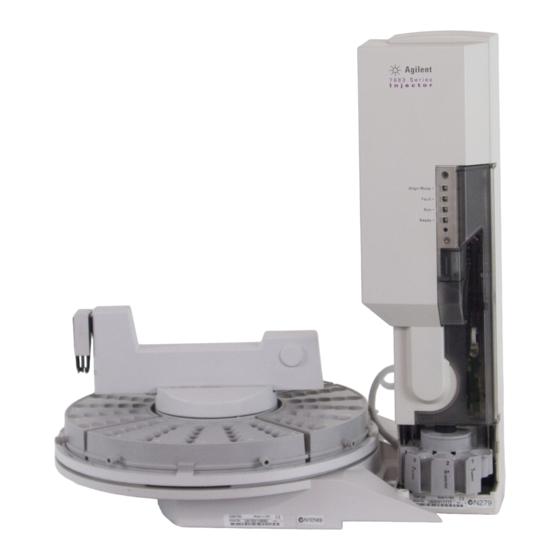
- Page 1 Installation Guide Agilent 7683 Automatic Liquid Sampler...
- Page 2 68 dB(A) during First edition, Jan 2000 Whenever the safety protection short burst injection pulses. CAUTION of the 7683 Automatic Liquid Printed in USA Sampler has been A caution calls attention to a Schalldruckpegel HP® is a registered trademark...
-
Page 3: Table Of Contents
Contents Installation Checklist ................1 Installing the G2614A Tray ..............2 Installing the G2613A Injector .............. 4 Installing the G1926A Bar Code Reader ..........6 Connecting The Cabling ................ 8 Adapting For Cool On-column Injection ........... 10 Configuring Your Gc (6890) ..............12 Making A Trial Run ................ - Page 4 Contents Autoinject Aborted ................ 36 Invalid Sequence ................36 No Injector ..................37 Prerun > 10 Min ................37 Sampler Error ................37...
-
Page 5: Installation Checklist
Installation Checklist Installation Checklist The 7683 Automatic Liquid Sampler consists of the G2612A ALS Interface Board, the G2613A Injector Module, the optional G2614A Tray, and an optional G1926A Bar Code Reader for the tray. The tray and ALS interface board are installed only on the 6890 Plus Gas Chromatograph (GC). -
Page 6: Installing The G2614A Tray
Installation Guide Installing the G2614A Tray Installing the G2614A Tray If you purchased Agilent accessory G2612A separately from your 6890 Plus GC, install it now. Refer to the documentation provided with the accessory for instructions. After it is installed, continue with the steps below to install the optional G2614A Tray. - Page 7 Installation Guide Installing the G2614A Tray Caution Do not move or manipulate the robotic arm or gripper. Moving the arm or gripper back and forth can cause damage. If necessary, rotate the arm assembly a few degrees until there is enough clearance. Align the tray over the 3 holes in the injection port cover and locate in place.
-
Page 8: Installing The G2613A Injector
Installation Guide Installing the G2613A Injector Installing the G2613A Injector Note Do not mount the G2613A Injector on a mounting post for a 7673 Injector. Remove the old post and replace it with the new one. Install the mounting post on the injection port cover in the front or rear location, as desired. - Page 9 Installation Guide Installing the G2613A Injector Front location: Turn the injector so that the turret is facing the front of the GC. Lower the injector until the alignment pin in the base enters the alignment hole in the injection port cover. Back location: Turn the injector so the turret faces the left side of the GC.
-
Page 10: Installing The G1926A Bar Code Reader
Installation Guide Installing the G1926A Bar Code Reader Installing the G1926A Bar Code Reader Install the G1926A Bar Code Reader support bracket under the front of the tray as shown below. Leave the screws slightly loose. You will tighten them later. - Page 11 Installation Guide Installing the G1926A Bar Code Reader Connect the Bar Code Reader cable to the Bar Code Reader connection on the tray. Connect Bar Code Reader Figure 6 Connecting the Bar Code Reader Slide the support bracket towards or away from the tray until the top of the bar code reader is parallel with the tray surface.
-
Page 12: Connecting The Cabling
G2614-60610, to connect the tray to the use GC. See Figure 7 or Figure 8. G2614A Tray G2613A G2613A Injector Injector (Front) (Back) 6890 Plus GC Tray cable Injector cables Figure 7 7683 Automatic Liquid Sampler cabling for 6890 Plus... - Page 13 Connect to top connector only Figure 8 7683 Automatic Liquid Sampler cabling for 6850 When the cables are connected, turn on the GC power. The tray will beep twice. After the start-up process ends, the Ready light on the injector tower should be on.
-
Page 14: Adapting For Cool On-Column Injection
Adapting For Cool On-column Injection Adapting For Cool On-column Injection The 7683 Automatic Liquid Sampler can be adapted to inject samples directly onto 250- µ m, 320- µ m, and 530- µ m columns in the 6890 with cool-on-column inlet. - Page 15 Installation Guide Adapting For Cool On-column Injection 250- µ m/320- µ m 530- µ m (standard) (Agilent accessory 18599T) Figure 9 Needle support assemblies If necessary, reinstall the injector onto the GC. Install the syringe. See your Operation Guide. Rotate the turret clockwise until it stops, then verify the installation by manually sliding the syringe carriage down until the needle enters the inlet.
-
Page 16: Configuring Your Gc (6890)
Installation Guide Configuring Your GC (6890) Configuring Your GC (6890) When installation is complete, configure your 6890 GC for use with the 7683 Automatic Liquid Sampler. Refer to the section on injector configuration in your GC Operating Manual for instructions to set the following: •... -
Page 17: Making A Trial Run
Installation Guide Making A Trial Run Making A Trial Run Once installation and configuration are complete, make a quick injection using the sampler to verify that it works properly. Install an empty syringe in the injector. Place empty bottles in the Solvent A and Waste A turret positions. Place an empty capped sample vial in the tray 1 position (or the turret sample 1 position, if not using the tray). - Page 18 Installation Guide Making A Trial Run Store, load, then run the sequence. • If there are no faults, the injector will make 1 “injection” from the first vial position. • If any faults occur, see Faults on page 26, Error Messages on page 29, Correcting Syringe Problems on page 24, or Correcting Sample Vial Delivery Problems on page 25.
-
Page 19: Maintenance
7683. The maintenance interval varies with the use of the instrument. Caution Do not use any lubricants on the 7683 Automatic Liquid Sampler. They may effect the chemical performance of the GC and damage the instrument. On an occasional basis: Clean the surface of the tray arm, gripper, gripper jaws, and tray quadrants. -
Page 20: Removing The Turret
Installation Guide Removing The Turret Removing The Turret If you need to remove or replace your turret, use the following instructions for proper replacement. For a 6890 GC with a tray only: • Disable the tray if you are changing from the three sample position turret to an eight sample position turret. -
Page 21: Turret Alignment
Installation Guide Turret Alignment Note For increased accuracy of the needle sampling depth, perform the turret alignment procedure each time the turret is changed. See Turret Alignment on page 17. Knurled nut Alignment arrow Motor hub Turret Stripper arm Figure 10 Turret removal Turret Alignment If you changed turrets in the injector and desire increased needle sampling depth accuracy, or if the Align Mode light is on, perform this alignment procedure. - Page 22 Installation Guide Turret Alignment Use a pen to press the recessed alignment button above the indicator lights, then close the door. See Figure 11. Alignment button Align Mode Fault Ready Figure 11 Aligning the turret The injector goes through the following steps: •...
-
Page 23: Replacing The Needle Support Assembly
Installation Guide Replacing The Needle Support Assembly Replacing The Needle Support Assembly Use the standard needle support assembly for all injections except cool on- column injections with a 250- µ m or 320- µ m column. For these injections, you must change the needle support assembly to Agilent accessory 18599T. - Page 24 Installation Guide Replacing The Needle Support Assembly Guide Plunger carrier loop Syringe carriage tracks Slide Bearing clip Bearing Syringe carriage Figure 13 Removing the needle support assembly With your finger under the shaft near the bearing on the needle support assembly, pull gently to release the bearing from the bearing clip in the syringe carriage.
- Page 25 Installation Guide Replacing The Needle Support Assembly To reinstall the needle support assembly, hold it in your right hand and insert the upper end of the rod into the plastic guide to the right of the plunger carrier loop. Turn the needle support assembly so that the flat surface of the slide glides up and down the syringe carriage tracks as shown in Figure 14.
-
Page 26: Replacing The Needle Guide In The Needle Support Foot
Installation Guide Replacing The Needle Guide In The Needle Support Foot Caution Be careful not to bend the needle during installation. Caution Do not operate the injector without a syringe in place because the free swinging syringe latch may interfere with the motor. 10. - Page 27 Installation Guide Replacing The Needle Guide In The Needle Support Foot Screw Metal plate Needle guide Figure 15 Needle support foot (250/320- µ m assembly shown)
-
Page 28: Correcting Syringe Problems
Installation Guide Correcting Syringe Problems Correcting Syringe Problems WARNING When troubleshooting the injector, keep your hands away from the syringe needle. The needle is sharp and may contain hazardous chemicals. Several things can cause syringe needles to bend. When you find one, check for the following conditions before installing a replacement. -
Page 29: Correcting Sample Vial Delivery Problems
Installation Guide Correcting Sample Vial Delivery Problems Correcting Sample Vial Delivery Problems When you find a mishandled sample vial, check: Are there folds or wrinkles in the crimp cap, especially near the neck of the sample vial? For more information, see your Operation Guide and your Sampling Techniques Handbook. -
Page 30: Faults
Installation Guide Faults Faults Four lights on the injector indicate its status. During normal operation, the Ready light is on. If the injector is busy, the Run light is on. If another combination of lights are on, an error has occurred. Use the following instructions to try to solve the problem before obtaining Agilent service. -
Page 31: No Light Is On
Installation Guide Faults No Light Is On Probable causes • The line voltage to the GC is off. • The injector cable or connection to the GC is bad. • Your GC requires service. Suggested actions Verify the injector is properly connected to the GC. Check the power source for your GC. -
Page 32: Align Mode Light Is On
Installation Guide Faults Align Mode Light Is On Probable causes • The turret is not properly installed. • The type of turret was changed while the power was on. • The system was not initialized. • There is an injector memory error. Suggested action Verify the turret is properly installed. -
Page 33: Error Messages
Installation Guide Error Messages Error Messages Below is a table of sampler error messages reported on the 6850 and 6890 Plus GC’s. If you receive an error message that is not shown below, record it. Then, make sure that your GC is properly configured and that your sample vials and equipment match your method and/or sequence. -
Page 34: Bottle In Gripper
Installation Guide Error Messages Bottle In Gripper Probable cause The sample vial was not delivered properly and stayed in the tray gripper. Suggested actions Remove the vial and return it to its position in the tray. Ensure that the tray quadrants are snapped into place. Ensure that the injector is plugged into the correct connector on the back of the 6890 GC and is configured properly. -
Page 35: Front (Or Back) Injector Incomplete Injection
Installation Guide Error Messages Front (Or Back) Injector Incomplete Injection Probable causes • The syringe needle is bent. • The plunger or syringe carriage is operating incorrectly during injection. Suggested actions See Correcting Syringe Problems on page 24. Remove the syringe from the injector, and check the plunger for stickiness or binding. -
Page 36: Front (Or Back) Plunger Error
Installation Guide Error Messages Front (Or Back) Plunger Error Probable causes • The syringe plunger is sticking, or not securely connected to the plunger carrier. • The plunger solenoid is binding. • The plunger carrier encoder is inoperable. Suggested actions Remove the syringe, and check it for plunger stickiness or binding. -
Page 37: Front (Or Back) Turret Error
Installation Guide Error Messages Restart the sequence. If the error occurs again, obtain Agilent service. Front (Or Back) Turret Error Probable causes • Something has interfered with the turret rotation. • The turret motor/encoder assembly is inoperable. • The turret type was changed while the power was on and the turret alignment procedure was not performed. -
Page 38: Injector Offline
Installation Guide Error Messages Check your method to make sure it uses the appropriate injector location. If the error remains, obtain Agilent service. Injector Offline Probable causes • There is a board failure in the injector or GC. • The injector cable is bad or not connected. •... -
Page 39: No Bottle In Gripper
Installation Guide Error Messages No Bottle In Gripper Probable causes • The sample vial was not found by the gripper. • The gripper could not grasp the vial. • The vial was dropped during transfer to or from the turret. •... -
Page 40: Tray Offline
Installation Guide Error Messages Tray Offline Probable causes • There is a board failure in the tray or GC. • The tray cable is bad or not connected. • There is a cable failure in the GC. Suggested actions Make sure that the tray to GC cable connection is secure. Replace the tray cable. -
Page 41: No Injector
Installation Guide Error Messages No Injector Probable causes • The cabling connection to the GC became loose during a run. • An injector board or GC board failed during a run. Suggested actions Make sure that the connection to the GC is secure. If the error remains, obtain Agilent service. - Page 42 Installation Guide Error Messages...