Agilent Technologies 7200 Operation Manual
Accurate-mass quadrupole time-of-flight gc/ms system
Hide thumbs
Also See for 7200:
- Troubleshooting and maintenance manual (138 pages) ,
- Operation manual (132 pages)

Related Manuals for Agilent Technologies 7200


Summary of Contents for Agilent Technologies 7200
- Page 1 Agilent 7200 Accurate-Mass Quadrupole Time-of-Flight GC/MS System Operation Manual Agilent Technologies...
- Page 2 Notices © Agilent Technologies, Inc. 2012, 2014 Warranty Safety Notices No part of this manual may be reproduced in The material contained in this docu- any form or by any means (including elec- ment is provided “as is,” and is sub-...
- Page 3 This manual contains information for operating and maintaining the Agilent 7200 Accurate-Mass Quadrupole Time-of-Flight GC/MS system. “Introduction” Chapter 1 describes general information about the 7200 Q-TOF GC/MS, including a hardware description, and general safety warnings. “Installing GC Columns” Chapter 2 shows you how to prepare a capillary column for use with the MS, install it in the GC oven, and connect it to the MS using the GC/MS interface.
- Page 4 This can be installed by anyone who has authority to copy information onto the receiving computer. See the Agilent 7200 Accurate Mass Q-TOF GC/MS System Quick Start document (G6845-90014) for more details on how to install this information on your computer.
-
Page 5: Table Of Contents
Contents Introduction Abbreviations Used The 7200 Accurate-Mass Quadrupole Time-of-Flight GC/MS System Hardware Description Important Safety Warnings Safety and Regulatory Certifications Intended Use Cleaning/Recycling the Product Liquid Spills Moving or Storing the MS Installing GC Columns Columns To Install a Capillary Column in a Split/Splitless Inlet... - Page 6 Setting Up Your MS to Operate in CI Mode The GC/MS Interface Operating the CI MS High Vacuum Pressure in CI Mode Other Reagent Gases CI Autotune The Flow Control Module To Switch from the EI Mode to CI Mode 7200 Accurate-Mass QTOF Operation Manual...
- Page 7 To Disassemble the EI Ion Source To Assemble the EI Ion Source To Disassemble the CI Ion Source To Assemble the CI Ion Source To Clean the Ion Source To Remove a Filament To Install a Filament 7200 Accurate-Mass QTOF Operation Manual...
- Page 8 7200 Accurate-Mass QTOF Operation Manual...
- Page 9 Safety and Regulatory Certifications Intended Use Cleaning/Recycling the Product Liquid Spills Moving or Storing the MS This section provides general information about the 7200 Accurate-Mass Quadrupole Time-of-Flight (Q-TOF) GC/MS System, including a hardware description, and general safety warnings. Agilent Technologies...
-
Page 10: Introduction
Electronic pneumatic control Electron volt Gas chromatograph Inside diameter Local Area Network Mass to charge ratio Mass flow controller Mass spectrometer Negative chemical ionization Octafluoronaphthalene (sample) Positive chemical ionization PFDTD Perfluoro-5,8-dimethyl-3,6,9-trioxydodecane (calibrant) PFET 2,4,6-tris (Pentafluoroethyl)-1,3,5-triazine 7200 Accurate-Mass QTOF Operation Manual... - Page 11 Table 1 Abbreviations (continued) Abbreviation Definition PFTBA Perfluorotributylamine (calibrant) Q-TOF Quadrupole time-of-flight Quad Quadrupole mass filter Radio frequency RFPA Radio frequency power amplifier Time-of-flight Torr Unit of pressure, 1 mm Hg Turbo Turbomolecular vacuum pump 7200 Accurate-Mass QTOF Operation Manual...
-
Page 12: The 7200 Accurate-Mass Quadrupole Time-Of-Flight Gc/Ms System
Physical description The 7200 Q-TOF GC/MS is approximately 48 cm high, 71 cm wide, and 89 cm deep excluding the flight tube and RIS handle. The flight tube extends 84 cm over the top of the instrument. The RIS handle, when attached, extends 48 cm from the front of the instrument. - Page 13 Introduction Vacuum gauge The 7200 Q-TOF GC/MS is equipped with four ion vacuum gauges. The MassHunter Workstation can be used to read the pressure (high vacuum) in the vacuum manifold, the turbomolecular vacuum pump discharge, and the flight tube. Ionization modes The G3851BA 7200 Accurate-Mass Q-TOF GC/MS comes standard with both an EI source and a CI source.
-
Page 14: Hardware Description
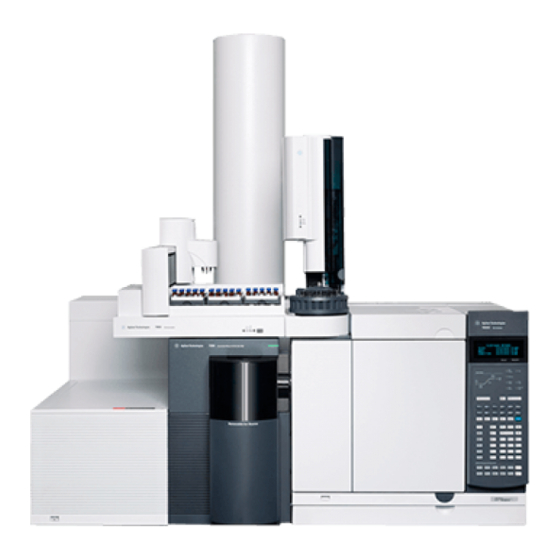
Introduction Hardware Description Figure 1 is an overview of a typical Agilent 7200 Accurate-Mass Q-TOF GC/MS system. Flight tube 7890 GC Q-TOF Lower RIS Upper RIS GC power Oven door MS power Drawer cover cover switch latch switch Figure 1... -
Page 15: Important Safety Warnings
The printed circuit boards in these instruments can be damaged by electrostatic discharge. Do not touch any of the boards unless it is absolutely necessary. If you must handle them, wear a grounded wrist strap and take other antistatic precautions. 7200 Accurate-Mass QTOF Operation Manual... - Page 16 Turn the zone off after it has reached the setpoint. If you must perform maintenance on hot parts, use a wrench and wear gloves. Whenever possible, cool the part of the instrument that you will be maintaining before you begin working on it. 7200 Accurate-Mass QTOF Operation Manual...
- Page 17 Combustible materials (or flammable/nonflammable wicking material) placed WA R N I N G under, over, or around the foreline (roughing) pump constitutes a fire hazard. Keep the pan clean, and do not leave absorbent material such as paper towels in it. 7200 Accurate-Mass QTOF Operation Manual...
-
Page 18: Safety And Regulatory Certifications
• AUS/NZ This ISM device complies with Canadian ICES-001. Cet appareil ISM est conforme a la norme NMB—001 du Canada. The 7200 Q-TOF GC/MS is designed and manufactured under a quality system registered to ISO 9001. Information The Agilent Technologies 7200 Accurate-Mass Q-TOF GC/MS meets the... - Page 19 Failure to comply with these precautions violates safety standards of design and the intended use of the instrument. Agilent Technologies assumes no liability for the customer’s failure to comply with these requirements.
- Page 20 • Ensure that all peripheral devices are also certified. • Ensure that appropriate cables are used to connect the device to peripheral equipment. • Consult your equipment dealer, Agilent Technologies, or an experienced technician for assistance. Changes or modifications not expressly approved by Agilent Technologies could void the user’s authority to operate the equipment.
-
Page 21: Intended Use
The MS should not be left vented to atmosphere for long periods. For more information, see “To Move or Store the MS” in the Agilent 7200 Q-TOF GC/MS Troubleshooting and Maintenance Manual. 7200 Accurate-Mass QTOF Operation Manual... - Page 22 Introduction 7200 Accurate-Mass QTOF Operation Manual...
- Page 23 Agilent 7200 Accurate-Mass Quadrupole Time-of-Flight GC/MS System Operation Manual Installing GC Columns Columns To Install a Capillary Column in a Split/Splitless Inlet To Condition a Capillary Column To Install a Capillary Column in the GC/MS Interface Before you can operate your GC/MS system, you must select, install, and condition a GC column.
-
Page 24: Installing Gc Columns
* Total gas flow into the MS = column flow + collision cell gas flow + reagent gas flow (if applicable) + Agilent Quick Swap flow (if applicable) † Expect degradation of spectral performance and sensitivity. 7200 Accurate-Mass QTOF Operation Manual... - Page 25 Tips and hints • The column installation procedure for the 7200 Q-TOF GC/MS is different from that for other MSs. Using the procedure from another instrument may not work and may damage the column or the MS.
-
Page 26: To Install A Capillary Column In A Split/Splitless Inlet
The GC operates at high temperatures. In order to avoid burns, do not touch any WA R N I N G parts of the GC until you are sure they are cool. Cool the oven to room temperature. 7200 Accurate-Mass QTOF Operation Manual... - Page 27 Wipe the outside of the free end of the column with a lint-free cloth moistened with methanol. Position the septum under the column nut so that the column extends 4 to 6 mm past the end of the ferrule (Figure 7200 Accurate-Mass QTOF Operation Manual...
- Page 28 Inlet column nut Septum Figure 3 Installing a capillary column for a split/splitless inlet The traditional inlet column nut is shown and the recommended self tighten- ing inlet column nut is also provided but not shown. 7200 Accurate-Mass QTOF Operation Manual...
-
Page 29: To Condition A Capillary Column
“To Install a Capillary Column in the GC/MS Interface” on page 30.) For more information about installing a capillary column, refer to Optimizing Splitless Injections on Your GC for High Performance MS Analysis, Agilent Technologies publication number 5988-9944EN. 7200 Accurate-Mass QTOF Operation Manual... -
Page 30: To Install A Capillary Column In The Gc/Ms Interface
Traditional MS interface nut materials • MS Interface column nut (05988-20066) • Ferrules, Vespel for universal column nut • 5181-3323 Ferrule, 0.4 mm VG 0.1-0.25 col 10 pk • 5062-3514 Ferrule, 0.5 mm VG 0.32 col 10 pk 7200 Accurate-Mass QTOF Operation Manual... - Page 31 While holding the column against the column cutter with your thumb, break the column against the edge of the column cutter. Inspect the end for jagged edges or burrs. If the break is not clean and even, repeat steps 5 and 6. 7200 Accurate-Mass QTOF Operation Manual...
- Page 32 14 Check the GC oven to be sure that the column does not touch the oven walls. 15 Check the nut’s tightness after one or two heat cycles; retighten as appropriate. 7200 Accurate-Mass QTOF Operation Manual...
- Page 33 To Open the Analyzer Cover for Access to the Analyzer Sideplate To Pump Down the MS To Vent the MS This chapter will explain how to perform some routine operating procedures for the 7200 Accurate-Mass Q-TOF GC/MS in EI mode. Agilent Technologies...
-
Page 34: Operating In Electron Impact (Ei) Mode
MassHunter Workstation software, refer to the manuals and online help supplied with the software for more information. Your G3851BA 7200 Q-TOF GC/MS provides the capability of operating in either EI or CI modes, using the new RIS technology. You must specify the type of ionization you are using in the Acquisition software tune file used by your method. -
Page 35: The Gc/Ms Interface
“To Install a Capillary Column in the GC/MS Interface” on page 30. The GC/MS interface operates at high temperatures. If you touch it when it is hot, it WA R N I N G will burn you. 7200 Accurate-Mass QTOF Operation Manual... - Page 36 Spring-loaded tip Column nut seal entrance to ion source GC oven IRM calibrant in Heater sensor assembly Column end protrudes 4 to 5 mm into the ionization chamber. Column not shown Figure 4 The GC/MS interface 7200 Accurate-Mass QTOF Operation Manual...
-
Page 37: Before You Turn On The Ms
Be sure to comply with local regulations. The oil mist filter supplied with the standard pump stops only pump oil. It does not trap or filter out toxic chemicals. The use of hydrogen gas is specifically prohibited with this product. WA R N I N G 7200 Accurate-Mass QTOF Operation Manual... -
Page 38: Pumping Down
Carrier gas flow is controlled by column inlet pressure in the GC. For a given inlet pressure, column flow will decrease as the GC oven temperature increases. With electronic pneumatic control (EPC) and the column mode set to Constant Flow, the same column flow is maintained regardless of temperature. 7200 Accurate-Mass QTOF Operation Manual... -
Page 39: Controlling Collision Cell Flow
Never vent the MS by allowing air in through either end of the foreline hose. Use the C A U T I O N vent valve or remove the column nut and column. Do not exceed the maximum recommended total gas flow. See Table 7200 Accurate-Mass QTOF Operation Manual... -
Page 40: Typical Vacuum Pressures In Ei Mode
7.84 * 10 2.21 * 10 If the pressure is consistently higher than those listed, refer to the online help in the MassHunter Workstation software for information on troubleshooting air leaks and other vacuum problems. 7200 Accurate-Mass QTOF Operation Manual... -
Page 41: To Set Monitors For Temperature And Vacuum Status
Procedure Select Instrument > Edit Monitors to display the Select Monitors dialog box. Figure Figure 5 Select Monitors dialog box 7200 Accurate-Mass QTOF Operation Manual... - Page 42 Select Window > Arrange Monitors, or click and drag each monitor to the desired position. See Figure 6 for one way of arranging the monitors. Figure 6 Arranging monitors To make the new settings part of the method, select Save from the Method menu. 7200 Accurate-Mass QTOF Operation Manual...
-
Page 43: To Set The Ms Analyzer Temperature
Select the Files and Reports tab then click the Save button to save the tune file with these changes. Table 4 Recommended temperature settings Zone EI operation °C MS Source °C MS Quad 7200 Accurate-Mass QTOF Operation Manual... - Page 44 The software will not allow you to exceed 200 °C for the quadrupole, or 350 °C for WA R N I N G the ion source. 7200 Accurate-Mass QTOF Operation Manual...
-
Page 45: To Set The Gc/Ms Interface Temperature From The Masshunter Workstation
Setting the interface temperature Ensure that the carrier gas is turned on and the column has been purged of air before C A U T I O N heating the GC/MS interface or the GC oven. 7200 Accurate-Mass QTOF Operation Manual... -
Page 46: To Calibrate The Column
10 Verify that the other parameters listed (temperature, inlet and outlet pressures, and gas type) are those used in the method to determine the holdup time. Change any parameters that are different than those used in your method. 7200 Accurate-Mass QTOF Operation Manual... - Page 47 Operating in Electron Impact (EI) Mode Figure 9 Calculate Column Length dialog box 11 When the new column length appears, click OK to save the changes. 12 Click OK on the Calibrate Columns screen to save the calibration. 7200 Accurate-Mass QTOF Operation Manual...
-
Page 48: To Configure The Collision Cell Gas
Click the Configuration icon and select the Modules tab to display the screen. Figure Figure 10 Configure the collision cell gas From the Collision Cell EPC drop-down menu, select N2 as the collision cell gas. Click OK to save the configuration. 7200 Accurate-Mass QTOF Operation Manual... -
Page 49: To Set The Collision Cell Gas Flow Rate
Click Apply to download the setpoints or OK to download the setpoints and close the window. To make the new settings part of the method, select Save from the Method menu. Figure 11 Setting the collision cell gas flow rate 7200 Accurate-Mass QTOF Operation Manual... -
Page 50: To Autotune The Ms For Ei Mode
Review the Tune Report. If the results are acceptable and you did not select the Save tune file when done check box, save the autotune by clicking the Files and Report tab, then click the Save button. 7200 Accurate-Mass QTOF Operation Manual... - Page 51 Operating in Electron Impact (EI) Mode See the manuals or online help provided with your MassHunter Data Acquisition Workstation software for additional information about tuning. Figure 12 EI Autotune 7200 Accurate-Mass QTOF Operation Manual...
-
Page 52: To Remove The Upper Ris Cover
Do not remove the upper RIS cover for any other reasons. Procedure 1 Grasp the cover by the outside corners. 2 Pull the cover straight up, and remove it from the instrument. Figure 13 Upper RIS cover 7200 Accurate-Mass QTOF Operation Manual... -
Page 53: To Open The Analyzer Cover For Access To The Analyzer Sideplate
“To Remove the Upper RIS Cover” on page 52. Open the latches on the analyzer cover at the front of the instrument. Swing the analyzer cover open. Analyzer cover Upper RIS cover Figure 14 Covers 7200 Accurate-Mass QTOF Operation Manual... -
Page 54: To Pump Down The Ms
EI and a CI ion source, you are prompted for the ion source type that is currently installed. Click on an EI or CI ion source type if prompted. Select the MS Tune icon from the Instrument Control panel. Select the Vacuum Control tab. 7200 Accurate-Mass QTOF Operation Manual... - Page 55 Data acquired before the MS has reached thermal equilibrium may not be reproducible. 12 Tune the MS. (See “To Autotune the MS for EI Mode” on page 50 or “To Perform a CI Autotune” on page 72.) 7200 Accurate-Mass QTOF Operation Manual...
-
Page 56: To Vent The Ms
WA R N I N G When the MS is vented, do not put the Workstation into Instrument Control view. C A U T I O N Doing so will turn on the interface heater, which can damage the column. 7200 Accurate-Mass QTOF Operation Manual... - Page 57 To Set a Reagent Gas Flow To Perform a CI Autotune This chapter provides information and instructions for operating the 7200 Q-TOF GC/MS system in Chemical Ionization (CI) mode. Most of the information in the preceding chapter is also relevant.
-
Page 58: Operating In Chemical Ionization (Ci) Mode
• Ensure the reagent gas plumbing has no air leaks. This is determined in PCI mode, checking for m/z 32 after the methane pretune. • Ensure the reagent gas inlet line is equipped with gas purifiers (not applicable for ammonia). 7200 Accurate-Mass QTOF Operation Manual... -
Page 59: The Gc/Ms Interface
GC oven temperature, but never higher than the maximum column temperature. See Also “To Install a Capillary Column in the GC/MS Interface” on page 30. 7200 Accurate-Mass QTOF Operation Manual... - Page 60 WA R N I N G will burn you. Column nut Spring-loaded tip seal entrance to ion source GC oven Reagent gas and IRM calibrant in Heater sensor assembly Column not shown Figure 16 The GC/MS interface 7200 Accurate-Mass QTOF Operation Manual...
-
Page 61: Operating The Ci Ms
Depending upon the application, use the following reagent gas flowrates during system startup: • PCI mode set reagent gas flow to 20 (1 mL/min) • NCI mode set reagent gas flow to 40 (2 mL/min) 7200 Accurate-Mass QTOF Operation Manual... -
Page 62: High Vacuum Pressure In Ci Mode
3.66e-05 3.37e-07 1.23e+01 1.62e-06 1.67e-07 1.5+02 3.71e-05 3.39e-07 1.31e+01 1.96e-06 1.67e-07 1.57+02 3.73e-05 3.41e-07 1.39e+01 2.32e-06 1.70e-07 1.63+02 3.77e-05 3.41e-07 1.46e+01 2.64e-06 1.71e-07 1.69+02 3.81e-05 3.41e-07 1.52e+01 3.00e-06 1.71e-07 1.74+02 3.83e-05 3.43e-07 1.58e+01 3.34e-06 1.72e-07 7200 Accurate-Mass QTOF Operation Manual... -
Page 63: Other Reagent Gases
The principal chemical ionization reactions encountered are described in general in the Agilent 7200 Accurate-Mass Q-TOF GC/MS Concept Guide. If you are not experienced with chemical ionization, we suggest reviewing that material before you proceed. - Page 64 Ammonia tends to break down vacuum pump fluids and seals. Ammonia CI makes more frequent vacuum system maintenance necessary. (See the Agilent 7200 Q-TOF GC/MS Troubleshooting and Maintenance Manual.) When running ammonia for 5 or more hours a day, the foreline pump must be ballasted C A U T I O N (flushed with air) for at least 1 hour a day to minimize damage to pump seals.
-
Page 65: Ci Autotune
Quad temp 150 °C 150 °C 150 °C 150 °C 150 °C 150 °C 150 °C Interface temp 280 °C 280 °C 280 °C 280 °C 280 °C 280 °C 280 °C Autotune N/A Not available 7200 Accurate-Mass QTOF Operation Manual... -
Page 66: The Flow Control Module
The instrument provides Swagelok inlet fittings for connecting the CI reagent gas. The software refers to it as CI reagent gas. Supply reagent gases at 20 to 25 psi (138 to 172 kPa) for Methane. 7200 Accurate-Mass QTOF Operation Manual... -
Page 67: To Switch From The Ei Mode To Ci Mode
Files and Report tab, then click the Save button. Table 8 Default Tune Control Limits, used by CI autotune only Reagent gas Methane Ammonia Ion polarity Positive Negative Positive Negative Abundance target 1x10 1x10 1x10 Peakwidth target Maximum repeller 7200 Accurate-Mass QTOF Operation Manual... - Page 68 • Peakwidth target Higher peakwidth values give better sensitivity, lower values give better resolution. • Maximum emission current Optimum emission current maximum for NCI is very compound-specific and must be selected empirically. Optimum emission current for pesticides, for example, may be about 200 µA. 7200 Accurate-Mass QTOF Operation Manual...
-
Page 69: To Operate The Reagent Gas Flow Control Module
In Instrument Control panel, select the MS Tune icon to display the GC/Q-TOF Tune dialog box. Select the Manual Tune tab then select the Ion Source tab to display the ion source parameters. Figure 17 CI flow control 7200 Accurate-Mass QTOF Operation Manual... - Page 70 Pumpout button - Closes the reagent gas valve for 4 minutes and evacuates the system of reagent gases. At the end of the pumpout time the selected reagent gas valve opens. 7200 Accurate-Mass QTOF Operation Manual...
-
Page 71: To Set A Reagent Gas Flow
The reagent gas is flowing into the ion source at the rate displayed next to the setpoint. Click the Files and Reports tab, then click the Save button to save your changes to the currently loaded tune file. 7200 Accurate-Mass QTOF Operation Manual... -
Page 72: To Perform A Ci Autotune
PCI source or 40% for an NCI source. Click on the Autotune tab to return to Autotune. Select the Tune from default settings check box if you are restarting the system after a system vent, major servicing, or a power outage. If you clear 7200 Accurate-Mass QTOF Operation Manual... - Page 73 12 Review the Tune Report. If the results are acceptable and you did not select the Save tune file when done check box, save the autotune by clicking the Files and Report tab, then click the Save button. 7200 Accurate-Mass QTOF Operation Manual...
- Page 74 Operating in Chemical Ionization (CI) Mode 7200 Accurate-Mass QTOF Operation Manual...
- Page 75 Agilent 7200 Accurate-Mass Quadrupole Time-of-Flight GC/MS System Operation Manual Using the Removable Ion Source The Removable Ion Source To Change the Ion Source To Install the RIS Probe Extraction Tool To Remove the Source from the Analyzer Chamber To Change the Ion Source on the RIS Probe Extraction Tool...
-
Page 76: Using The Removable Ion Source
Using the Removable Ion Source The Removable Ion Source The removable ion source (RIS) is a feature of the Agilent 7200 Q-TOF GC/MS that allows changing of the ion source without venting the instrument through the use of the RIS probe extractor tool. The source must be removed from the... - Page 77 Using the Removable Ion Source RIS handle RIS cooling chamber RIS bayonet Figure 18 RIS probe extraction tool 7200 Accurate-Mass QTOF Operation Manual...
-
Page 78: To Change The Ion Source
From MassHunter Data Acquisition software control view, click the MS Tune icon to display the GC/Q-TOF Tune dialog box. Click the Removable Ion Source tab in the GC/Q-TOF Tune screen. (Figure Figure 19 GC/Q-TOF Tune dialog box 7200 Accurate-Mass QTOF Operation Manual... - Page 79 15 Remove the RIS probe extraction tool and replace the RIS chamber cover. “To Remove the RIS Probe Extraction Tool from the Instrument” page 87. 16 Click Next to pump down the chamber behind the RIS chamber cover. 17 When prompted, click Finish. 7200 Accurate-Mass QTOF Operation Manual...
-
Page 80: To Install The Ris Probe Extraction Tool
Lower the pins into the hinge. Close the cooling chamber door, and secure the door with the latch on the right side. Return to step 5 in the “To Change the Ion Source” on page 78. 7200 Accurate-Mass QTOF Operation Manual... - Page 81 Using the Removable Ion Source Figure 20 RIS cover door Figure 21 RIS probe installed 7200 Accurate-Mass QTOF Operation Manual...
-
Page 82: To Remove The Source From The Analyzer Chamber
Do not try to guide the ion source in manually. Push the RIS handle gently and allow C A U T I O N the RIS bayonet to slide on its own. The RIS bayonet will slide in straight if it is allowed to move naturally. 7200 Accurate-Mass QTOF Operation Manual... - Page 83 Pull the RIS handle toward you, keeping the alignment guide at the 12 o’clock position, to retract the ion source into the RIS cooling chamber. Return to step 8 in the “To Change the Ion Source” on page 78. 7200 Accurate-Mass QTOF Operation Manual...
-
Page 84: To Change The Ion Source On The Ris Probe Extraction Tool
Lock the RIS cooling chamber in the open position by opening it enough to engage the locking pin on the hinge. The 7200 Q-TOF GC/MS operates at high temperatures. Ensure the source is cooled WA R N I N G to a safe temperature before attempting to remove it from the RIS cooling chamber. - Page 85 12 Raise the locking pin on the RIS cooling chamber hinge and swing it shut. 13 Secure the RIS cooling chamber to the instrument with the latch on the right side of the door. 14 Return to step 10 in the “To Change the Ion Source” on page 78. 7200 Accurate-Mass QTOF Operation Manual...
-
Page 86: To Install The Ion Source In The Analyzer Chamber
RIS bayonet. Pull the RIS handle toward you until it is fully retracted into the RIS cooling chamber. Return to step 13 in the “To Change the Ion Source” on page 78. 7200 Accurate-Mass QTOF Operation Manual... -
Page 87: To Remove The Ris Probe Extraction Tool From The Instrument
The RIS Status area on the GC/Q-TOF Tune tab must show the Gate Valve is Open and the RIS vacuum as 0.000 Torr. The 7200 Q-TOF GC/MS operates at high temperatures. Ensure the RIS cooling WA R N I N G chamber is at a safe temperature before attempting to remove it from the instrument. - Page 88 Using the Removable Ion Source 7200 Accurate-Mass QTOF Operation Manual...
-
Page 89: General Maintenance
Agilent 7200 Accurate-Mass Quadrupole Time-of-Flight GC/MS System Operation Manual General Maintenance Before Starting Maintaining the Vacuum System Maintaining the Analyzer To Disassemble the EI Ion Source To Assemble the EI Ion Source To Disassemble the CI Ion Source To Assemble the CI Ion Source... -
Page 90: Before Starting
Clean the ion source Check the carrier gas trap(s) on the GC and MS Replace the worn out parts Replace gasket on RIS probe Check the IRM vial Replace GC gas supplies * Or as needed. 7200 Accurate-Mass QTOF Operation Manual... - Page 91 Some procedures in this chapter require access to the inside of the MS while the power switch is on. Do not remove any of the electronics safety covers in any of these procedures. To reduce the risk of electric shock, follow the procedures carefully. 7200 Accurate-Mass QTOF Operation Manual...
- Page 92 Be sure to comply with your local air quality regulations. 7200 Accurate-Mass QTOF Operation Manual...
- Page 93 Always purge the MS with methane after using ammonia. Be sure to install the ammonia so the tank is in an upright position. This will help prevent liquid ammonia from getting into the flow module. 7200 Accurate-Mass QTOF Operation Manual...
-
Page 94: Maintaining The Vacuum System
Other procedures Tasks such as replacing an ion vacuum gauge should be performed only when needed by a certified Agilent service personnel. See the Agilent 7200 Accurate-Mass Q-TOF GC/MS Troubleshooting and Maintenance Manual and see the online help in the MassHunter WorkStation software for symptoms that indicate this type of maintenance is required. -
Page 95: Maintaining The Analyzer
These tasks include: • Cleaning the ion sources • Replacing filaments The Agilent 7200 Accurate-Mass Q-TOF GC/MS Troubleshooting and Maintenance Manual provides information about symptoms that indicate the need for analyzer maintenance. The troubleshooting material in the online help in the MassHunter Workstation software provides more extensive information. - Page 96 Never open the analyzer door. More information is available If you need more information about the locations or functions of analyzer components, refer to the Agilent 7200 Accurate-Mass Q-TOF GC/MS Concepts Guide. 7200 Accurate-Mass QTOF Operation Manual...
-
Page 97: To Disassemble The Ei Ion Source
Disassemble the repeller assembly by separating the repeller, the repeller cap, ring heater and sensor assembly. (See Figure 23.) Remove the clocking button from the repeller cap by removing the screw that holds it in place. (See Figure 23.) 7200 Accurate-Mass QTOF Operation Manual... - Page 98 Bayonet mount Repeller insulator Clocking button Repeller cap Repeller Ring heater assembly RIS Extraction source body Filaments Extractor lens insulator RIS Extraction lens Ion focus insulator Ion focus Screws Figure 23 Disassembling the EI ion source 7200 Accurate-Mass QTOF Operation Manual...
-
Page 99: To Assemble The Ei Ion Source
Attach the filaments with the two screws. While installing, do not overtighten the repeller nut or the ceramic repeller insulators C A U T I O N will break when the source heats up. The nut should only be finger-tight. 7200 Accurate-Mass QTOF Operation Manual... - Page 100 Bayonet mount Repeller insulator Clocking button Repeller cap Repeller Ring heater assembly RIS Extraction source body Filaments Extractor lens insulator RIS Extraction lens Ion focus insulator Ion focus Screws Figure 24 Assembling the EI source 7200 Accurate-Mass QTOF Operation Manual...
-
Page 101: To Disassemble The Ci Ion Source
Remove the two screws from the RIS bayonet mount and remove the repeller assembly. Disassemble the repeller assembly by removing the ceramic insulator and heater assembly from the repeller. (See Figure 25.) Take the repeller off the source body. 7200 Accurate-Mass QTOF Operation Manual... - Page 102 General Maintenance Bayonet mount Clocking button Ring heater / Sensor assembly Repeller RIS CI source body Filament Ion focus insulator Ion focus lens Figure 25 Disassembling the CI ion source 7200 Accurate-Mass QTOF Operation Manual...
-
Page 103: To Assemble The Ci Ion Source
Set the filament in place. Place the ion focus assembly on the source body, with the insulator against the source body. Ensure all pins are facing in the same direction. Attach with the two screws. 7200 Accurate-Mass QTOF Operation Manual... - Page 104 General Maintenance Bayonet mount Clocking button Ring heater / Sensor assembly Repeller RIS CI source body Filament Ion focus insulator Ion focus lens Figure 26 Assembling the CI ion source 7200 Accurate-Mass QTOF Operation Manual...
-
Page 105: To Clean The Ion Source
Cleaning of the source is not a scheduled maintenance procedure. The source should be cleaned whenever there are performance anomalies that are associated with a dirty ion source. See the 7200 Q-TOF GC/MS Troubleshooting and Maintenance Manual for symptoms that indicate a dirty ion source. - Page 106 • Do not use halogenated solvents. Use hexane for the final rinse. Do not use halogenated solvents to clean the CI ion source. C A U T I O N 7200 Accurate-Mass QTOF Operation Manual...
- Page 107 The filaments, source heater assembly, and insulators cannot be cleaned C A U T I O N ultrasonically. Replace these components if major contamination occurs. If the contamination is serious, such as an oil backflow into the analyzer, seriously consider replacing the contaminated parts. 7200 Accurate-Mass QTOF Operation Manual...
- Page 108 WA R N I N G precautions. Place the parts in a clean beaker. Loosely cover the beaker with clean aluminum foil (dull side down). Dry the cleaned parts in an oven at 100 °C for 5–6 minutes. 7200 Accurate-Mass QTOF Operation Manual...
-
Page 109: To Remove A Filament
29.) The analyzer, GC/MS interface, and other components in the analyzer chamber WA R N I N G operate at very high temperatures. Do not touch any part until you are sure it is cool. 7200 Accurate-Mass QTOF Operation Manual... - Page 110 General Maintenance Filaments Filament EI Source CI Source Figure 29 Changing the filament 7200 Accurate-Mass QTOF Operation Manual...
-
Page 111: To Install A Filament
78.) Autotune the MS. Do not overtighten the thumbscrew; it can cause air leaks or prevent successful C A U T I O N pumpdown. Do not use a screwdriver to tighten the thumbscrew. 7200 Accurate-Mass QTOF Operation Manual... - Page 112 General Maintenance 7200 Accurate-Mass QTOF Operation Manual...
- Page 114 Agilent Technologies © Agilent Technologies, Inc. Printed in USA, August 2014 *G3850-90008* G3850-90008...