
Related Manuals for Agilent Technologies 7200


Summary of Contents for Agilent Technologies 7200
- Page 1 Agilent 7200 Accurate-Mass/Q-TOF GC/MS System Troubleshooting and Maintenance Manual Agilent Technologies...
- Page 2 Notices Warranty Safety Notices © Agilent Technologies, Inc. 2012, 2014 No part of this manual may be reproduced in The material contained in this docu- any form or by any means (including elec- ment is provided “as is,” and is sub-...
-
Page 3: Table Of Contents
Contents Introduction Abbreviations Used The 7200 Accurate-Mass Quadrupole Time-of-Flight GC/MS System 7200 Accurate-Mass Q-TOF GC/MS Description Side Panel AC Power Connectors Back Panel Connectors Interfacing Start Events to External Devices Remote control processor Remote start signals System ready Start run input... - Page 4 Common Types of Errors Air Leaks Contamination CI Troubleshooting Common CI-Specific Problems Troubleshooting Tips and Tricks Air Leaks Pressure-Related Symptoms Signal-Related Symptoms Tuning-Related Symptoms The CI ion source is dirty Air leak General Maintenance Before Starting Scheduled maintenance Tools, spare parts, and supplies High voltage precautions Dangerous temperatures Chemical residue...
- Page 5 Materials needed Procedure To Replace the Seals in the RIS Probe Materials needed Procedure To Separate the GC from the MS Materials needed Procedure To Position the GC Next to the MS Procedure To Move or Store the MS Materials needed Procedure To Access the Left Side Lifting Handle Materials needed...
- Page 6 Vacuum System Components Common Vacuum System Problems Foreline Pump To check the oil mist filter To check the foreline pump fluid level To add foreline pump fluid To replace the foreline pump fluid Side Plate Vacuum Seals Calibration Valves EI Calibration Valve CI Calibration Valve IRM Calibration Valves Replacement Parts...
- Page 7 Important Safety Warnings Safety and Regulatory Certifications Intended Use Cleaning/Recycling the Product Moving or Storing the MS This section provides general information about the 7200 Accurate-Mass Quadrupole Time-of-Flight (Q-TOF) GC/MS System, including a hardware description and general safety warnings. Agilent Technologies...
-
Page 8: Introduction
Introduction Abbreviations Used The abbreviations in Table 1 are used in discussing this product. They are collected here for convenience. Table 1 Abbreviations Abbreviation Definition Alternating current Automatic liquid sampler Bromofluorobenzene (calibrant) Collision cell Chemical ionization Direct current DFTPP Decafluorotriphenylphosphine (calibrant) Direct insertion probe Electron impact Electronic pneumatic control... - Page 9 Introduction Table 1 Abbreviations (continued) Abbreviation Definition Positive chemical ionization PFDTD Perfluoro-5,8-dimethyl-3,6,9-trioxydodecane (calibrant) PFET 2,4,6-tris (Pentafluoroethyl)-1,3,5-triazine PFTBA Perfluorotributylamine (calibrant) Q-TOF Quadrupole time-of-flight Quad Quadrupole mass filter Radio frequency RFPA Radio frequency power amplifier Time-of-flight Torr Unit of pressure, 1 mm Hg Turbo Turbomolecular vacuum pump Troubleshooting and Maintenance Manual...
-
Page 10: The 7200 Accurate-Mass Quadrupole Time-Of-Flight Gc/Ms System
Physical description The 7200 Q-TOF GC/MS is approximately 48 cm high, 71 cm wide, and 89 cm deep. The flight tube extends 84 cm up over the top of the instrument. The RIS probe handle, when attached, extends 48 cm from the front of the instrument. - Page 11 Introduction Vacuum gauge The 7200 Q-TOF GC/MS is equipped with four ion vacuum gauges: • RIS vacuum chamber • Vacuum manifold chamber • TOF vacuum manifold chamber • Turbomolecular vacuum pumps exhaust The MassHunter Workstation can be used to read the pressure (high vacuum) in the vacuum manifold, at the turbomolecular vacuum pump discharge, and the flight tube.
-
Page 12: 7200 Accurate-Mass Q-Tof Gc/Ms Description
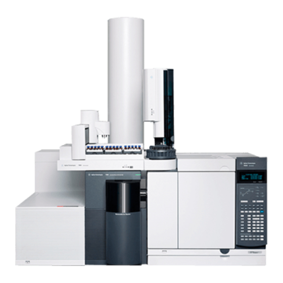
Introduction 7200 Accurate-Mass Q-TOF GC/MS Description Figure 1 is an overview of a typical 7200 Accurate-Mass Q-TOF GC/MS system. 7200 Series MS 7890 GC MS power switch GC power switch Figure 1 7200 Q-TOF GC/MS System Troubleshooting and Maintenance Manual... -
Page 13: Side Panel Ac Power Connectors
Introduction Side Panel AC Power Connectors Figure 2 Side panel power supply (left) and back panel connections (right) Foreline pump power receptacle (top) The foreline pump power cord receptacle located on the left side of the MS provides AC power for the foreline pump. If the power switch is off, no power is supplied to the foreline pump. -
Page 14: Back Panel Connectors
Introduction Back Panel Connectors Figure 3 Side panel power supply (left) and back panel connections (right) Remote start connector The remote start connector is the external connector for the remote start circuitry on the LAN/MS control card. It receives remote start signals from the LAN (I/O) connector The LAN cable from the data system is connected to the LAN communications connector. -
Page 15: Interfacing Start Events To External Devices
Introduction Interfacing Start Events to External Devices Remote control processor The remote control processor on the LAN/MS control card synchronizes start-run signals with GCs and other devices. The functions of the remote control processor are extended to the remote start (Remote) connector (Figure 4) on the back panel of the MS. -
Page 16: Start Run Input
Introduction The ready pin on the remote start connector on the GC is held low at all times except when the GC, MS, and data system are all ready. On system ready, a logic high of 5 VDC is present between that pin and any ground. This same high can be detected between the ready and ground pins on the remote start connector on the MS. -
Page 17: Important Safety Warnings
Introduction Important Safety Warnings There are several important safety notices to always keep in mind when using the MS. Many internal parts of the MS carry dangerous voltages If the MS is connected to a power source, even if the power switch is off, potentially dangerous voltages exist on: •... - Page 18 Introduction Precautions to take to prevent an explosion The use of hydrogen gas is specifically prohibited with this product. WA R N I N G You MUST make sure the top thumbscrew on the front analyzer side plate and the WA R N I N G top thumbscrew on the rear analyzer side plate are both fastened finger-tight.
- Page 19 Introduction Be careful when working behind the instrument. During cool-down cycles, the GC WA R N I N G emits hot exhaust that can cause burns. The insulation around the inlets, detectors, valve box, and the insulation cups is WA R N I N G made of refractory ceramic fibers.
-
Page 20: Safety And Regulatory Certifications
• AUS/NZ This ISM device complies with Canadian ICES-001. Cet appareil ISM est conforme a la norme NMB—001 du Canada. The 7200 Q-TOF GC/MS is designed and manufactured under a quality system registered to ISO 9001. Information The Agilent Technologies 7200 Accurate-Mass Q-TOF GC/MS meets the... - Page 21 Failure to comply with these precautions violates safety standards of design and the intended use of the instrument. Agilent Technologies assumes no liability for the customer’s failure to comply with these requirements.
- Page 22 4 Make sure that all peripheral devices are also certified. 5 Make sure that appropriate cables are used to connect the device to peripheral equipment. 6 Consult your equipment dealer, Agilent Technologies, or an experienced technician for assistance. Changes or modifications not expressly approved by Agilent Technologies could void the user’s authority to operate the equipment.
-
Page 23: Intended Use
Introduction Intended Use Agilent products must only be used in the manner described in the Agilent product user guides. Any other use may result in damage to the product or personal injury. Agilent is not responsible for any damages caused, in whole or in part, by improper use of the products, unauthorized alterations, adjustments or modifications to the products, failure to comply with procedures in Agilent product user guides, or use of the products in violation... - Page 24 Introduction Troubleshooting and Maintenance Manual...
- Page 25 See the other chapters in this manual for more information. If the material in this chapter and in the online help proves insufficient to help you diagnose a problem, contact your Agilent Technologies service representative. Agilent Technologies...
-
Page 26: General Troubleshooting
General Troubleshooting Troubleshooting Tips and Tricks Rule 1: “Look for what has been changed.” Many problems are introduced accidentally by human actions. Every time any system is disturbed, there is a chance of introducing a new problem. • If the MS was just pumped down after maintenance, suspect air leaks or incorrect assembly. -
Page 27: General Symptoms
General Troubleshooting General Symptoms This section describes symptoms you might observe when first turning on the GC/MS system. All of these symptoms would prevent operation of the system. GC does not turn on Nothing happens when the GC is switched on. The GC fans do not turn on and the keypad display does not light. - Page 28 General Troubleshooting MS turns on but then the foreline pump shuts off The MS will shut down both the foreline pump and the turbo pumps if the system fails to pump down correctly. This is usually because of a large air leak or the side plate has not sealed correctly.
-
Page 29: Chromatographic Symptoms
General Troubleshooting Chromatographic Symptoms These are symptoms you may observe in the chromatograms generated by data acquisition. In general, these symptoms do not prevent you from operating your GC/MS system. They indicate, however, that the data you are acquiring may not be the best data obtainable. These symptoms can be caused by instrument malfunctions but are more likely caused by incorrect chromatographic technique. - Page 30 General Troubleshooting • Calibration valve is not working correctly • Bad signal cable connection • Filament has failed or is not connected correctly • Bad ion source wiring connection • Bad detector wiring connection • Failed MS detector Peaks are tailing •...
- Page 31 General Troubleshooting Peaks have split tops • Bad injection technique • Injection is too large Baseline is rising • Column bleed • Other contamination Baseline is high • Column bleed • Other contamination Baseline is falling A falling baseline indicates contamination is being swept away. Wait until the baseline reaches an acceptable level.
- Page 32 General Troubleshooting Baseline wanders • Insufficient carrier gas supply pressure* • Malfunctioning flow or pressure regulator* • Intermittent leak in the GC inlet* * This could cause a fault condition in the GC that would prevent the GC from operating. Retention times for all peaks drift –...
- Page 33 General Troubleshooting • Excessive pressure in the analyzer chamber • Dirty ion source • Air leaks between chambers • Poor filament operation • Detector is not working correctly • Incorrect mass filter polarity • Collision cell voltage * This could cause a fault condition in the GC that would prevent the GC from operating.
-
Page 34: Mass Spectra General Symptoms
General Troubleshooting Mass Spectra General Symptoms This section describes symptoms you might observe in mass spectra. Some of these symptoms will appear in the mass spectra of samples. Others you will observe only in a tune report. Some of these symptoms have causes that can be corrected by the operator. - Page 35 General Troubleshooting High background • TOF vacuum or Quad vacuum • Air leak • Contamination Troubleshooting and Maintenance Manual...
-
Page 36: Pressure Symptoms
General Troubleshooting Pressure Symptoms This section describes unusual pressure readings and their possible causes. At typical column flow rates (0.5 to 2.0 mL/minute), the foreline pressure will be approximately 16 to 18 mTorr. The Quad pressure with collision cell gas on or off will be approximately 1 ×... - Page 37 General Troubleshooting Foreline pressure is too low If the pressures you observe are below 20 mTorr, check for the following: • Column (carrier gas) flow is too low • Column plugged or crushed by an overtightened nut • Collision gas flows are too low •...
-
Page 38: Temperature Symptoms
General Troubleshooting Temperature Symptoms The MS has three heated zones: • Ion source • Mass filter • GC/MS interface Each heated zone has a heater and temperature sensor. The ion source and mass filter are powered and controlled by the MS. The GC/MS interface is powered and controlled by the GC. - Page 39 General Troubleshooting • MS electronics are not working correctly * This will cause an error message. GC/MS interface will not heat up • Incorrect setpoint(s) • Setpoint entered in wrong heated zone • GC/MS interface has not had enough time to reach temperature setpoint •...
-
Page 40: Common Types Of Errors
General Troubleshooting Common Types of Errors Sometimes a problem in your MS will cause an error message to appear in the MassHunter Workstation software. Some error messages appear only during tuning. Other messages may appear during tuning or data acquisition. Some error messages are “latched.”... - Page 41 General Troubleshooting Difficulty with the high vacuum pump This indicates the pump failed to reach 50% of full speed within 10 minutes or experienced a fault. You must switch the MS off and back on to remove this error message. Be sure the turbo pump has slowed down before switching off the MS.
- Page 42 General Troubleshooting No peaks found • Emission current was set to 0 • PMT or MCP voltage is too low • Calibration vial(s) empty or almost empty • Excessive pressure in the analyzer chamber • Air leak • Signal cable is not connected •...
- Page 43 General Troubleshooting The high-vacuum pump is not ready • One of the three Turbo pumps could have failed • Turbo pump is on but has not had enough time (10 minutes) to reach 80% of its normal operating speed • Turbo pump is not working correctly •...
- Page 44 General Troubleshooting • Width gain or offset is too high • Calibration vial(s) empty or almost empty • Excessive pressure in the analyzer chamber • Air leak • MCP or PMT voltage is too low • Signal cable is not connected •...
-
Page 45: Air Leaks
General Troubleshooting Air Leaks Air leaks are a problem for any instrument that requires a vacuum to operate. Leaks are generally caused by vacuum seals that are damaged or not fastened correctly. Symptoms of leaks include: • Higher than normal analyzer chamber pressure or foreline pressure •... -
Page 46: Contamination
General Troubleshooting Contamination Contamination is usually identified by excessive background in the mass spectra. It can come from the GC or from the MS. The source of the contamination can sometimes be determined by identifying the contaminants. Some contaminants are much more likely to originate in the GC. Others are more likely to originate in the MS. - Page 47 General Troubleshooting Table 2 Common contaminants Ions (m/z) Compound Possible source 18, 28, 32, 44 or 14, 16 O, N , CO or N, O Residual air and water, air leaks, outgassing from Vespel ferrules 31, 51, 69, 100, 119, 131, PFTBA and related ions PFTBA (tuning compound) 169, 181, 214, 219, 264, 376,...
- Page 48 General Troubleshooting Troubleshooting and Maintenance Manual...
- Page 49 Pressure-Related Symptoms Signal-Related Symptoms Tuning-Related Symptoms This chapter outlines the troubleshooting of the Agilent 7200 Accurate-Mass Q-TOF GC/MS System equipped with the chemical ionization (CI) source. Most of the troubleshooting information in the previous chapter also applies to CI Q-TOFs.
-
Page 50: Ci Troubleshooting
CI Troubleshooting Common CI-Specific Problems Because of the added complexity of the parts required for CI, there are many potential problems added. By far the greatest number and most serious problems with CI are associated with leaks or contamination in the reagent gas introduction system. -
Page 51: Troubleshooting Tips And Tricks
CI Troubleshooting Troubleshooting Tips and Tricks Rule 1: “Look for what has been changed.” Many problems are introduced accidentally by human actions. Every time any system is disturbed, there is a chance of introducing a new problem. • If the MS was just pumped down after maintenance, suspect air leaks or incorrect assembly. -
Page 52: Air Leaks
CI Troubleshooting Air Leaks How do I know if I have an air leak? Large air leaks can be detected by vacuum symptoms: loud gurgling noise from the foreline pump, inability of the turbo pumps to reach 95% speed, or, in the case of smaller leaks, high pressure readings on the high vacuum gauge controller. - Page 53 CI Troubleshooting Special NCI notes Since NCI is so extremely sensitive, air leaks that are not detectable in EI or PCI can cause sensitivity problems in NCI. To check for this kind of air leak in NCI, inject OFN. The base peak should be at m/z 272. If the abundance of m/z 238 is much greater than that of m/z 272, you have an air leak.
- Page 54 CI Troubleshooting If you use argon or other introduced gas to find air leaks, this does not work well for the reagent gas flow system. It takes as long as 15 minutes for the peak to reach the ion source if the leak is at the inlet to the flow module. Flow control module Gas A select methane CI mode...
-
Page 55: Pressure-Related Symptoms
CI Troubleshooting Pressure-Related Symptoms The following symptoms are all related to high vacuum pressure. Each symptom is discussed in more detail in the following pages. The mass flow controller is calibrated for methane and the high vacuum gauge controller is calibrated for nitrogen, so these measurements are not accurate in absolute terms (Table 4). - Page 56 The foreline pump is not working properly For the standard foreline pump, replace the pump oil. If that does not help, contact your local Agilent Technologies Customer Engineer. The turbo pumps are not working properly Check the pump speed. It should be at least 95%. Contact your local Agilent Technologies service representative.
- Page 57 CI Troubleshooting Pressure does not change when reagent flow is changed The reagent gas regulator is closed Check and, if necessary, open the reagent gas regulator. The reagent gas regulator is set to the wrong pressure Set the reagent gas regulator to 10 psi (70 kPa) for methane or to 3 to 10 psi (20 to 70 kPa) for isobutane or ammonia.
-
Page 58: Signal-Related Symptoms
CI Troubleshooting Signal-Related Symptoms This section describes symptoms related to the signal. The symptom may be too much signal, too little signal, a noisy signal, or an incorrect signal. Signal-related symptoms are generally observed during tuning but may also be observed during data acquisition. - Page 59 CI Troubleshooting • Analyzer not sealed (big air leak) • Wrong tune file loaded or tune file corrupted • Ion source not assembled or connected correctly • Wrong reagent gas selected for the tune file (looking for wrong ions) No PFDTD peaks in PCI •...
- Page 60 Fix the air leak. Clean the ion source. Then bake out for two hours before tuning. See the Agilent 7200 Accurate-Mass Q-TOF GC/MS System Operation Manual. The wrong reagent gas is flowing. Turn on the correct reagent gas for your tune file.
- Page 61 CI Troubleshooting The filament or filament support is shorted to the ion source body or repeller. Inspect the filament. If necessary, realign the filament support arms. The electron inlet hole is blocked. Inspect the electron inlet hole. If necessary, clean the hole with a clean toothpick and a slurry of aluminum oxide powder and methanol.
- Page 62 CI Troubleshooting The CI ion source is dirty. Clean the ion source. See the Agilent 7200 Accurate-Mass Q-TOF GC/MS System Operation Manual. The calibration valve was not purged after the vial was refilled. Purge the calibration valve as described in “To Refill the CI Calibration Vial”...
- Page 63 New or dirty reagent gas supply tubing Purge the reagent gas supply lines and flow module for at least 60 minutes. See the Agilent 7200 Accurate-Mass Q-TOF GC/MS System Operation Manual. Air leak Check for leaks and correct any that you find. See “Air Leaks”...
-
Page 64: Tuning-Related Symptoms
CI Troubleshooting Tuning-Related Symptoms This section describes symptoms related to tuning. Most symptoms involve difficulties with tuning or with the results of tuning. The following symptoms are covered in this section: • CI ion ratio is difficult to adjust or unstable •... -
Page 65: The Ci Ion Source Is Dirty
CI Troubleshooting The CI ion source is dirty. Clean the ion source. See the Agilent 7200 Accurate-Mass Q-TOF GC/MS System Operation Manual. Cannot complete Autotune Wrong or corrupted tune file Check the tune parameters. The m/z 28/27 ion ratio (for methane) is incorrect. The correct ratio should be between 1.5 and 5.0. - Page 66 CI Troubleshooting Troubleshooting and Maintenance Manual...
-
Page 67: General Maintenance
To Separate the GC from the MS To Position the GC Next to the MS To Move or Store the MS This chapter describes maintenance procedures and requirements that are used with all Agilent 7200 Accurate Mass Q-TOF GC/MS Systems. Agilent Technologies... -
Page 68: Before Starting
General Maintenance Before Starting For your safety, read all of the information in this introduction before performing any maintenance tasks. Scheduled maintenance Common maintenance tasks are listed in Table 5. Performing these tasks when scheduled can reduce operating problems, prolong system life, and reduce overall operating costs. -
Page 69: Tools, Spare Parts, And Supplies
General Maintenance Tools, spare parts, and supplies Some of the required tools, spare parts, and supplies are included in the GC shipping kit, MS shipping kit, or MS tool kit. You must supply others yourself. Each maintenance procedure includes a required materials list. High voltage precautions When the MS is plugged in, even if the power switch is off, dangerous voltage (200/240 VAC) exists on the wiring and fuses between where the power cord... -
Page 70: Chemical Residue
General Maintenance • Vacuum pumps Never touch these parts while your MS is on. After the MS is turned off, give these WA R N I N G parts enough time to cool before handling them. The GC/MS interface heater is powered by a heated zone on the GC. The interface WA R N I N G heater can be on, and at a dangerously high temperature, even though the MS is off. -
Page 71: Electrostatic Discharge
General Maintenance The fluid in the foreline pump also collects traces of the samples being analyzed. All used pump fluid should be considered hazardous and handled accordingly. Dispose of used fluid as specified by your local regulations. When replacing pump fluid, use appropriate chemical-resistant gloves and safety WA R N I N G glasses. -
Page 72: To Refill The Ei Calibration Vial
• PFTBA (05971-60571) Refill Stop any tuning or data acquisition. Turn off the MS electronics. Remove the RIS upper cover. See the Agilent 7200 Accurate-Mass Q-TOF GC/MS System Operation Manual. Turn the calibration vial collar counterclockwise to loosen it (Figure Do not remove the collar. - Page 73 General Maintenance Turn the collar clockwise to tighten it. The collar should be snug but not overly tight. Do not use a tool to tighten the collar. It does not require that much force. 10 Reinstall the RIS upper cover. 11 In the Instrument Control panel, select the MS Tune icon to display the GC-Q-TOF Tune dialog box.
-
Page 74: To Refill The Irm Vial
General Maintenance To Refill the IRM Vial This procedure is for refilling the IRM vial without venting the MS. It includes sliding the GC away from the MS while keeping the column attached to the transfer line. Materials needed • IRM calibrant for GC/TOF 1 × 0.5 mL (5190-0531) Procedure Stop any tuning or data acquisition. - Page 75 General Maintenance Remove the metal shield covering the vial. Loosen the collar holding the vial. Remove the vial. 10 Syringe or pipette IRM into the vial. With the vial vertical, the liquid should be just below the end of the internal tube, approximately 70 µL. of sample.
-
Page 76: To Connect The Gc Nitrogen Gas Source To The Collision Cell
General Maintenance To Connect the GC Nitrogen Gas Source to the Collision Cell Materials needed • Wrench, open-end, 1/4-inch × 5/16-inch (8710-0510) • Ferrule • Swagelock nut Procedure With the MS vented, use a 5/16 in. wrench to remove the cap from the nitrogen connection located on the side of the instrument near the transfer line. -
Page 77: To Replace The Seals In The Ris Probe
General Maintenance To Replace the Seals in the RIS Probe Materials needed • Phillips screwdriver • O-ring (G7005-20030) • Seal cartridge assembly (G7005-60070) Procedure Remove the two screws on the RIS bayonet head with a Phillips screwdriver to loosen the RIS bayonet. Remove the RIS bayonet from the probe shaft. - Page 78 General Maintenance Remove the O-ring from the bushing. Wipe the probe shaft and bushing clean with a lint free cloth and alcohol. Insert a new O-ring into the bushing. Slide a new teflon seal onto the probe shaft. 10 Slide the bushing onto the probe shaft. 11 Slide the RIS cooling chamber onto to probe shaft.
-
Page 79: To Separate The Gc From The Ms
General Maintenance To Separate the GC from the MS This procedure is used for gaining access to the IRM vials and CI calibration vials or when relocating or storing the instrument. Materials needed • Ferrule, blank (5181-3308) • Interface column nut (05988-20066) •... - Page 80 General Maintenance The foreline pump may be located on the floor, on the lab bench next to or behind the MS, or under the analyzer chamber at the back of the MS. Move it as needed to provide slack in the tubing and cables. Carefully pull the GC away from the MS until you have access to the GC/MS interface cable (Figure...
- Page 81 General Maintenance GC/MS interface Interface cable Figure 11 Separating/connecting the MS and GC Troubleshooting and Maintenance Manual...
-
Page 82: To Position The Gc Next To The Ms
Push the GC towards the MS and close the gap. If needed, connect the column to the transfer line. See the Agilent 7200 Accurate-Mass Q-TOF GC/MS System Operation Manual. Wind the excess column slack in the GC oven around the column basket. -
Page 83: To Move Or Store The Ms
Do not exceed the maximum recommended total gas flow. Cool down the GC and MS. See the Agilent 7200 Accurate-Mass Q-TOF GC/MS System Operation Manual. Vent the MS. See the Agilent 7200 Accurate-Mass Q-TOF GC/MS System Operation Manual. Troubleshooting and Maintenance Manual... - Page 84 Disconnect the GC column from the transfer line and cap the end of the transfer line with a blank ferrule. See the Agilent 7200 Accurate-Mass Q-TOF GC/MS System Operation Manual. Disconnect the MS power cords on the left side of the instrument.
- Page 85 The MS must remain upright at all times. If you need to ship your MS to another C A U T I O N location, contact your Agilent Technologies service representative for advice about packing and shipping. Troubleshooting and Maintenance Manual...
-
Page 86: To Access The Left Side Lifting Handle
General Maintenance To Access the Left Side Lifting Handle RIS upper cover RIS lower Left side cover cover Front left cover Figure 14 Remove covers to access the left side lifting handles Materials needed • Screwdriver, Torx T-10 (8710-1623) or T-20 (8710-1615) The GC/MS interface, the analyzer parts, and the vacuum system operate at WA R N I N G temperatures high enough to cause serious burns. -
Page 87: Procedure
General Maintenance Before performing this procedure, move the GC away from the MS. Both the GC and MS should be shut down and disconnected from the building power supply. All gas lines must be disconnected from the MS. Procedure Pull the RIS upper cover straight up and remove it from the instrument. To remove the RIS lower cover, disengage the two captive screws on the right side edge of the lower cover. - Page 88 General Maintenance Troubleshooting and Maintenance Manual...
- Page 89 Agilent 7200 Accurate-Mass Q-TOF GC/MS System Troubleshooting and Maintenance Manual CI Maintenance To Minimize Foreline Pump Damage from Ammonia To Replace the Methane/Isobutane Gas Purifier To Clean the Reagent Gas Supply Lines To Refill the CI Calibration Vial This chapter describes maintenance procedures and requirements that are...
-
Page 90: Ci Maintenance
CI Maintenance To Minimize Foreline Pump Damage from Ammonia Air ballasting for an hour every day removes most of the ammonia from the pump oil. This will greatly increase the life of the pump. Only perform this procedure if the pump is at normal operating temperature. The water C A U T I O N vapor in air can cause condensation of the ammonia at the ballast valve if the pump is cold. -
Page 91: To Replace The Methane/Isobutane Gas Purifier
CI Maintenance To Replace the Methane/Isobutane Gas Purifier Materials needed • Methane/Isobutane gas purifier (G1999-80410) • Front ferrule for 1/8-inch tubing (5180-4110) • Rear ferrule for 1/8-inch tubing (5180-4116) • Tubing cutter (8710-1709) The methane/isobutane gas purifier needs to be replaced after four tanks of reagent gas. -
Page 92: To Clean The Reagent Gas Supply Lines
CI Maintenance To Clean the Reagent Gas Supply Lines Materials needed • Clean, dry nitrogen • Heat gun • Tubing cutter (8710-1709) Procedure If the reagent gas lines become contaminated, they can be cleaned. Disconnect the reagent gas tubing from the gas supply, the gas purifier, and the MS. -
Page 93: To Refill The Ci Calibration Vial
CI Maintenance To Refill the CI Calibration Vial Materials needed • PFDTD calibrant (8500-8510) Refill Stop any tuning or data acquisition. Set the reagent gas flow to Gas Off. Turn off the MS electronics. Cool down the GC/MS transfer line, the GC oven, and the GC inlet to ... - Page 94 CI Maintenance Do not rinse the vial with any solvents. Never expose the inside of the vial to C A U T I O N chlorinated solvents or isopropyl alcohol or water — this will result in severe loss of CI sensitivity.
- Page 95 Troubleshooting and Maintenance Manual Vacuum System Overview Maintaining the Vacuum System Vacuum System Components Common Vacuum System Problems Foreline Pump Side Plate Vacuum Seals Calibration Valves This chapter describes maintenance requirements of the Agilent 7200 Accurate Mass Q-TOF GC/MS vacuum system. Agilent Technologies...
-
Page 96: Vacuum System
Operation at high pressures also would damage analyzer components. The Agilent 7200 Accurate-Mass GC/MS System uses four vacuum pumps to obtain the vacuum levels needed. The Agilent 7200 Accurate-Mass GC/MS System uses three turbomolecular (turbo) pumps to create vacuum in the analyzer. -
Page 97: Maintaining The Vacuum System
Vacuum System Maintaining the Vacuum System Periodic maintenance As listed in Table 5 on page 68, some maintenance tasks for the vacuum system must be performed periodically. These include: • Checking the foreline pump fluid (every week) • Replacing the foreline pump oil (every 6 months) •... -
Page 98: Common Vacuum System Problems
Vacuum System Common Vacuum System Problems Air leak symptoms The most common problems associated with any vacuum system are air leaks. Symptoms of air leaks include: • Loud gurgling noise from the foreline pump (very large leak) • Inability of the turbo pumps to reach 95% speed •... -
Page 99: Foreline Pump
Vacuum System Foreline Pump This section lists procedures to maintain the foreline pump. They should be performed according to the maintenance schedule or as indicated by instrument symptoms. Figure 18 Foreline pump To check the oil mist filter Check the oil mist filter weekly for any damage and collected pump fluid. •... -
Page 100: To Check The Foreline Pump Fluid Level
Vacuum System When you close the ballast valve, you increase the efficiency of the pump. However, you N O T E lose oil to the mist filter if you don’t recycle. Check the status of your oil mist filter at least once per week to ensure that it does not fill with oil. -
Page 101: To Replace The Foreline Pump Fluid
Reinstall the fill cap. Wipe off all excess oil around and underneath of the pump. Reconnect the power cord. Start up the instrument. See the Agilent 7200 Accurate-Mass Q-TOF GC/MS System Operation Manual. To replace the foreline pump fluid Replace the pump fluid every six months or sooner if the fluid appears dark or cloudy. - Page 102 C A U T I O N substantially reduce pump life and invalidates the pump warranty. Procedure Turn off the instrument. See the Agilent 7200 Accurate-Mass Q-TOF GC/MS System Operation Manual. Unplug the power cord from the instrument. Place a container under the drain plug of the foreline pump (see Figure 63 on page 118).
- Page 103 Vacuum System The oil pan under the foreline pump can be a fire hazard Oily rags, paper towels, and similar absorbents in the oil pan could ignite and damage the pump and other parts of the MS. Combustible materials (or flammable/nonflammable wicking material) placed WA R N I N G under, over, or around the foreline (roughing) pump constitutes a fire hazard.
-
Page 104: Side Plate
Vacuum System Side Plate The side plate covers the large opening in the side of the manifold. There are no user serviceable part accessible through the hinged side plate. The analyzer assembly is attached to the side plate inside the analyzer chamber. Several electrical feedthroughs are built into the side plate. -
Page 105: Calibration Valves
Vacuum System Calibration Valves A calibration valve (Figure 19 Figure 20) is an electromechanical valve with a vial to hold the tuning compound. When a calibration valve is opened, tuning compound in the vial diffuses into the ion source. The valves are controlled by the MassHunter Workstation software. -
Page 106: Ci Calibration Valve
Vacuum System CI Calibration Valve The CI tuning compound is perfluoro-5,8-dimethyl-3,6,9-trioxidodecane (PFDTD). The CI calibration valve is part of the reagent gas flow control module. It is controlled by the MassHunter Workstation software. It opens automatically during CI autotune or manual tuning, allowing PFDTD to diffuse through the GC/MS interface and into the ion source. -
Page 107: Irm Calibration Valves
Vacuum System IRM Calibration Valves The IRM tuning compound is . There is one IRM calibration valve allowing the IRM compound held in a vial to enter the ion source. The vial contains the Internal Reference Mass Compound PFET 2,4,6-tris (Pentafluoroethyl)-1,3,5-triazine. The entry of the mass calibration compound into the ion source is controlled by the MassHunter Workstation software. - Page 108 Vacuum System Troubleshooting and Maintenance Manual...
- Page 109 Analyzer RIS Manifold Consumables and Maintenance Supplies This chapter lists parts that can be ordered for use in maintaining your 7200 Accurate-Mass Q-TOF GC/MS System. It includes most of the parts or assemblies in the MS. Most of the parts listed are not user-replaceable. They are listed here for use by Agilent Technologies service representatives.
-
Page 110: Replacement Parts
To order parts for your MS, address the order or inquiry to your local Agilent Technologies office. Supply them with the following information: • Model and serial number of your MS, located on a label on the lower left side near the front of the instrument. -
Page 111: Electronics
Replacement Parts Electronics The printed circuit boards in the MS are available only as complete assemblies. Individual electronic components are not available. This section contains the following parts: cables (Tables and 7), printed circuit boards (Table 8), and fuses and switches (Table 10). - Page 112 Replacement Parts Table 6 External cables (continued) Description Part number Power cord, Brazil C13 8121-1809 Power cord, US, 240 V 8121-0075 Table 7 Internal cables Description Part number Cable, AC inlet/outlet G3850-60844 Cable, TOF AC Power G3850-60827 Cable, SC4 Low voltage power G2571-60825 Cable, Switch board G3850-60819...
- Page 113 Replacement Parts Table 7 Internal cables (continued) Description Part number Cable, Filament lens drive G7002-60830 Cable, Gauge 3 extension G3850-60836 Cable, Turbo supply G3850-60810 Cable, Turbo controller module data G3850-60824 Cable, Turbo fan and turbo fan controller G3850-60811 Cable, Turbo pump control module, AC G3850-60825 Cable, Wire lens - 5 G3850-60833...
- Page 114 Replacement Parts Table 8 Printed circuit boards (continued) Description Part number Collision cell board G7000-65814 4.0 GHz Acquisition board G1969-61004 Motherboard, 1 GHz, 1 GB memory 0960-2490 SDRAM, 256 MB 1818-8947 PLX board G2571-61001 Main board G7005-61105 Smart card 7 G3850-67420 PCA, electrometer, tested G3850-67002...
- Page 115 Replacement Parts Fuses and power switch Table 10 Fuses and power switches Description Part number Fuse - AC Board G1960-6117 Fuse (main frame) metric 8A 250 V TD FE UL-REC CSA 2110-0969 Fuse (rough pump) metric 12.5A 250 V UL-LST CSA 2110-1398 Switch Bd PCA G1960-61000...
-
Page 116: Vacuum System
Replacement Parts Vacuum System This section lists replacement parts available for the vacuum system. It includes clamps, O-rings and seals (Table 11), foreline pump and related components (Table 12), and turbo pump vacuum system components (Table 13). O-rings and seals Table 11 O-rings and seals Description... - Page 117 Replacement Parts Table 11 O-rings and seals (continued) Description Part number Side plate O-ring 0905-1690 O-ring, pulser/detector access plate 0905-1735/ 0905-1736 Troubleshooting and Maintenance Manual...
- Page 118 Replacement Parts Foreline pump DS-202 and related parts Table 12 Foreline pump and related parts Description Part number Foreline hose assembly (hose and internal spring) 05971-60119 • Hose Clamp used with 05971-60119 1400-3241 DS 202 foreline pump, 200-240V G3850-80202 DS 202 foreline pump, 240V G3850-80240 Oil return kit 9499376...
- Page 119 Replacement Parts Turbo pump and related parts Table 13 Turbo pump MS vacuum system components Description Part number Fan (for high-vacuum pump) G1099-60564 KF25 clamp (for turbo pump outlet) 0100-0549 KF25 O-ring assembly (for turbo pump outlet) 0100-1551 Split flow turbo pump G3850-80010 Split flow turbo pump, rebuilt G3850-89010...
- Page 120 Replacement Parts Table 13 Turbo pump MS vacuum system components (continued) Description Part number Auxiliary EPC flow module with tubing (3 channel) G3850-60039 Auxiliary EPC flow module without tubing (3 channel) G7000-60506 Weldment with 1/16 in tubing end from EPC module to G3470-60550 purge ultimate union connection on GC Weldment with 1/8 in tubing end from EPC module to QTOF...
-
Page 121: Analyzer
Replacement Parts Analyzer Table 14 shows the analyzer chambers and associated parts. Table 14 Analyzer chamber and related parts Description Part number Micro Ion Gauge G1960-80303 Ion gauge baffle G7000-20049 O-ring 0905-1627 M3x12L screws 0515-0664 EI Calibration valve assembly G3850-67204 Calibration vial G3170-80002 Side plate (includes feedthrough and thumbscrews) - Page 122 Replacement Parts Table 15 Analyzer parts (continued) Description Part number RFI gasket, side G7000-80101 Mass filter ceramic support, source end G1099-20123 Mass filter heater assembly G7005-67107 Pins for source and detector end mounting G1099-20137 brackets Entrance lens G7005-67126 Quad mount grnd quad G7000-20025 Analyzer with extractor assembly, tested G7005-67201...
- Page 123 Replacement Parts Table 16 Analyzer screws (continued) Description Part number Source radiator screws 0515-1052 Screws for Quad Stop 0515-0221 EI source Table 17 Inert RIS EI Extractor Ion Source Assembly (Figure Description Part number Inert RIS ion source assembly G7005-67700 Ion focus insulator G7005-67442 Ion focus pins...
- Page 124 Replacement Parts Table 17 Inert RIS EI Extractor Ion Source Assembly (Figure 22) (continued) Description Part number Setscrew for lens stack, gold plate G1999-20021 Extractor source body G7005-67131 Troubleshooting and Maintenance Manual...
- Page 125 Replacement Parts Figure 22 Inert RIS extractor ion source Troubleshooting and Maintenance Manual...
- Page 126 Replacement Parts CI source Table 18 RIS CI ion source (Figure Description Part number RIS CI source assembly, tested G7005-67750 RIS CI bayonet catch G7005-67212 Screw, long 0515-5276 RIS CI filament G7005-80053 RIS transfer tip G7005-67542 RIS transfer tip cap G7005-67543 Ion focus lens G7005-67443...
- Page 127 Replacement Parts Figure 23 RIS CI ion source Troubleshooting and Maintenance Manual...
- Page 128 Replacement Parts RIS Probe Extraction Tool Assembly Table 19 RIS probe extraction tool assembly (Figure 24, and Figure Description Part number RIS probe extraction tool, complete cooling chamber G7005-65000 assembly RIS probe maintenance kit G7005-67170 RIS cooling chamber G7005-67156 Probe shaft G7005-67014 Bayonet tip G7005-67177...
- Page 129 Replacement Parts Figure 24 RIS probe extraction tool Figure 25 RIS probe extraction tool bayonet end Troubleshooting and Maintenance Manual...
-
Page 130: Ris Manifold
Replacement Parts RIS Manifold Table 20 RIS Manifold Description Part number RIS manifold assembly G7005-67100 Gate valve extension cable G3850-60839 Gate valve G7005-67010 Restrictor assembly G7005-67015 RIS convection vacuum gauge assembly G7005-67158 Gauge adapter G7005-20165 Frame G7005-00001 Gasket G7005-40015 Inner window G7005-20552 RIS control valve G7005-60009... - Page 131 Replacement Parts Table 20 RIS Manifold (continued) Description Part number Screw, pan with washer T20 M4x30MM-lg 0515-0669 Screw, 90 deg, T20 M4x16MM-lg 0515-1034 Fastener, strike, stainless steel 1390-1387 Fastener, catch with compression spring 1390-1386 O-ring, 2.5 inch id, 2.75 inch od, 0.125 in xsect diameter 0905-1720 Elbow, 90 deg, 1/8 inch tub od to 1/8 inch male 0100-2619...
-
Page 132: Gc/Ms Interface
Replacement Parts GC/MS Interface Table 21 lists the replacement parts related to the EI GC/MS interface. Table 21 EI GC/MS interface Description Part number GC/MS interface (complete) G7005-60400 RIS Transfer line G7005-67400 Interface Self Tightening column nut 5190-5233 Interface column nut 05980-20066 Heater clamp G7005-20410... -
Page 133: Consumables And Maintenance Supplies
Replacement Parts Consumables and Maintenance Supplies This section (Tables through 25) lists parts available for cleaning and maintaining your MS. Table 22 EI maintenance supplies Description Part number Abrasive paper, 30 µm 5061-5896 Aluminum Oxide powder, 100 g 393706201 Cloths, clean (qty 300) 05980-60051 Cloths, cleaning (qty 300) 9310-4828... - Page 134 8710-1623 Screwdrivers Torx, T-15 8710-1622 Screwdrivers Torx. T-20 8710-1615 MS shipping kit G3170-60501 RV5 pump shipping kit G7000-60500 7200 MS Shipping kits G7000-60501 7890 GC Shipping kits G3430-60581 Tweezers, non-magnetic 8710-0907 Wrenches, open-end 1/4-inch × 5/16-inch 8710-0510 Wrenches, open-end 10-mm...
- Page 135 Replacement Parts Table 24 Ferrules (continued) Description Part number For the GC inlet • 0.27-mm id, 90%/10%, for 0.10-mm id columns 5062-3518 • 0.37-mm id, 90%/10%, for 0.20-mm id columns 5062-3516 • 0.40-mm id, 90%/10%, for 0.25-mm id columns 5181-3323 •...
- Page 136 Replacement Parts Table 25 Miscellaneous parts and samples (continued) Description Part number Subpanel, rear upper G3850-67758 Panel bracket, right RIS G3850-67761 Panel, upper RIS G3850-67762 Octafluoronaphthalene, OFN, 100 fg/µL 5188-5348 PFTBA, 10 gram 8500-0656 Benzophenone, 100 pg/µL 8500-5440 PFTBA sample kit 05971-60571 Foreline pump tray G1099-00015...
- Page 138 Agilent Technologies © Agilent Technologies, Inc. Printed in USA, August 2014 *G3850-90009* G3850-90009...