Table of Contents
Advertisement
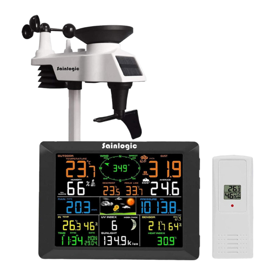
Sainlogic FT0300
Station with Wireless 8 Channel Remote
1. Introduction
Thank you for your purchase of the FT0300
Weather
station. The following user guide provides step by step
instructions for installation, operation and troubleshooting.
2. Warnings
Warning: Any metal object may attract a lightning strike, including
your weather station mounting pole. Never install the weather station
during a storm.
Warning: Installing your weather station in an elevated location
may result in injury or death. Safety goes first. Make sure your setup
and preparation is secure, and take no risks.
3. Getting Started
The FT0300 weather station consists of a display console (receiver), a
sensor array with Integrated Outdoor Transmitter and mounting
hardware.
Parts List
The FT0300 weather station consists of the following parts (as
referenced in Figure 1 ).
QTY
Display Console Frame
Dimensions (LxHxW):
215 x 22 x 158mm
1
LCD Dimensions (LxW):
170 x 125mm
Professional WIFI Weather
Monitoring User Manual
Item
Professional WIFI Wireless
1
Image
Advertisement
Table of Contents

Related Manuals for Sainlogic FT0300


Summary of Contents for Sainlogic FT0300
- Page 1 Safety goes first. Make sure your setup and preparation is secure, and take no risks. 3. Getting Started The FT0300 weather station consists of a display console (receiver), a sensor array with Integrated Outdoor Transmitter and mounting hardware.
- Page 2 Integrated Outdoor Transmitter Dimensions (LxHxW):330x150x280mm Thermo-hygrometer transmitter (FT007TH) Dimensions (LxHxW): 114.5 x 50.0 x 19mm Foot Mounting (with pole insert) Dimensions: 101x 76 x 32mm Mounting Bracket Back Plate (pole mount) Dimensions: 76 x 102 x 38mm Mounting Pole Dimensions: 300 x 300 x 20mm...
-
Page 3: Recommended Tools
Pole mounting nuts (M3) / bolts Ø3) Pole mounting nuts (M5) / bolts ( Ø5) Tapping screws Manual Power Adapter Figure 1 3.2 Recommended Tools ● Precision screwdriver (for small Phillips screws) ● Compass or GPS (for wind direction calibration) ●... - Page 4 3.3 Setup of Sensor The following illustration shows the full segment for Thermo-Hygrometer ,WIND,RAIN and UV INDEX sensor. purposes only ,as shown in Figure 2. Figure 2 3.3.1 Insert batteries into the transmitter. Locate the battery cover on the transmitter, push and open the battery compartment, as show in Figure 3.
- Page 5 Remove the battery cover on the back of the sensor by removing the set screw, as shown in Figure 4. Figure 4 Inserting 3xAA batteries in the battery compartment, as show in Figure Figure 5...
- Page 6 Close the battery cover. Make sure the gasket (around the battery compartment) is properly seated in its place prior to closing the door. Tighten the set screw. Note: Do not install the batteries backwards. You can permanently damage the sensors. The solar panel does not charge the batteries, so rechargeable batteries are not needed or recommended.
- Page 7 Figure 8 displays all four switches in the OFF position (factory default setting). Figure8 2. Channel Number: The FT0300 supports up to eight transmitters. To set each channel number (the default is Channel 1), change Dip Switches 1, 2 and 3, as referenced in Table 1.
- Page 8 DIP SWITCH FUNCTION DOWN DOWN DOWN Channel 1 DOWN DOWN Channel 2 DOWN DOWN Channel 3 DOWN Channel 4 DOWN DOWN Channel 5 DOWN Channel 6 DOWN Channel 7 Channel 8 DOWN °F °C Table 1 4. Insert two AAA batteries. 5.
- Page 9 Figure 9 (1) temperature (2) temperature units (°F vs. °C) (3) channel number (4) relative humidity 7. Close the battery cover. Make sure the gasket (around the battery compartment) is properly seated in place prior to closing the door. Tighten the set screw. 3.4 Display Console 3.4.1 Display Console Layout The display console layout is shown in Figure 10...
- Page 10 Figure 10 1. Outdoor temperature display 18. Sensor Heat index(heat index; dew 2. WIFI network point) 3. Outdoor humidity display 19. Outdoor temperature and humidity 4. Outdoor humidity HI/LO alarm display icon 20. Scroll mode indicator 5. Min/Max reset for 24h icon 21.
-
Page 11: Display Console Set Up
3.4.2 Display Console Set Up It is recommended to plug in the power supply to reduce the battery consumption and extend the service life. Note: The sensor array must be powered and updating before powering up the console, or the console will time out searching for the sensors. - Page 12 The unit will instantly display indoor temperature, humidity, pressure, tendency, moon phase, and time. The wind speed, wind gust, wind direction, rain, UV/Sunlight , thermo-hygrometer sensors, Integrated outdoor temperature and humidity will update on the display within a few minutes. Do not Press any menu buttons until the outside transmitter report in, otherwise the outdoor sensor search mode will be terminated.
-
Page 13: Sensor Operation Verification
Note: If the power adapter is plugged in, BL ON will display in the time area for three seconds when powered up. Conversely, if the power adapter is not plugged in, AC OFF will be displayed, the icon will display . 3.4.3 Sensor Operation Verification The following steps verify proper operation of the sensors prior to installing the sensor array. -
Page 14: Best Practices For Wireless Communication
2. Avoid radiant heat transfer from buildings and structures. In general, install the sensor array at least 5’ from any building, structure, ground, or roof top. 3. Avoid wind and rain obstructions. The rule of thumb is to install the sensor array at least four times the distance of the height of the tallest obstruction. - Page 15 Medium RF Signal Strength Reduction Glass (untreated) 5-15% Plastics 10-15% Wood 10-40% Brick 10-40% Concrete 40-80% Metal 90-100% 5. Final Installation of Sensors Integrated outdoor transmitter installation. Professional Wireless Weather Station can be used in both the Northern and Southern Hemispheres. Prior to installation, you will need to calibrate the wind direction.
- Page 16 Permanent wind direction error will be introduced when the wind direction sensor is not positioned correctly during installation. Northern Hemispheres Southern Hemispheres Figure 13...
- Page 17 5.2. Southern Hemispheres (SOU). For Southern Hemisphere installations, ignore these(N, S, E, W) and face the solar panel to the North (and in a sunny position) when installing the Integrated outdoor transmitter. Step 1: Install the Integrated outdoor transmitter and face the solar panel North.
- Page 18 Tighten the mounting pole to your existing mounting pole with the four¢ 5 Bolts and M5 Nuts assembly, or fix on the wall with four tapping screw, as shown in Figure15. Figure 15...
-
Page 19: Low Battery Icon
Thermo-hygrometer Transmitter installation. It is recommended you mount the Thermo-hygrometer sensor outside in a shaded area. A north facing wall is preferred because it is in the shade most of the day. Direct sunlight and radiant heat sources will result in inaccurate temperature readings. -
Page 20: Console Operation
7. Console Operation Note: The console has five keys for easy operation: MIN/MAX/-key, ALARM key, SET/MODE key, CHANNEL/+ and SNOOZE key. 7.1 Quick Display Mode Note: To exit the Quick Display Mode at any time, press the SNOOZE key of the display console. While in Normal Mode, press (do not hold) the SET/MODE key to enter the Quick Display Mode as follows: ... -
Page 21: Set (Program) Mode
7.2 Set (Program) Mode While in Normal Mode, press and hold the SET(MODE) key for at least three seconds to enter the Set Mode. The first setting will begin flashing. You can press the SET(MODE) key again to skip any step, as defined below. -
Page 22: Sensor Search Mode
11. Wind Speed Units of Measure (default: m/s). Press the SET(MODE) key again to change the wind speed units of measure . Press the [+] key or [-] key to toggle the wind speed units between m/s, km/h, mph, knots or bft. 12. -
Page 23: Reset Min/Max Record
To reacquire the lost signal, press and hold the CH/+ button for 3 seconds to enter the sensor search mode. The icon AIO will appear in the time area. You can synchronize one or all of individual sensors. press the [+] or [-] key to toggle between the following sensors: AIO. -
Page 24: Snooze Mode
Press the MIN/MAX/- key again (do not hold), the MIN icon will be displayed. Press the SET/MODE key to view min values of pressure (ABS or REL), outdoor temperature/humidity(AT or dew point),indoor temperature/humidity(temp or dew point), sensor temperature humidity, sensor dew point(dew point or heat index). Press the MIN/MAX/- key for three seconds to clear all min values.(the pressure, temperature and humidity minimum values. -
Page 25: Alarm Mode
8. Alarm Mode The FT0300 includes the following alarms: Time (There are two alarms for time. Alarm 1 and Alarm 2) ... -
Page 26: Viewing The High And Low Alarms
8.2 Viewing the High and Low Alarms To view the current alarm settings, press the ALARM key to enter the alarm mode. HI AL 1 will be displayed in the date area. At the same time Alarm 1 time and HI alarm parameters of indoor temperature/humidity, outdoor temperature/humidity, rain rate, AT, feels like, wind gust, wind average, absolute pressure, UV index, Sunlight, Sensor(CH1) temperature/humidity and dew point are displayed. - Page 27 1. Alarm hour(alarm 1) 2. Alarm minute(alarm 1) 3. Alarm hour(alarm 2) 4. Alarm minute(alarm 2) 5. Outdoor temperature high alarm 6. Outdoor temperature low alarm 7. Outdoor humidity high alarm 8. Outdoor humidity low alarm 9. Outdoor AT high alarm 10.
-
Page 28: Alarm And Command Key Beeper On/Off Mode
Note: To prevent repetitive temperature alarming, there is a 0.5 °C tolerance band. For example, if you set the high alarm to 26.7 °C and silence the alarm, the alarm icon will continue to flash until the temperature falls below 26.2°C, at which point, the alarm will reset and must increase above 26.7 °C to activate again. - Page 29 icon will appear on the LCD. The time will automatically synchronize to the internet per an hour. Note:Time synchronize method: Synchronized through internet UTC time server. WiFi Connection and Weather Servers 11. Register with WeatherCloud.net Note: This is best done on a computer desktop or laptop. Visit : https://weathercloud.net/ and enter a Username, Email and Password(It is your Login password of the websiteIt, not your email password.
- Page 30 Figure 18 3) As shown below, an email will be received in your registered mailbox . Figure 19 4) As shown below, open your mail and log in to the Web address in the mail. Figure 20...
- Page 31 5) As shown below, click “here” to enter the homepage of the weathercloud website. Figure 21 6) As shown below, enter the email address and password you just registered to enter the weathercloud website. Figure 22...
- Page 32 11.2 Add a weather station device (it may take a few minutes). Figure 23 1) After sign up you will be prompted to add a device/ Select “Create device” and enter your station’s information: Blanks with red * must be filled in.
- Page 33 Figure 25 3) As shown below, click Create. Figure 26 4) As shown below, after registering successfully, please record the Weathercloud ID and Key information for later use. (Refer to 13.6)
-
Page 34: Register At Wunderground.com (Weather Underground)
Figure 27 12. Register at Wunderground.com (Weather Underground) Note: The Weather Underground website is subject to change. Visit: https://Wunderground.com , and select the Join link in the upper right and corner and create a Free Account. 1) as shown below,Click Join Figure 28... - Page 35 2) As shown below, enter a Username, Email and Password(It is your Login password of the websiteIt, not your email password.So no privacy will be exposed). Click Sign up for free. Figure 29 3) As shown below, registration is done successfully. Figure 30 4) As shown below, click Log in and enter the email address and password you just registered.
- Page 36 Figure 31 5) As shown in the below, click My Profile. Then enter Member Settings. Figure 32 6) As shown below, click Update home location. Figure 33...
- Page 37 7) As shown below, you will then be prompted to add a device/ Select “Add New Device Figure 34 8) As shown below, click Personal Weather Station. Figure 35 9) As shown below, select Address by inputting an address or select Manual to position your address automatically.
- Page 38 Figure 36 10) As shown below, you will then be prompted to add a device/ Select “Create device” , then click I Accept and Next:Blanks with red (Required) must be filled in. Note: You can select any wifi weather station model in Device Hardware blank.
- Page 39 11) As shown below, after registering the host successfully, please record Station ID and Station Key information for later use (refer to 13.6). Figure 38 12) As shown below, registration is done successfully. Figure 39 13.WiFi Setup(Connect your Device to the Console’s WiFi) When you first power up(AC) the console, or press and hold the MIN/MAX/- button for three seconds in normal mode, the console...
- Page 40 Note: That when the console programming is complete, you will resume your default WiFi connection. Note: That you cannot connect two or more devices at the same time when WAP mode. 13.1:Example 1: Connect to the console WiFi server with a PC. Choose WiFi network settings from Windows (or search “Change Wi-Fi Settings”...
- Page 41 Figure 41 13.3: Example 3. Connect to the console WiFi server with an iPhone or iPad. Choose the Settings icon and Wi-Fi. Connect to the WeatherHomeWiFi network, as shown in Figure 42 (your WiFi network name may be slightly different, but will always begin with WeatherHome).
- Page 42 13.4: Example 4. Connect to the console WiFi server with an Android device. From the Apps icon, choose the Settings icon and Wi-Fi. Connect to the WeatherHome WiFi network, as shown in Figure 43 (your WiFi network name may be slightly different, but will always begin with WeatherHome).
- Page 43 Figure 44 Notes: Hidden SSIDs. If you have a hidden SSID, enter the SSID manually. Time Zone Settings(default: 0h). based on the number of hours from Coordinated Universal Time, or Greenwich Mean Time (GMT). The following table provides times zones throughout the world. Locations in the eastern hemisphere are positive, and locations in the western hemisphere are negative.
- Page 44 Hours from Time Zone Cities IDLW: International Date Line West NT: Nome Nome, AK AHST: Alaska-Hawaii Standard CAT: Central Alaska Honolulu, HI HST: Hawaii Standard YST: Yukon Standard Yukon Territory Los Angeles, CA, PST: Pacific Standard MST: Mountain Standard Denver, CO, USA CST: Central Standard Chicago, IL, USA EST: Eastern Standard...
- Page 45 EET: Eastern European Athens, Greece BT: Baghdad Moscow, Russia Abu Dhabi, UAE Tashkent Astana Bangkok CCT: China Coast Bejing JST: Japan Standard Tokyo GST: Guam Standard Sydney Magadan IDLE: International Date Line Wellington, New East Zealand NZST: New Zealand Standard 13.7.
-
Page 46: Viewing Your Data On Weather Underground
13.8. Once the setup is completed, disconnect your device from the console WiFi. Otherwise,the console will automatically exit WAP mode. (Figure 46) Figure 46 If the connection is successful, the Wi-Fi console’s status Wi-Fi icon will stop flashing and remain on. NOTE: When the console successfully connects to your any website of weather servers, the data signal icon will appear on the... -
Page 47: Upgrade Firmware
where STATIONID is your personal station ID (example, KCALOSAN782). Figure 47 Multiple Sensor Features Wunderground.com does not support multiple sensor channels. Note: The current temperature and humidity data is the Integrated Outdoor Transmitter. 13.10. View your data on Weathercloud. Visit the website www.weathercloud.net and sign in with your e-mail address and password. - Page 48 14.3. Once connected, enter the following IP address into the browser’s address bar: http://192.168.5.1/upgrade.html Figure 48 14.4. Once connection succeeds, it will jump to “Upload Setting” screen automatically. Figure 49 14.5. Press Select File key to select the upgraded firmware as figure...
- Page 49 Figure 50 14.6. If update successfully when press Upgrade key. Then you will see the following. Figure 51 NOTE: In this upgrade only Wifi firmware is updated. The console does not reset. 14.7. Once the upgrade is completed, the console will automatically exit WAP mode.
-
Page 50: Other Console Features
15. Other Console Features The following section describes additional features and display icons. 15.1 Weather Forecasting Note: The weather forecast or pressure tendency is based on the rate of change of barometric pressure. In general, when the pressure increases, the weather improves (sunny to partly cloudy) and when the pressure decreases, the weather degrades (cloudy to rain). -
Page 51: Moon Phase
Pressure is falling and Rainy the previous condition is cloudy. 15.3 Moon Phase The following moon phases are displayed based on the calendar date. 15.4 Feels Like Temperature and AT Feels like temperature is a combination of Heat Index and Wind Chill. At temperatures less than 4.4C(40°F), the wind chill is displayed, as shown in the National Weather Service Wind Chill Table below:... - Page 52 Figure 52 At temperatures greater than 26.7C(80°F), the heat index is displayed, as shown in the National Weather Service Heat Index Table below: Figure 53 When the temperature is between 4.4C (40°F) and 26.7C (80°F), the OUT temperature is displayed (Feels Like temperature is the same as OUT temperature).
-
Page 53: Pressure Threshold Setting
The concept of apparent temperature (AT) is a linear regression that is not restricted, and is more appropriate to outside conditions because it includes wind. and was intended as an assessment of what exposed body surfaces feel like in cold, windy conditions Regression equations of this universal scale are formulated for indoors, outdoors in shade but exposed to wind, and outdoors exposed to wind and solar radiation. - Page 54 Measurement Range Accuracy Resolution Indoor 0 to 60 °C ± 1 °C 0.1 °C Temperature Outdoor -40 to 60 °C ± 1 °C 0.1 °C Temperature Indoor ± 5% (only guaranteed 10 to 99 % Humidity between 20 to 90%) Outdoor ±...
-
Page 55: Power Consumption
16.3 Power Consumption Base station (display console) : 3 x AAA 1.5V Alkaline or Lithium batteries (not included) Adaptor: 5.9V~ 500mA (included) Thermo-hygrometer Sensor : 2 x AAA alkaline batteries or Lithium batteries (not included Integrated Outdoor Transmitter: 3xAA alkaline batteries or Lithium batteries (not included) ... -
Page 56: Troubleshooting Guide
Figure 54 2.Replace the wind, rain and thermo-hygrometer transmitter batteries once every 1-2 years 18. Troubleshooting Guide. Problem Solution Wireless remote If any of the sensor communication is lost, not reporting in dashes to console. (--.-) will be displayed on the screen. To reacquire the signal, press and hold the There are CHANNEL/+ button for 3 seconds, choose the... - Page 57 Problem Solution The maximum line of sight communication range is 100 m and 30 m under most conditions. Move the sensor assembly closer to the display console. If the sensor assembly is too close (less than 1.5m), move the sensor assembly away from the display console.
- Page 58 Problem Solution Indoor and Allow up to one hour for the sensors to stabilize Outdoor due to signal filtering. The indoor and outdoor Humidity do not humidity sensors should agree within 10 % (the agree sensor accuracy is ± 5 %). Use the calibration feature to match the indoor and outdoor humidity to a known source.
- Page 59 Problem Solution Data not reporting Confirm your password or key is correct. It is the password you www.wundergrou registered on Wunderground.com. nd.com or Your Wunderground.com password www.weatherclou cannot begin with a non-alphanumeric d.net character (a limitation of Wundeground.com, not the station). Example, $worknet is not a valid password, but worknet$ is valid.
- Page 60 ROOM 1202,GE LIN WANG YUAN, NO.96 YAN NAN ROAD. FU TIAN DISTRICT SHEN ZHEN CITY GLIANG DONG. CHINA 518001 PHONE: 8615876389177 WWW.SAINLOGIC.COM EMAIL: INFO@SAINLOGIC.COM Made in China EC | REP LOTUS GLOBAL CD., LTD. 1 FOUR SEASONS TERRACE WEST DRAYTON,...
Need help?
Do you have a question about the FT0300 and is the answer not in the manual?
Questions and answers
How do I set Time Date
To set the time and date on the Sainlogic FT0300:
1. Press the SET (MODE) key to enter time setting mode.
2. Press SET again to select the 12/24 hour format. Use [+] or [-] to switch.
3. Press SET again to set the hour. Use [+] or [-] to adjust.
4. Press SET again to set the minutes. Use [+] or [-] to adjust.
5. Press SET again to select the date format (MM-DD-YY or DD-MM-YY). Use [+] to switch.
6. Press SET again to set the month. Use [+] or [-] to adjust.
7. Press SET again to set the day. Use [+] or [-] to adjust.
8. Press SET again to set the year. Use [+] or [-] to adjust.
This answer is automatically generated