Table of Contents
Advertisement
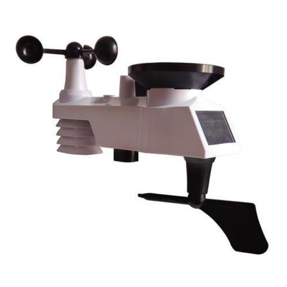
SAINLOGIC SC089
1. Introduction..........................................................................3
2. Warnings and Cautions........................................................3
3. Getting Started.....................................................................3
3.1 Parts List.........................................................................3
3.2 Recommend Tools.........................................................6
3.3 Sensor Assembly Set Up................................................6
3.3.1 Install Integrated Outdoor Sensor Battery................6
3.4 Display Console..............................................................9
3.4.1 Layout of Display Console.......................................9
3.4.2 Setup the Display Console ......................................9
3.4.3 Connect Sensors with Display Console.................11
3.5 Sensor Operation Verification.......................................11
3.6 WiFi Setup Guide.........................................................12
4. Sensors Pre-Installation.....................................................12
4.1 Test the Sensors Before Installation.............................12
4.2 Site Survey Before Installation......................................13
4.3 Best Practices for Wireless Communication.................14
5. Final Installation of Sensors...............................................15
5.1 Integrated outdoor Sensor Installation..........................15
6. Low Battery Icon................................................................20
7. Display Console Operation................................................20
7.1 Quick Display Mode......................................................20
7.2 Set (Program) Mode....................................................21
7.3 Sensor Search Mode................................................24
7.4 Max/Min Viewing and Reset Mode...............................24
7.5 Snooze Mode...............................................................26
Professional WiFi Weather
Station User Manual
- 1 -
Advertisement
Table of Contents

Related Manuals for Sainlogic SC089


Summary of Contents for Sainlogic SC089
-
Page 1: Table Of Contents
SAINLOGIC SC089 Professional WiFi Weather Station User Manual 1. Introduction................3 2. Warnings and Cautions............3 3. Getting Started..............3 3.1 Parts List.................3 3.2 Recommend Tools............6 3.3 Sensor Assembly Set Up..........6 3.3.1 Install Integrated Outdoor Sensor Battery....6 3.4 Display Console..............9 3.4.1 Layout of Display Console........9 3.4.2 Setup the Display Console ........9... - Page 2 7.6 Backlight Mode.............26 8. Alarm Mode................27 8.1 Alarm Triggered............27 8.2 View High/Low Alarm Value.........27 8.3 Setting the Alarms............28 8.4 Alarm and Key Beeper ON/OFF........30 9. Optional Calibration Mode..........30 9.1 Calibration of Temperature Mode.........31 9.2 Calibration of Humidity Mode........32 9.3 Calibration of Sensors Mode........32 10.
-
Page 3: Introduction
1.Introduction Thank you for your purchase of the SC089 Professional WIFI Wireless Weather Station. The following user guide provides step by step instructions for installation, operation and troubleshooting. 2.Warnings and Cautions Warning: Any metal object may attract a lightning strike, including your weather station mounting pole. - Page 4 Item Image Display Console Frame Dimensions : 7.56x4.76x0.79inch (192x121x20mm) LCD Dimensions: 6.7x3.1inch (171x78mm) Integrated Outdoor Transmitter Dimensions: 13x11x5.9 inch (330x280x150mm) Foot Mounting (with pole insert) Dimensions: 4x3x1.5inch (101x76x37mm) Mounting Bracket Back Plate (pole mount) Dimensions: 3x2.96x0.79inch (76x75x20mm) Mounting Pole Dimensions: 11.8x1.18x0.79inch (300x30x20mm) - 4 -...
- Page 5 Item Image Pole mounting nuts (M3) / bolts Ø3) Pole mounting nuts (M5) / bolts ( Ø5) Tapping screws Manual Power Adapter Figure 1 - 5 -...
-
Page 6: Recommend Tools
3.2 Recommend Tools Precision screwdriver (for small Phillips screws) Compass or GPS (for wind direction calibration) Adjustable Wrench. 3.3 Sensor Assembly Set Up Note: The outdoor sensor array must be powered and updating before powering up the console, or the console will stop scanning and connecting with the sensors. - Page 7 Note: Do not install the batteries backwards. You can permanently damage the outdoor sensors. The solar panel does not charge the batteries, so rechargeable batteries are not recommended. Figure 3 Remove the battery door on the back of the sensor by removing the set screw, as show in Figure 4.
- Page 8 Inserting 3 AA fresh batteries as show in Figure 5. Close the battery door. Make sure that the gasket (around the battery compartment) is properly seated in its trace prior to closing the door and Tighten the set screw. Note: We recommend installing Lithium AA batteries for outdoor sensors in cold weather environments The Integrated outdoor sensor LED indicator(White button) will light for 3 seconds, and then flash once per 16 seconds...
-
Page 9: Display Console
Figure 6 3.4 Display Console 3.4.1 Layout of Display Console The following illustration shows display console features in normal mode as below : 3.4.2 Setup the Display Console 1. Plug in the display console with power adapter. BL ON will display in the time area for three seconds when powered - 9 -... - Page 10 Note: It is recommended to plug in the power adapter to reduce the battery consumption and extend the service life 2. Display Console Batteries Installation Remove the battery door on the back of the display, as shown in Figure 7. Install three AAA (alkaline or lithium)) batteries. The display will beep once and layout of display will light up for a few seconds to verify all segments are operating properly.
-
Page 11: Connect Sensors With Display Console
3.4.3 Connect Sensors with Display Console Once the display console is powered up, it will automatically scan all the nearby Integrated Outdoor sensors. Note: Do not press any button until all the remote sensors report in the display screen, otherwise the display console will terminate to connect with remote sensors. -
Page 12: Wifi Setup Guide
rain reading on the display console is not reading 0.00. Each “ticking” represents 0.01 inch of rainfall. 2. Verify proper operating of the wind speed. Rotate the wind cups manually or with a constant speed fan. Verify the wind speed is not reading 0.0. 3. -
Page 13: Site Survey Before Installation
period, you can check out all of the functions, ensure proper operation, and familiarize with the professional weather station and calibration procedures. This will also allow you to test the wireless range of the weather station. 4.2 Site Survey Before Installation Do a site survey before installing the weather station. -
Page 14: Best Practices For Wireless Communication
4.3 Best Practices for Wireless Communication Wireless communication is susceptible to other interference, such as distance, walls and metal barriers. We recommend the following best and useful practices for trouble-free wireless communication. 1. Electro-Magnetic Interference (EMI). Keep the console several feet away from computer monitors and TVs. 2. -
Page 15: Final Installation Of Sensors
Wood 10-40% Brick 10-40% Concrete 40-80% Metal 90-100% 5. Final Installation of Sensors 5.1 Integrated Outdoor Sensor Installation This Professional Weather Station can be used in both the Northern and Southern Hemispheres. Prior to installation, you will need to calibrate the wind direction. Note: There are four alphabet letter of N, E, S and W around the wind direction.(N is North, E is East, S is South, W is West) - Page 16 5.1.1 Northern Hemispheres (NOR) References. The cardinal directions (N, S, E, W) molded on the body of the outdoor sensor are indicators for the Northern Hemisphere only. Step 1: There is a “S” indicator on the wind vane that indicates South, as shown in Figure 8.
- Page 17 North South Figure 9 Step 2: Console operation set to Southern Hemispheres( SOU in the time area) in Location division. (Check the detailed step of setting the time area in the part 17 of Chapter 7.2) Note: The location division (NOR or SOU) on the Display Console and the directions of the sensor have to be adjusted to match with your real location.
- Page 18 Figure 10 - 18 -...
- Page 19 5.1.4 Mounting & Fixing the Sensor Vertically Fasten the integrated outdoor sensor to the mounting pole brackets with two foot-mounting screws Ø3 bolts and M3 nuts. Then, tighten the mounting pole to your existing mounting pole with the four bolts ( Ø5) and nuts (M5) , or fix it on the flat surface with four tapping screws, as show in Figure 11.
-
Page 20: Low Battery Icon
6. Low Battery Icon A low battery indicator icon is shown in the display window for integrated outdoor sensor. When the low battery icon appears (The Integrated outdoor sensor battery voltage is lower than 3.6V), replace the batteries in the sensor with fresh batteries. Be sure to never mix old and new batteries, and never mix battery types such as alkaline and lithium together. -
Page 21: Set (Program) Mode
1. Time, Time/Week and Second. Press the CHANNEL/+ or MAX/MIN/- key to toggle between time, time/week and second. 2. Rainfall. Press the CHANNEL/+ or MAX/MIN/- key to toggle between 1h, 24h, week, month and total. To clear the total rain, press the CHANNEL/+ or MAX/MIN/- button until total rain is displayed. - Page 22 1. 12/24 Hour Format (default: 12h). Press the SET key again to adjust the 12/24 hour format setting (FMT). Press the CHANNEL/+ key or MAX/MIN/- key to change between 12 hour and 24 hour format. 2. Change Hour. press the SET key again to set the hour. Press the CHANNEL/+ key or MAX/MIN/- key to adjust the hour up or down.
- Page 23 9. Temperature Units of Measure (default: °F):. Press the SET key again to change the temperature units of measure. Press the CHANNEL/+ key or MAX/MIN/- key to switch between °F and °C units of measure. 10. Wind Speed Units of Measure (default: mph). Press the SET key again to change the wind speed units of measure .
-
Page 24: Sensor Search Mode
icon of Sunny, Cloudy, Partly Cloudy or Rainy. (For detailed information of this part please refer to 10.2) 16. Time SYNC(default: ON). Press the SET key again to set the network time sync. Press the CHANNEL/+ key or MAX/MIN/- key to switch between SYNC time ON/OFF of measure. - Page 25 pressure (ABS or REL), outdoor temperature and humidity (feels like or dew point) and indoor temperature and humidity Press the MAX/MIN/- key for three seconds to clear all Max values.(Rainfall, wind speed, wind gust, pressure, UV and Sunlight, temperature and humidity maximum values). Press the SNOOZE key to exit the min/max checking and reset mode, return to normal display mode.
-
Page 26: Snooze Mode
7.5 Snooze Mode If the alarm sounds, and you wish to silence the alarm, press the SNOOZE key. The alarm icon will continue to flash and the alarm will silence for five minute. Press any key (MAX/MIN/-, SET, ALARM, CHANNEL/+) to permanently exit the SNOOZE mode. -
Page 27: Alarm Mode
8. Alarm Mode The weather station includes the following alarms: Time (Alarm 1 and Alarm 2) 1h Rainfall Outdoor Temperature 24 Hour Rainfall Outdoor Humidity Absolute Pressure Outdoor Dew Point Relative Pressure ... -
Page 28: Setting The Alarms
Press ALARM key again to view the LOW alarms along with the alarm clock time in the same way as HI alarms. Press ALARM key again to return to normal mode. Note: Press the SNOOZE key at any time to return to the normal mode in HI/Low alarm mode. - Page 29 The following is a list of the individual alarm parameters that are set (in order): 1.Alarm hour(alarm 1) 15.Outdoor dew point low alarm 2.Alarm minute(alarm 1) 16.Rainfall (1h) HI alarm 3.Alarm hour(alarm 2) 17.Rainfall (24h) HI alarm 4.Alarm minute(alarm 2) 18.Absolute pressure HI alarm 5.Wind Gust HI alarm 19.Absolute pressure low alarm...
-
Page 30: Alarm And Key Beeper On/Off
8.4 Alarm and Key Beeper ON/OFF In normal mode, press and hold the ALARM key for three seconds to toggle the BZ ON (beeper on) or BZ OFF (beeper off) depending on the current setting. Display console return to normal mode without any operation in three seconds. -
Page 31: Calibration Of Temperature Mode
the internet, radio, television or newspapers. They are in a different location and typically update once per hour. The purpose of your weather station is to measure conditions of your surroundings, which vary significantly from location to location. 9.1 Calibration of Temperature Mode In normal mode, press and hold the SET and CHANNEL/+ keys at the same time for five seconds to enter the temp calibration mode. -
Page 32: Calibration Of Humidity Mode
9.2 Calibration of Humidity Mode In normal mode, press and hold the SET and MAX/MIN/- keys at the same time for five seconds to enter into the humidity calibration mode. The indoor humidity will begin flashing. Press the CHANNEL/+ key or MAX/MIN/- key to increase or decrease the humidity reading (in increments of 1%). - Page 33 Press the SET key to skip over a parameter to the next. Absolute Pressure Calibration In the calibration mode, the “ABS” symbol will display at the pressure section, the absolute pressure value will flash. (The default value is 0.00 inHg) Press the CHANNEL/+ key or MAX/MIN/- key to increase or decrease the absolute pressure value (in increments of 0.01 inHg).
- Page 34 Press the ALARM key to reset current value. Example: The calibrated pressure sources measure 25.00 inHg. The display console pressure reads 24.85 inHg. Offset = 25.00 - 24.85 = 0.15 inHg Note: The display console displays two different pressures: absolute (measured) and relative (corrected to sea-level). To compare pressure conditions from one location to another, meteorologists correct the pressure to sea-level conditions.
- Page 35 of Weather.com or Wunderground.com), and set your weather station to match the official reporting station. Wind Speed Calibration In the calibration mode, press the SET button again and the wind speed value will flash (the default is 1.00). Press the CHANNEL/+ key or MAX/MIN/- key to adjust the wind speed calibration factor from 0.75 to 1.25, where: Calibrated Wind Speed = Calibration factor x Measured Wind Speed...
- Page 36 In addition to installation challenges, wind speed bearings (any moving part) wears over time. To correct for wear, the correction value can be increased until the wind cups must be replaced. Without a calibrated source, wind speed is a difficult parameter to measure.
-
Page 37: Other Features Of Display Console
to calibration. Sunlight Calibration In the calibration mode, press the SET button again and the sunlight value will flash (the default is 1.00). Press the CHANNEL/+ key or MAX/MIN/- key to adjust the sunlight calibration factor from 0.75 to 1.25, where: Calibrated Sunlight = Calibration factor x Measured Sunlight Press and hold the CHANNEL/+ or MAX/MIN/- key for three seconds to increase or decrease rapidly. -
Page 38: Weather Icons
The weather forecast is an estimation or generalization of weather changes in the next 24 to 48 hours, and varies from location to location. The tendency is simply a tool for projecting weather changing conditions and is never to be relied upon as an accurate method to predict the weather. -
Page 39: Moon Phase
Pressure is falling Rainy and the previous condition is cloudy 10.3 Moon Phase The following moon phases are displayed based on the calendar date. 10.4 Feels Like Temperature Feels like temperature is a combination of Heat Index and Wind Chill. 1. - Page 40 2. Temperatures greater than 26.7°C(80°F), the heat index is displayed, as shown in the National Weather Service Heat Index Table below: - 40 -...
-
Page 41: Pressure Threshold Setting
10.5 Pressure Threshold Setting The pressure threshold (the negative or positive rate of change of pressure signifying a change in the weather) can be adjusted from 2 hPa to 4 hPa (default level 2 hPa). The lower the level pressure threshold setting, the higher sensitivity for weather forecast changes. - Page 42 A. Remove the rain collector funnel - 42 -...
-
Page 43: Trouble Shooting Guide
B. Install the collector funnel. Replace the Integrated outdoor sensor batteries once every 1-2 years 12. Trouble Shooting Guide Problem Solution Wireless remote not reporting If any of the sensor in to console. communication is lost, dashes (--.-) will be displayed on the There are dashes (--.-) on the screen. - Page 44 icon will be constantly displayed. Once the signal is reacquired, the remote search icon will turn off, and the current values will be displayed. The maximum line of sight communication range is 100m(330ft) and 30m(100ft) under most conditions. Move the sensor assembly closer to the display console.
- Page 45 Move the display console around electrical noise generating devices, such as computers, TVs and other wireless transmitters or receivers. Move the remote sensor to a higher location. Move the remote sensor to a closer location. Indoor and Outdoor Allow up to one hour for the Temperature do not agree sensors to stabilize due to signal filtering.
-
Page 46: Specification
sensor accuracy is ± 5 %). Use the calibration feature to match the indoor and outdoor humidity to a known source. Display console contrast is Replace console batteries weak with a fresh set of batteries. 13. Specification 13.1 Measurement Specifications The following table provides specifications for the measured parameters. - Page 47 UV Index 1 to 15+ ± 1 ± 1 Sunlight 0 to 200klux ± 15% ± 15% Rain 0 to 9999mm <15mm: <1000mm ±1 mm, (0.3mm) 15mm to >1000mm 9999mm: (1mm) ±7% Wind Direction 0 - 360º ± 10º (16 ±...
- Page 48 Adapter: 5.9V~500mA(included) Battery life: Minimum 12 months for sensors (use lithium batteries in cold weather climates less than -20°C(-4°F). Manufacturer : Sainlogic High Tech Innovation Co.,LTD F9,De Zhong Industrial Park, Li Pu Street,Shenzhen,China Post:518001 www.sainlogic.com Email: info@sainlogic.com FCC ID :2ALHJ-WS0355...
Need help?
Do you have a question about the SC089 and is the answer not in the manual?
Questions and answers
How do I reset the indoor temperature setting on my sainlogic sc089 weather station.
To reset the indoor temperature on the Sainlogic SC089 weather station, press and hold the MAX/MIN key for three seconds to clear all minimum and maximum values, including indoor temperature. After reset, the display will show the current values.
This answer is automatically generated