Table of Contents
Advertisement
SAINLOGIC WS-0835
Weather Station
1. Introduction
Thank you for your purchase of the WS-0835
Weather
station. The following user guide provides step by step
instructions for installation, operation and troubleshooting.
2. Warnings
Warning: Any metal object may attract a lightning strike, including
your weather station mounting pole. Never install the weather station in
a storm.
Warning: Installing your weather station in an elevated location
may result in injury or death. Safety goes first. Make sure your setup
and preparation is secure, and take no risks.
3. Getting Started
The WS-0835 weather station consists of a display console (receiver),
a sensor array with Integrated Outdoor Transmitter and mounting
hardware
3.1 Parts List
The WS-0835 weather station consists of the following parts (as
referenced in Figure 1 ).
QTY
Display Console
Frame Dimensions (LxHxW):
1
5.3X 1 X 3.7in
LCD Dimensions (LxW):
4.3 x 3in
Professional Wireless
Item
1
User Manual
Professional Wireless
Image
Advertisement
Table of Contents

Related Manuals for Sainlogic WS-0835


Summary of Contents for Sainlogic WS-0835
- Page 1 Safety goes first. Make sure your setup and preparation is secure, and take no risks. 3. Getting Started The WS-0835 weather station consists of a display console (receiver), a sensor array with Integrated Outdoor Transmitter and mounting hardware 3.1 Parts List...
- Page 2 Integrated Outdoor Transmitter Dimensions (LxHxW): 13 x 6 x 11in Foot Mounting (with pole insert) Dimensions: 3 x 4 x 1 ½” Mounting Bracket Back Plate (pole mount) Dimensions:3 x 3 x 1 ” Mounting Pole Dimensions: 12 x 1½ x 1” Pole mounting nuts (M3) / bolts Ø3) Pole mounting nuts (M5) /...
-
Page 3: Recommend Tools
Tapping screws Manual Power Adapter Figure 1 3.2 Recommend Tools Precision screwdriver (for small Phillips screws) Compass or GPS (for wind direction calibration) Adjustable Wrench Hammer and nail for Foot Mounting. 3.3 Sensor Assembly Set Up The following illustration shows the full segment for Thermo- Hygrometer ,WIND and RAIN transmitter .purposes only ,as shown in Figure 2. - Page 4 Figure 2 3.3.1 Insert batteries into the transmitter. Locate the battery door on the transmitter, push and open the battery compartment, as show in Figure 3. Figure 3...
- Page 5 Remove the battery door on the back of the sensor by removing the set screw, as shown in Figure 4. Figure 4 Inserting 3xAA batteries in the battery compartment, as show in Figure Figure 5...
- Page 6 Close the battery cover. Make sure the gasket (around the battery compartment) is properly seated in its place prior to closing the door. Tighten the set screw. Note: Do not install the batteries backwards. You can permanently damage the sensors. The solar panel does not charge the batteries, so rechargeable batteries are not needed or recommended.
- Page 7 Figure 7 1.Indoor humidity change 14.Time Alarm 1 indication 15.Time Alarm 2 2.Indoor humidity HI/LO alarm icon 16. DATE 3.Indoor temperature change 17. Wind direction indication 18. Wind speed units of measure 4.Temperature units (°F or °C) 19.Wind speed Gust display 5.Indoor temperature HI/LO alarm 20.Wind speed average display icon...
-
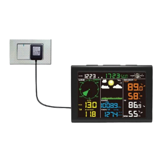
Page 8: Display Console Set Up
3.4.2 Display Console Set Up It is recommended to plug in the power supply to reduce the battery consumption and extend the service life. Note: The sensor array must be powered and updating before powering up the console, or the console will time out searching for the sensors. - Page 9 Replace the battery door, and fold out the desk stand and place the console in the upright position. The unit will instantly display indoor temperature, humidity, pressure, tendency, moon phase, and time. The wind speed, wind gust, wind direction, rain, outdoor temperature and humidity will update on the display within a few minutes.
- Page 10 Figure 10 2: Insert the DC plug correctly ; as shown in Figure 11 Figure 11 3: If you want to put it on a table or cabinet, opened the desk stand and turn the DC plug up until 90 degrees; as shown in Figure 12.
- Page 11 Figure 12 4: If you want to hang on the wall, turn the DC plug down until 0 degrees and closed the desk stand; as shown in Figure 13. Figure 13 Note: If the power adapter is plugged in, BL ON will display in the time area for three seconds when powered up.
-
Page 12: Sensor Operation Verification
3.4.2 Sensor Operation Verification The following steps verify proper operation of the sensors prior to installing the sensor array. 1. Verify proper operation of the rain gauge. Tip the sensor array back and forth several times. You should hear a “clicking”sound within the rain gauge. -
Page 13: Best Practices For Wireless Communication
56’ away. Use common sense. If the weather station is installed next to a tall building, the wind and rain will not be accurate. 4. Wireless Range. The radio communication between receiver and transmitter in an open field can reach a distance of up to 300ft, providing there are no interfering obstacles such as buildings, trees, vehicles, high voltage lines. - Page 14 5. Final Installation of Sensor Integrated outdoor transmitter installation. Professional Wireless Weather Station can be used in both the Northern and Southern Hemispheres. Prior to installation, you will need to calibrate the wind direction. 5.1. Northern Hemispheres (NOR). The cardinal directions (N, S, E, W) molded on the body of the outdoor sensor are indicators for the Northern Hemisphere only.
- Page 15 Southern Hemispheres Figure 14 5.2. Southern Hemispheres (SOU). For Southern Hemisphere installations, ignore these(N, S, E, W) and face the solar panel to the North (and in a sunny position) when installing the Integrated outdoor transmitter. Step 1: Install the Integrated outdoor transmitter and face the solar panel North.
- Page 16 Figure 15 Tighten the mounting pole to your mounting pole(purchased separately) with the four¢5 Bolts and M5 Nuts assembly, or fix on the wall with four tapping screw, as shown in Figure16.
-
Page 17: Low Battery Icon
Figure 16 6. Low Battery Icon A low battery indicator icon is shown in the display window for Integrated outdoor transmitter. When the low battery icon appears (the battery voltage is lower than 3.6V), replace the batteries in the sensor with fresh batteries. -
Page 18: Set (Program) Mode
While in Normal Mode, press (do not hold) the SET key to enter the Quick Display Mode as follows: once for time/second/date, time/week/date and time/week/year twice for rainfull. three for pressure four for outdoor dew point temperature 1. - Page 19 4. Date Format (default: MM-DD): Press the SET key again to enter the day/month format mode. Press the [+] key to switch between M- D, D-M. 5. Change Month. Press the SET key again to set the calendar month. Press the [+] key or [-] key to adjust the calendar month. 6.
-
Page 20: Sensor Search Mode
Southern Hemisphere(SOU).(refer to 5.0 Final Installation of Integrated outdoor transmitter) 7.3 Sensor Search Mode If outdoor sensor loses communication, dashes (--.-) will be displayed. To reacquire the lost signal, press and hold the CH/+ button for 3 seconds to enter the sensor search mode. 7.4 Reset Min/Max record Note: The minimum and maximum value of all channels will be cleared in the reset mode. -
Page 21: Back Light Mode
Note: If plugged into AC power, the backlight will remain on. It is not recommended leaving the backlight on for a long period of time when operating on batteries only, or the batteries will run down quickly. 8.Alarm Mode The WS-0835 includes the following alarms: Time(Alarm1 and Alarm2) ... -
Page 22: Alarm Operation
Indoor Temperature Indoor Humidity 8.1 Alarm Operation When an alarm condition is exceeded, the alarm icon will flash (visual) and the alarm beeper will sound (audible). To silence the beeper, press any key. 8.2 Viewing the High and Low Alarms To view the current alarm settings, press the ALARM key to enter the alarm mode. -
Page 23: Alarm And Command Key Beeper On/Off Mode
1. Alarm hour(alarm 1) 2. Alarm minute(alarm 1) 3. Alarm hour(alarm 2) 4. Alarm minute(alarm 2) 5. Wind Gust high alarm 6. Wind Average high alarm 7. Outdoor temperature high alarm 8. Outdoor temperature low alarm 9. Outdoor humidity high alarm 10. -
Page 24: Other Console Features
9. Other Console Features The following section describes additional features and display icons. 9.1 Weather Forecasting Note: The weather forecast or pressure tendency is based on the rate of change of barometric pressure. In general, when the pressure increases, the weather improves (sunny to partly cloudy) and when the pressure decreases, the weather degrades (cloudy to rain). -
Page 25: Moon Phase
Pressure is falling and the previous condition is partly Cloudy cloudy or Pressure is rising and the previous condition is rainy. Pressure is falling and the previous Rainy condition is cloudy. 9.3 Moon Phase The following moon phases are displayed based on the calendar date. Figure 17... -
Page 26: Pressure Threshold Setting
9.4 Pressure Threshold Setting The pressure threshold (the negative or positive rate of change of pressure signifying a change in the weather) can be adjusted from 2 mbar/hour to 4 mbar/hour (default level 2 mbar/hour). The lower the level pressure threshold setting, the higher sensitivity for weather forecast changes. -
Page 27: Measurement Specifications
Figure 19 When the temperature is between 40°F and 80°F , the OUT temperature is displayed (Feels Like temperature is the same as OUT temperature). 10. Specifications 10.1 Wireless Specifications Line of sight wireless transmission (in open air): 300ft. ... -
Page 28: Power Consumption
Measurement Range Accuracy Resolution Indoor 32 to 140 °F ± 2 °F 0.1 °F Temperature Outdoor -40 to 140 °F ± 2°F 0.1 °F Temperature ± 5% (only Indoor Humidity 10 to 99 % guaranteed between 20 to 90%) ± 5% (only Outdoor 10 to 99% guaranteed between... -
Page 29: Maintenance
11. Maintenance 1. Clean the rain gauge and wind transmitter once every 3 months. Unscrew the rain collector funnel by turning it 30°counter clockwise. Gently remove the rain collector funnel. Clean and remove any debris or insects. ... -
Page 30: Troubleshooting Guide
B: Install the collector funnel. Figure 22 2. Replace the wind, rain and thermo-hygrometer transmitter batteries once every 1-2 years 12. Troubleshooting Guide. Problem Solution Wireless remote If any of the sensor communication is lost, not reporting in to dashes (--.-) will be displayed on the screen. To console. - Page 31 Make sure the remote sensor LCD display is working and the transmitter light is flashing once per 60 seconds. Install a fresh set of batteries in the remote thermo-hygrometer. For cold weather environments, install lithium batteries. Make sure the remote sensors are not transmitting through solid metal (acts as an RF shield), or earth barrier (down a hill).
- Page 32 Manufacturer: Sainlogic High Tech Innovation Co.,LTD F9,De Zhong Industrial Park, Li Pu Street,Shenzhen,China Post:518001 Phone:+86 755 80759871 www.sainlogic.com Email:Info@sainlogic.com FCC ID :2ALHJ-WS0835...
Need help?
Do you have a question about the WS-0835 and is the answer not in the manual?
Questions and answers
I cannot get the rain collector funnel off to clean it. It turns but I don’t think it is 30 degrees and of course, I’m worried about breaking it. Any suggestions.
To safely remove the rain collector funnel from the Sainlogic WS-0835 for cleaning:
1. Unscrew the rain collector funnel by turning it 30° counterclockwise.
2. Gently remove the rain collector funnel.
After cleaning and drying, reinstall the funnel.
This answer is automatically generated
How do you get the unit to measure ambient temperature not feels like temperature
The Sainlogic WS-0835 automatically displays the outdoor (ambient) temperature as the "OUT" temperature when it is between 40°F and 80°F, and in this case, the "Feels Like" temperature is the same as the "OUT" temperature. There is no instruction in the provided context on how to manually switch between ambient and "Feels Like" temperature measurements.
This answer is automatically generated
My unit will not display outdoors Temperature's at all
The Sainlogic WS-0835 may not be displaying outdoor temperatures due to the following reasons:
1. Sensor Connection Issue – The integrated outdoor transmitter may not be properly connected to the display console. Ensure the transmitter is powered on and within range.
2. Battery Issue – The outdoor sensor may have weak or dead batteries. Replace them with a fresh set.
3. Interference – Wireless interference from other electronic devices may be disrupting the signal. Move the console and sensor away from potential sources of interference.
4. Calibration Problem – The sensor may need calibration. Use the calibration feature to match the outdoor temperature with a known source.
5. Physical Obstruction – Ensure there are no obstacles blocking the signal between the sensor and the console.
6. Defective Sensor – If none of the above solutions work, the outdoor sensor may be faulty and require replacement.
This answer is automatically generated
Only part of the display is showing
whats the benefit of pay for the app