Table of Contents
Advertisement
FT0360
1. Introduction..........................................................................1
2. Warnings and Cautions........................................................1
3. Getting Started.....................................................................1
3.1 Parts List.........................................................................1
3.2 Recommend Tools.........................................................5
3.3 Sensor Assembly Set Up................................................5
3.3.1 Wind Vane Installation..............................................6
3.3.2 Wind Cup Installation... ............................................8
3.3.3 Rain Gauge Installation............................................9
3.3.4 Battery Installation..................................................10
3.3.5 Reset Integrated Outdoor Sensor...........................11
3.4 Display Console............................................................11
3.4.1 Layout of Display Console.....................................11
3.4.2 Setup the Display Console ....................................12
3.4.3 Connect Sensors with Display Console.................13
3.5 Sensor Operation Verification.......................................14
3.6 WiFi Setup Guide.........................................................15
4. Sensors Pre-Installation.....................................................15
4.1 Test the Sensors Before Installation.............................15
4.2 Site Survey Before Installation......................................15
4.3 Best Practices for Wireless Communication.................16
5. Final Installation of Sensors...............................................18
5.1 Integrated outdoor Sensor Installation..........................18
Professional WiFi Weather Station
User Manual
Advertisement
Table of Contents

Related Manuals for Sainlogic FT0360


Summary of Contents for Sainlogic FT0360
-
Page 1: Table Of Contents
FT0360 Professional WiFi Weather Station User Manual 1. Introduction................1 2. Warnings and Cautions............1 3. Getting Started..............1 3.1 Parts List.................1 3.2 Recommend Tools............5 3.3 Sensor Assembly Set Up..........5 3.3.1 Wind Vane Installation..........6 3.3.2 Wind Cup Installation..........8 3.3.3 Rain Gauge Installation..........9 3.3.4 Battery Installation..........10... - Page 2 6. Low Battery Icon..............23 7. Display Console Operation..........23 7.1 Quick Display Mode............23 7.2 Set (Program) Mode............24 7.3 Sensors Search Mode..........27 7.4 Max/Min Viewing and Reset Mode.......27 7.5 Snooze Mode...............28 7.6 Backlight Mode.............29 8. Alarm Mode................30 8.1 Alarm Triggered............30 8.2 View High/Low Alarm Value.........30 8.3 Setting the Alarms............31 8.4 Alarm and Key Beeper ON/OFF........33 9.
-
Page 3: Introduction
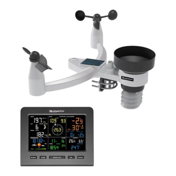
1.Introduction Thank you for your purchase of the Professional WIFI Wireless Weather Station. The following user guide provides step by step instructions for installation, operation and troubleshooting. 2.Warnings and Cautions Warning: Any metal object may attract a lightning strike, including your weather station mounting pole. Never install the weather station in a storm. - Page 4 Item Image Display Console: Frame Dimensions : 6.5X5.32X0.71inch (165×135×18mm) LCD Dimensions: 5.12 x 3.16inch(130×80mm) Integrated Outdoor Transmitter Dimensions: 15x7.1x11inch (380x180x280mm) Wind Vane Dimensions:6.7x1.6x2inch (170x40 x 50mm) Wind speed Dimensions: 5.1x 5.1x1.6inch (130x130x40mm) Rain Funnel Dimensions:4.7x2.8inch (Φ120x70mm) - 2 -...
- Page 5 Item Image Washer(Metal gasket) Pole Mounting U-bolt Nuts (M5) U-Bolt (M5) Dimensions: 2.4x2.4x0.2inch (60x60x5mm) L-shaped Stainless Steel base Dimensions: 3x1.6x0.6inch (75x40x15mm) Wrench (M5) Dimensions: 2.6x0.8x0.08inch (65x20x2mm) - 3 -...
- Page 6 Item Image Screwdriver (M3) Dimensions: 0.4x3.5inch (Φ10x90mm) Wind Vane and wind Cup mounting screws (Ø3) Dimensions: M2*6mm(0.23inch) Wind Vane and wind Cup Waterproof rubber plug Dimensions: 0.16x0.12inch (Φ4 x 3mm) Manual Power Adapter Figure 1 - 4 -...
-
Page 7: Recommend Tools
3.2 Recommend Tools Precision screwdriver (for small Phillips screws) Compass or GPS (for wind direction calibration) Adjustable Wrench. 3.3 Sensor Assembly Set Up Note: The outdoor sensor array must be powered and updating before powering up the console, or the console will stop scanning and connecting with the sensors. -
Page 8: Wind Vane Installation
3.3.1 Wind Vane Installation 1) Find the “ S ” Letters on the wind vane shaft. 2) Align the wind vane with the shaft axie and push into the top of the wind vane sensor. - 6 -... - Page 9 3) Tighten the set screw with screwdriver, until the wind van cannot be removed from the axle. 4) Insert the waterproof rubber plug into the wind vane hole and rotate to make sure it spin freely. - 7 -...
-
Page 10: Wind Cup Installation
3.3.2 Wind Cup Installation 1) Align the wind cup with the shaft axle and push into the top of the wind speed sensor. 2) Tighten the set screw with screwdriver, until the wind van cannot be removed from the axle. - 8 -... -
Page 11: Rain Gauge Installation
3) Insert the waterproof rubber plug into the wind vane hole and rotate to make sure it spin freely. ③Insert Black Waterproof rubber 3.3.3 Rain Gauge Installation 1) Align the rain collector with the bucket notch and push into the top of the bucket. - 9 -... -
Page 12: Battery Installation
2) Rotate the rain collector clockwise and make sure it installed tightly. 3.3.4 Battery Installation 1) Locate the battery door on the back, push outwards firstly and push upwards to open the battery door. Push battery box Push upwards ② outwards along the to open battery arrow. -
Page 13: Reset Integrated Outdoor Sensor
3.3.5 Reset Integrated Outdoor Sensor Note: If the sensor does not power up after inserting the batteries, press the reset button as shown in Figure 3. Figure 3 3.4 Display Console 3.4.1 Layout of Display Console The full segment LCD display for feature description purposes when powered on and will appear like below during normal operation. -
Page 14: Setup The Display Console
3.4.2 Setup the Display Console 1. Plug in the display console with power adapter. BL ON will display in the time area for three seconds when powered up. Conversely, The AC OFF icon will display . Note: It is recommended to plug in the power adapter to reduce the battery consumption and extend the service life - 12 -... -
Page 15: Connect Sensors With Display Console
2. Display Console Batteries Installation Remove the battery door on the back of the display, as shown in Figure 4. Install three AAA (alkaline or lithium)) batteries. The display will beep once and layout of display will light up for a few seconds to verify all segments are operating properly. -
Page 16: Sensor Operation Verification
Note: While in the search mode, the remote search icon will be constantly displayed until all the measured values received. The console will automatically switch to the normal mode from which all further settings can be performed. When connected with the Integrated Outdoor Sensor, the measured value (Outdoor temperature, humidity, wind speed, wind direction, wind gust and average, rainfall, UV and Sunlight index, Dew point and feels like) will show up on the... -
Page 17: Wifi Setup Guide
the console and sensor array in the same location (about 5 to 10’ (1.5 to 3 meters) apart). The sensors should be within 4°F /2°C (the accuracy is ± 2°F/1°C). Allow about 30 minutes for both sensors to stabilize. 4. Verify proper operation of in/outdoor humidity. Verify the indoor and outdoor humidity. -
Page 18: Best Practices For Wireless Communication
Do a site survey before installing the weather station. Take the following points into Consider: 1. You must clean the rain gauge once per year and change the batteries every two years. Provide as easy access to the weather station. 2. - Page 19 1. Electro-Magnetic Interference (EMI). Keep the console several feet away from computer monitors and TVs. 2. Radio Frequency Interference (RFI). If you have other 433 MHz devices and communication is intermittent, try turning off these other devices for troubleshooting purposes. You may need to relocate the wireless transmitters or receivers to avoid intermittent communication.
-
Page 20: Final Installation Of Sensors
Metal 90-100% 5. Final Installation of Sensors 5.1 Integrated Outdoor Sensor Installation This Professional Weather Station can be used in both the Northern and Southern Hemispheres. Prior to installation, you will need to calibrate the wind direction. Note: There are four alphabet letter of N, E, S and W around the wind direction.(N is North, E is East, S is South, W is West) Northern Hemispheres... - Page 21 Step 1: There is a “S” indicator on the wind vane that indicates South, as shown in Figure 5. Check the wind directions with compass and Align this “S” marker in the direction of South. Figure 5 Step 2: Console operation set to Northern Hemispheres( NOR in the time area) in Location division.
- Page 22 Step 1: Install the Integrated outdoor transmitter and face the solar panel to the North. South North Figure 6 Step 2: Console operation set to Southern Hemispheres( SOU in the time area) in Location division. (Check the detailed step of setting the time area in the part 17 of Chapter 7.2) Note: The location division (NOR or SOU) on the Display Console and the directions of the sensor have to be adjusted to match with your real location.
- Page 23 5.1.3 Mounting & Fixing the Sensor Fasten the integrated outdoor sensor to the mounting pole. U-Bolts accept a mounting pole (not included) diameter of 30-45mm. 1) Insert the iron pipe(Mounting pole) into the U-bolt. 2) Place the washer and the nuts on the U-bolts, and use the wrench to rotate clockwise and tightly.
- Page 24 - 22 -...
-
Page 25: Low Battery Icon
6. Low Battery Icon A low battery indicator icon is shown in the display window for integrated outdoor sensor. When the low battery icon appears (The Integrated outdoor sensor battery voltage is lower than 3.6V), replace the batteries in the sensor with fresh batteries. Be sure to never mix old and new batteries, and never mix battery types such as alkaline and lithium together. -
Page 26: Set (Program) Mode
1. Time, Time/Week and Second. Press the CHANNEL/+ or MAX/MIN/- key to toggle between time, time/week and second. 2. Rainfall. Press the CHANNEL/+ or MAX/MIN/- key to toggle between rate, 24h, week, month and total. To clear the total rain, press the CHANNEL/+ or MAX/MIN/- button until total rain is displayed. - Page 27 1. Time SYNC(default: ON). Press the SET key again to set the network time sync. Press the CHANNEL/+ key or MAX/MIN/- key to switch between SYNC time ON/OFF of measure. Synchronize the time of the device with WiFi. 2. 12/24 Hour Format (default: 24h). Press the SET key again to adjust the 12/24 hour format setting (FMT).
- Page 28 be programmed to clear daily (at midnight) or manually. Press the CHANNEL/+ key or MAX/MIN/- key to switch between ON (Clears 24h) and OFF (Manually). 10. Temperature Units of Measure (default: °C):. Press the SET key again to change the temperature units of measure. Press the CHANNEL/+ key or MAX/MIN/- key to switch between °F and °C units of measure.
-
Page 29: Sensors Search Mode
16. Sunlight Display Units (default: W/ ㎡ ). Press the SET key again to change the sunlight units of measure. Press the CHANNEL/+ key or MAX/MIN/- key to toggle the sunlight units between , W/㎡, fc or lux. 17. Location Division. (default: Northern Hemisphere). Press the SET key again to change the location division. -
Page 30: Snooze Mode
Press the MAX/MIN/- key for three seconds to clear all Max values.(Rainfall, wind speed, wind gust, pressure, UV and Sunlight, temperature and humidity maximum values). Press the SNOOZE key to exit the min/max checking and reset mode, return to normal display mode. Note: The Maximum values will display the current values after reset. -
Page 31: Backlight Mode
Press any key (MAX/MIN/-, SET, ALARM, CHANNEL/+) to permanently exit the SNOOZE mode. 7.6 Backlight Mode 7.6.1 Adjustable Brightness of Backlight There are 3 levels of brightness of display backlight. When the backlight is on, press SNOOZE key to switch between the 3 levels. -
Page 32: Alarm Mode
for five seconds, and if no operation is performed for three seconds, the backlight will turn off. 8. Alarm Mode The weather station includes the following alarms: Time (Alarm 1 and Alarm 2) Rate Rainfall Outdoor Temperature ... -
Page 33: Setting The Alarms
humidity, rain rate, AT, feels like, wind gust, wind average, absolute pressure, UV index, Sunlight are displayed. Press SET/MODE key to view Alarm 2 time and HI alarm parameters of indoor dew point, 24h rainfall, outdoor dew point,and relative pressure. Press ALARM key again to view the LOW alarms along with the alarm clock time in the same way as HI alarms. - Page 34 Press the ALARM key to turn on (the alarm icon will appear ) and off the alarm. Press the SNOOZE key twice at any time to return to the normal mode. After 30 seconds of inactivity, the alarm mode will time out and return to normal mode. The following is a list of the individual alarm parameters that are set (in order): 1.Alarm hour(alarm 1)
-
Page 35: Alarm And Key Beeper On/Off
Note: To prevent repetitive alarming of humidity, there is a 4% tolerance band in humidity alarm. For example, if you set the high alarm to 60% and silence the alarm, the alarm icon will continue to flash until the humidity falls below 56%, at which point, the alarm will reset and must increase above 60% to activate again. -
Page 36: Calibration Of Temperature Mode
The purpose of calibration is to fine tune or correct for any sensor error associated with the devices margin of error. The measurement can be adjusted from the console to calibrate to a known source. Calibration is only useful if you have a known calibrated source you can compare it against, and is optional. -
Page 37: Calibration Of Humidity Mode
To exit the temperature calibration mode at any time, press the SNOOZE/LIGHT button on the top of the display console. If no operation is performed, the calibration mode will timeout in 30 seconds. 9.2 Calibration of Humidity Mode In normal mode, press and hold the SET and MAX/MIN/- keys at the same time for five seconds to enter into the humidity calibration mode. -
Page 38: Calibration Of Sensors Mode
an accurate source, such as a sling psychrometer or Humidipaks One Step Calibration kit. 9.3 Calibration of Sensors Mode In normal mode, press and hold the SET and ALARM keys at the same time for five seconds to enter the pressure, wind gust, rainfall and sunlight calibration mode. - Page 39 Relative Pressure Calibration In the calibration mode, press the SET key again, the “REL” symbol will display at the pressure section, the relative pressure value will flash. (The default value is 0.00 inHg) Press the CHANNEL/+ key or MAX/MIN/- key to increase or decrease the relative pressure value (in increments of 0.01 inHg).
- Page 40 The standard sea-level pressure is 29.92 in Hg (1013.2hpa). This is the average sea-level pressure around the world. Relative pressure measurements greater than 29.92 inHg (1013.2hpa) are considered high pressure and relative pressure measurements less than 29.92 inHg are considered low pressure.
- Page 41 Discussion: Wind speed and wind gust are adversely affected by installation constraints. The rule of thumb is to install the weather station four times the distance of the height of the tallest obstruction (for example, a 6 m house would require an installation 24 m away).
- Page 42 Press the ALARM key to reset current value. Discussion: The rain collector is calibrated at the factory based on the funnel diameter. The bucket tips every 0.01” of rain (referred to as resolution). The accumulated rainfall can be compared to a sight glass rain gauge with an aperture of at least 4”.
-
Page 43: Other Features Of Display Console
10. Other Features of Display Console 10.1 Weather Forecasting Note: The weather forecast or pressure tendency is based on the rate of change of barometric pressure. In general, when the pressure increases, the weather improves (sunny to partly cloudy) and when the pressure decreases, the weather degrades (cloudy to rain). -
Page 44: Moon Phase
Pressure is falling and the previous condition is sunny Partly or Pressure is Cloudy rising and the previous condition is cloudy Pressure is falling and the previous condition is partly Cloudy cloudy or Pressure is rising and the previous condition is rainy. -
Page 45: Feels Like And At Temperature
10.4 Feels Like and AT Temperature 10.4.1 Feels Like Temperature Feels like temperature is a combination of Heat Index and Wind Chill. 1. Temperatures less than 4.4°C(40°F), the wind chill is displayed, as shown in the National Weather Service Wind Chill Table below: - 43 -... - Page 46 2. Temperatures greater than 26.7°C(80°F), the heat index is displayed, as shown in the National Weather Service Heat Index Table below: 10.4.2 Apparent Temperature (AT) AT is a linear regression that is not restricted, and is more appropriate to outside conditions because it includes wind, and was intended as an assessment of what exposed body surfaces feel like in cold, windy conditions Regression equations of this universal scale are formulated for...
-
Page 47: Pressure Threshold Setting
10.5 Pressure Threshold Setting The pressure threshold (the negative or positive rate of change of pressure signifying a change in the weather) can be adjusted from 2 hPa to 4 hPa (default level 2 hPa). The lower the level pressure threshold setting, the higher sensitivity for weather forecast changes. - Page 48 The maximum line of sight communication range is 100m(330ft) and 30m(100ft) under most conditions. Move the sensor assembly closer to the display console. If the sensor assembly is too close (less than 1.5m/5ft), move the sensor assembly away from the display console.
-
Page 49: Specification
Temperature do stabilize due to signal filtering. The not agree indoor and outdoor temperature sensors should agree within 2°C/4°F) (the sensor accuracy is ± 1°C/2°F)). Use the calibration feature to match the indoor and outdoor temperature to a known source. Indoor and Outdoor Allow up to one hour for the sensors to Humidity do not... - Page 50 Outdoor -40 to 60 °C ± 1 °C 0.1 °C(°F) Temperature (-40 to 140°F) (± 2°F)) Indoor Humidity 10 to 99 % ± 5% (only guaranteed between 20 to 90%) Outdoor 10 to 99% ± 5% (only Humidity guaranteed between 20 to 90%) UV Index 1 to 15+...
- Page 51 Barometric 300 to 1100 ± 3 hpa 0.1 hpa Pressure: 12.2 Wireless Specifications Wireless Transmit Range (in open air): 330ft (100m) Frequency: 433MHz Integrated Outdoor Sensor Data Update Period: 12.3 Power Consumption Display Console 3 x AAA 1.5V Alkaline or Lithium batteries (not included) Integrated Outdoor 3xAA alkaline batteries or Lithium...
- Page 52 - 50 -...
Need help?
Do you have a question about the FT0360 and is the answer not in the manual?
Questions and answers