Table of Contents
Advertisement
SAINLOGIC WS-0835 Plus
1.Introduction
Thank you for your purchase of the WS-0835 Plus
station. The following user guide provides step by step instructions for installation,
operation and troubleshooting.
2.Warnings
Warning: Any metal object may attract a lightning strike, including your weather
station mounting pole. Never install the weather station in a storm.
Warning: Installing your weather station in an elevated location may result in injury or
death. Safety goes first. Make sure your setup and preparation is secure, and take no risks.
3.Getting Started
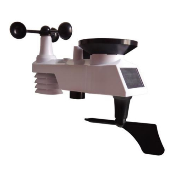
The WS-0835 Plus weather station consists of a display console (receiver), a sensor array
with Integrated Outdoor Transmitter and mounting hardware
Parts List
The weather station consists of the following parts (as referenced in Figure 1 ).
QTY
Display Console
Frame Dimensions (LxHxW):
1
5.3X 1 X 3.7in
LCD Dimensions (LxW):
4.3 x 3in
Integrated Outdoor
Transmitter
1
Dimensions (LxHxW):
13 x 6 x 11in
Weather Station
Item
1
Professional WIFI Wireless
User Manual
Professional WIFI Wireless Weather
Image
Advertisement
Table of Contents

Subscribe to Our Youtube Channel
Related Manuals for Sainlogic WS-0835 Plus Professional


Summary of Contents for Sainlogic WS-0835 Plus Professional
- Page 1 SAINLOGIC WS-0835 Plus Professional WIFI Wireless Weather Station User Manual 1.Introduction Thank you for your purchase of the WS-0835 Plus Professional WIFI Wireless Weather station. The following user guide provides step by step instructions for installation, operation and troubleshooting. 2.Warnings Warning: Any metal object may attract a lightning strike, including your weather station mounting pole.
- Page 2 Item Image Foot Mounting (with pole insert) Dimensions: 3 x 4 x 1 ½” Mounting Bracket Back Plate (pole mount) Dimensions:3 x 3 x 1 ” Mounting Pole Dimensions: 12 x 1½ x 1” Pole mounting nuts (M3) / bolts Ø3) Pole mounting nuts (M5) / bolts ( Ø5) Tapping screws...
-
Page 3: Recommend Tools
Item Image Manual Power Adapter Figure 1 3.2 Recommend Tools ● Precision screwdriver (for small Phillips screws) ● Compass or GPS (for wind direction calibration) ● Adjustable Wrench ● Hammer and nail for Foot Mounting. 3.3 Sensor Assembly Set Up The following illustration shows the full segment for Thermo-Hygrometer ,WIND and RAIN transmitter .purposes only ,as shown in Figure 2. - Page 4 3.3.1 Insert batteries into the transmitter. Locate the battery door on the transmitter, push and open the battery compartment, as show in Figure 3. Figure 3 Remove the battery door on the back of the sensor by removing the set screw, as shown in Figure 4.
- Page 5 Figure 5 Close the battery cover. Make sure the gasket (around the battery compartment) is properly seated in its place prior to closing the door. Tighten the set screw. Note: Do not install the batteries backwards. You can permanently damage the sensors. The solar panel does not charge the batteries, so rechargeable batteries are not needed or recommended.
- Page 6 Figure 6 3.4 Display Console 3.4.1 Display Console Layout The display console layout is shown in Figure 7 Note: The following illustration shows the full segment LCD display for description purposes only and will not appear like this during normal operation. Figure 7 1.Indoor humidity change indication 16.
- Page 7 3.4.2 Display Console Set Up It is recommended to plug in the power supply to reduce the battery consumption and extend the service life. Note: The sensor array must be powered and updating before powering up the console, or the console will time out searching for the sensors.
- Page 8 Figure 9 1: Fold out the desk stand and see DC jack on the left ; as shown in Figure 10 Figure 10 2: Insert the DC plug correctly ; as shown in Figure 11 Figure 11 3: If you want to put it on a table or cabinet, opened the desk stand and turn the DC plug up until 90 degrees;...
- Page 9 Figure 12 4: If you want to hang on the wall, turn the DC plug down until 0 degrees and closed the desk stand; as shown in Figure 13 Figure 13 Note: If the power adapter is plugged in, BL ON will display in the time area for three seconds when powered up.
-
Page 10: Weather Station Installation
(about 9.8 ft apart). The sensors should be within 10% (the accuracy is ± 5%). Allow about 30 minutes for both sensors to stabilize. 4.Weather Station Installation Pre Installation Check. Before installing your weather station in the permanent location, we recommend operating the weather station for one week in a temporary location with easy access. - Page 11 Plastics 10-15% Wood 10-40% Brick 10-40% Concrete 40-80% Metal 90-100% 5.Final Installation of Sensor Integrated outdoor transmitter installation. Professional Wireless Weather Station can be used in both the Northern and Southern Hemispheres. Prior to installation, you will need to calibrate the wind direction. 5.1.
- Page 12 Southern Hemispheres 5.2. Southern Hemispheres (SOU). For Southern Hemisphere installations, ignore these(N, S, E, W) and face the solar panel to the North (and in a sunny position) when installing the Integrated outdoor transmitter. Step 1: Install the Integrated outdoor transmitter and face the solar panel North. Step 2: Console operation is set to Southern Hemispheres ( SOU in the time area) in Location division.
- Page 13 Figure 15 Tighten the mounting pole to your mounting pole(purchased separately) with the four¢5 Bolts and M5 Nuts assembly, or fix on the wall with four tapping screw, as shown in Figure16.
-
Page 14: Low Battery Icon
Figure 16 6.Low Battery Icon A low battery indicator icon is shown in the display window for Integrated outdoor transmitter. When the low battery icon appears (the battery voltage is lower than 3.6V), replace the batteries in the sensor with fresh batteries. Be sure to never mix old and new batteries, and never mix battery types such as alkaline and lithium together. -
Page 15: Set (Program) Mode
2.Rainfall. Press the CHANNEL/+ or MIN/MAX/- key to toggle between 1h, 24h, week, month and total. To clear the total rain, press the CHANNEL/+ or MIN/MAX/- button until total rain is displayed. The total rain will flash. Press and hold the SET button for three seconds until total rain reads 0.0. -
Page 16: Sensor Search Mode
13. Pressure Threshold Setting (default level 2). Press the SET key again adjust the Pressure threshold setting. Press [+] key or [-] key to adjust the pressure threshold setting up or down. 14. Weather Forecast Icon Setting (default: partly cloudy). Press the SET key again to set the weather forecast icon initial conditions (based on the current weather conditions). -
Page 17: Back Light Mode
five minute. press any key (MIN/MAX/+ ,SET, ALARM,CHANNEL/+) to permanently exit the Snooze mode. 7.6 Back light Mode If the LED is off, Press the SNOOZE button once. The backlight will turn on for five seconds, and if no operation is performed for three seconds, the backlight will turn off. The backlight operation is different when operating on batteries to save power. -
Page 18: Setting The Alarms
Press the SNOOZE key at any time to return to the normal mode. 8.3 Setting the Alarms Press ALARM key to enter the alarm mode. Next, Press and hold the SET key for three seconds. The first alarm parameter will begin flashing (alarm hour). -
Page 19: Wifi Connection Status
In normal mode, press and hold the ALARM key for three seconds to toggle the beeper on or off (depending on the current setting). The BZ ON (beeper on) or BZ OFF (beeper off) icon will appear in the time area for three seconds. - Page 20 Figure 18 3) As shown below, an email will be received in your registered mailbox . Figure 19 4) As shown below, open your mail and log in to the Web address in the mail. Figure 20 5) As shown below, click “here” to enter the homepage of the weathercloud website.
- Page 21 Figure 21 6) As shown below, enter the email address and password you just registered to enter the weathercloud website. Figure 22 11.2 Add a weather station device (it may take a few minutes).
- Page 22 Figure 23 1) After sign up you will be prompted to add a device/ Select “Create device” and enter your station’s information: Blanks with red * must be filled in. Figure 24 Note: You can select any Model number and Link type in the above blanks. 2) As shown below, click Get coordinates to identify your location of on the map, then click Done to confirm..
-
Page 23: Register At Wunderground.com (Weather Underground)
Figure 26 4) As shown below, after registering successfully, please record the Weathercloud ID and Key information for later use. (Refer to 13.6) Figure 27 12. Register at Wunderground.com (Weather Underground) Note: The Weather Underground website is subject to change. Visit: , and select the Join link in the upper right and corner and https://Wunderground.com... - Page 24 Figure 28 2) As shown below, enter a Username, Email and Password(It is your Login password of the website, It not your email password.So no privacy will be exposed). Click Sign up for free. Figure 29 3) As shown below, registration is done successfully.
- Page 25 Figure 30 4) As shown below, click Log in and enter the email address and password you just registered. Figure 31 5) As shown in the below, click My Profile. Then enter Member Settings. Figure 32 6) As shown below, click Update home location.
- Page 26 Figure 33 7) As shown below, you will then be prompted to add a device/ Select “Add New Device Figure 34 8) As shown below, click Personal Weather Station. Figure 35 9) As shown below, select Address by inputting an address or select Manual to position your address automatically.
- Page 27 Figure 36 10) As shown below, you will then be prompted to add a device/ Select “Create device” , then click I Accept and Next: Blanks with red (Required) must be filled in. Note: You can select any wifi weather station model in Device Hardware blank.
- Page 28 Figure 37 11) As shown below, after registering the host successfully, please record Station ID and Station Key information for later use (refer to 13.6). Figure 38 12) As shown below, registration is done successfully.
- Page 29 Figure 39 WiFi Setup(Connect your Device to the Console’s WiFi) Note:WIFI connection must use adapter When you first power up(AC) the console, or press and hold the MIN/MAX/- button for three seconds in normal mode, the console icon(In front of the Indoor Temperature) will flash to signify that it has entered WAP (wireless access point) mode, and is ready to enter for WIFI settings.
- Page 30 13.2: Example 2. Connect to the console WiFi server with a Mac. Choose the Settings icon Network . Connect to the WeatherHome WiFi network, as shown in Figure 41 (your WiFi network name may be slightly different, but will always begin with WeatherHome). Figure 41 13.3: Example 3.
- Page 31 13.4: Example 4. Connect to the console WiFi server with an Android device. From the Apps icon, choose the Settings icon and Wi-Fi. Connect to the WeatherHome WiFi network, as shown in Figure 43 (your WiFi network name may be slightly different, but will always begin with WeatherHome).
- Page 32 Figure 44 Notes: Hidden SSIDs. If you have a hidden SSID, enter the SSID manually. Time Zone Settings(default: 0h). based on the number of hours from Coordinated Universal Time, or Greenwich Mean Time (GMT). The following table provides times zones throughout the world. Locations in the eastern hemisphere are positive, and locations in the western hemisphere are negative.
- Page 33 Hours from Time Zone Cities -9 YST: Yukon Standard Yukon Territory -8 PST: Pacific Standard Los Angeles, CA, USA -7 MST: Mountain Standard Denver, CO, USA -6 CST: Central Standard Chicago, IL, USA -5 EST: Eastern Standard New York, NY, USA -4 AST: Atlantic Standard Caracas -3 ---...
- Page 34 13.7. If all of the information you entered is correct press save to confirm(Figure 45). If it does not, check your web interface information again. Figure 45 13.8. Once the setup is completed, disconnect your device from the console WiFi. Otherwise, the console will automatically exit WAP mode.
-
Page 35: Upgrade Firmware
Figure 47 Note: The current temperature and humidity data is the Integrated Outdoor Transmitter. 13.10. View your data on Weathercloud. Visit the website and sign in with your e-mail address and password. www.weathercloud.net Then you will go to the weather data of your weather station automatically. 14. -
Page 36: Other Console Features
Figure 49 14.5. Press Select File key to select the upgraded firmware as figure 50. Figure 50 14.6. If update successfully when press Upgrade key. Then you will see the following. Figure 51 NOTE: In this upgrade only Wifi firmware is updated. The console does not reset. 14.7.Once the upgrade is completed, the console will automatically exit WAP mode. -
Page 37: Weather Forecasting
14.1 Weather Forecasting Note: The weather forecast or pressure tendency is based on the rate of change of barometric pressure. In general, when the pressure increases, the weather improves (sunny to partly cloudy) and when the pressure decreases, the weather degrades (cloudy to rain). The weather forecast is an estimation or generalization of weather changes in the next 24 to 48 hours, and varies from location to location. -
Page 38: Moon Phase
Rainy Pressure is falling and the previous condition is cloudy. 14.3 Moon Phase The following moon phases are displayed based on the calendar date. Figure 52 14.4 Pressure Threshold Setting The pressure threshold (the negative or positive rate of change of pressure signifying a change in the weather) can be adjusted from 2 mbar/hour to 4 mbar/hour (default level 2 mbar/hour). - Page 39 Figure 17 At temperatures greater than 80°F, the heat index is displayed, as shown in the National Weather Service Heat Index Table below: Figure 18 When the temperature is between 40°F and 80°F, the OUT temperature is displayed (Feels Like temperature is the same as OUT temperature). 15.Specifications 15.1 Wireless Specifications ...
-
Page 40: Measurement Specifications
Frequency: 433 MHz Integrated Outdoor transmitter interval: 16 seconds 15.2 Measurement Specifications The following table provides specifications for the measured parameters. Measurement Range Accuracy Resolution Indoor Temperature 32 to 140 °F ± 2 °F 0.1 °F Outdoor Temperature -40 to ±... -
Page 41: Maintenance
16.Maintenance 1.Clean the rain gauge and wind transmitter once every 3 months. Unscr ew the rain collector funnel by turning it 30°counter clockwise. Gently remove the rain collector funnel. Clean and remove any debris or insects. Install the collector funnel after it has been cleaned and completely dried. -
Page 42: Troubleshooting Guide
17 Troubleshooting Guide. Problem Solution Wireless remote not reporting in to If any of the sensor communication is lost, dashes (--.-) console. will be displayed on the screen. To reacquire the signal, press and hold the CHANNEL/+ button for 3 seconds, There are dashes (--.-) on the display and the remote search icon will be constantly... - Page 43 Problem Solution WiFi does not display on console. Check your router for problems. 1. Check WiFi symbol on the display. If wireless connectivity is successful the WiFi icon will be displayed in the time field. 2. Make sure your modem WiFi settings are correct (network name, and password).
- Page 44 If incorrect, you may be reporting old data, not real time data. 5. Check your router firewall settings. The console sends data via Port 80. Manufacturer: Sainlogic High Tech Innovation Co.,LTD F9,De Zhong Industrial Park, Li Pu Street,Shenzhen,China Post:518001 Phone:+86 755 80759871 www.sainlogic.com...
Need help?
Do you have a question about the WS-0835 Plus Professional and is the answer not in the manual?
Questions and answers