Table of Contents
Advertisement
Quick Links
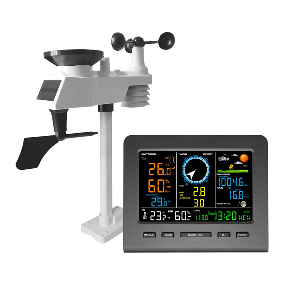
FT0366 Professional Wireless Weather Station
1. Introduction..........................................................................3
2. Warnings and Cautions........................................................3
3. Getting Started.....................................................................3
3.1 Parts List.........................................................................3
3.2 Recommend Tools.........................................................6
3.3 Sensor Assembly Set Up................................................6
3.3.1 Install Integrated Outdoor Sensor Battery............... .. . . . . . . . . . . . . . . 6
3.4 Display Console.......................................................... 10
3.4.1 Layout of Display Console. ..................................... 10
3.4.2 Set up the Display Console .....................................11
3.4.3 Connect Sensor with Display Console ....................1 3
3. 5 Sensor Operation Verification........................................13
4. Sensor Pre- Installation.....................................................14
4.1 Test the Sensor Before Installation..............................1 4
4.2 Site Survey Before Installation......................................14
4.3 Best Practices for Wireless Communication ..... ............1 5
5. Final Installation of Sensor ...............................................1 7
5.1 Integrated outdoor Sensor Installation..........................1 7
6. Low Battery Icon................................................................22
7. Display Console Operation................................................2 2
7.1 Quick Display Mode......................................................22
7.2 Set (Program) Mode....................................................2 3
7. 3 Se n s o r Se a r c h Mo de . .. . . . . . . . . . . . . . . . . . . . . . . . . . . . . . . . . . . . . . . . . . . . 2 5
7. 4 Max/Min Viewing and Re set Mode ...............................2 6
7.5 Snooze Mode...............................................................27
7.6 Backlight Mode.............................................................27
8. Alarm Mode........................................................................28
8.1 Alarm Triggered............................................................28
8.2 View High/Low Alarm Value. ........................................29
User Manual
1
Advertisement
Table of Contents

Related Manuals for Sainlogic FT0366


Summary of Contents for Sainlogic FT0366
-
Page 1: Table Of Contents
FT0366 Professional Wireless Weather Station User Manual 1. Introduction................3 2. Warnings and Cautions............3 3. Getting Started..............3 3.1 Parts List.................3 3.2 Recommend Tools............6 3.3 Sensor Assembly Set Up..........6 3.3.1 Install Integrated Outdoor Sensor Battery....... 6 3.4 Display Console............ -
Page 2: Introduction
8.3 Setting the Alarms............2 9 8.4 Alarm and Key Beeper ON/OFF ........3 1 9. Optional Calibration Mode...........31 9.1 Calibration of Temperature Mode........32 9.2 Calibration of Humidity Mode........3 3 9.3 Calibration of Sensors Mode.........34 10. Other Features of Display Console........38 10.1 Weather Forecasting..........3 8 10.2 Weather Icons............39 10.3 Moon Phase...............40 10 .4 Feels Like Temperature . -
Page 3: Warnings And Cautions
The following user guide provides step by step instructions for installation, operation and troubleshooting. 2.Warnings and Cautions Warning: Any metal object may attract a lightning strike, including your weather station mounting pole. Never install the weather station in a storm. Warning: Installing your weather station in a high location may result in injury or death. - Page 4 Item Image Integrated Outdoor Transmitter Dimensions: 13x11x5.9 inch (330x280x150mm) Foot Mounting (with pole insert) Dimensions: 4x3x1.5inch (101x76x37mm) Mounting Bracket Back Plate (pole mount) Dimensions: 3x2.96x0.79inch (76x75x20mm) Mounting Pole Dimensions: 11.8x1.18x0.79inch (300x30x20mm) Pole mounting nuts (M3) / bolts Ø3)
-
Page 5: Recommend Tools
Item Image Pole mounting nuts (M5) / bolts ( Ø5) Tapping screws Manual Power Adapter Figure 1 3.2 Recommend Tools Precision screwdriver (for small Phillips screws) Compass or GPS (for wind direction calibration) Adjustable Wrench . 3.3 Sensor Assembly Set Up... -
Page 6: Install Integrated Outdoor Sensor Battery
Note: The outdoor sensor array must be powered and updating before powering up the console, or the console will stop scanning and connecting with the sensors. The following illustration shows the full segment of integrated outdoor sensor , Wind and Rain, as shown in Figure 2. Figure 2 3.3. - Page 7 Note: Do not install the batteries backwards. You can permanently damage the outdoor sensors. The solar panel does not charge the batteries, so rechargeable batteries are not recommended. Figure 3 Remove the battery door on the back of the sensor by removing the set screw, as show in Figure 4.
- Page 8 Inserting 3 AA fresh batteries as show in Figure 5. Close the battery door. Make sure that the gasket (around the battery compartment) is properly seated in its trace prior to closing the door and Tighten the set screw. Note: We recommend installing Lithium AA batteries for outdoor sensors in cold weather environments The Integrated outdoor sensor LED indicator(White button) will light for 3 seconds, and then flash once per 16 seconds thereafter.
-
Page 9: Display Console
Figure 6 3.4 Display Console 3.4.1 Layout of Display Console The following illustration shows the segment of LCD display for feature description purposes only in Figure 7. Figure 7... -
Page 10: Setup The Display Console
1) Wind speed units of measure 20) Indoor humidity change 2) Wind gust display indication 3) Wind direction 21) Indoor humidity display 4) Wind gust hi alarm 22) Min/Max reset for 24h icon 5) Weather forecast 23) Indoor temperature display 6) Relative and absolute pressure 24) WIFI network 7) Pressure HI/LO alarm icon... - Page 11 BL ON will display in the time area for three seconds when powered up. Conversely, The AC OFF icon will display . Note: It is recommended to plug in the power adapter to reduce the battery consumption and extend the service life. 2.
-
Page 12: Connect Sensor With Display Console
Replace the battery door, and unfold out the desk stand to place the console in the upright position. Note: The battery is a back-up of weather station console, saving console settings when powered off from adaptor 3.4.3 Connect Sensor with Display Console Once the display console is powered up, it will automatically scan all the nearby Integrated Outdoor sensors. -
Page 13: Sensor Pre-Installation
The following steps verify proper operation of the sensors prior to install the sensor array. 1. Verify proper operation of the rain gauge. Tip the Integrated outdoor sensor back and forth several times. You will heard a “ticking” sound within the rain gauge. Verify the rain reading on the display console is not reading 0.00. -
Page 14: Best Practices For Wireless Communication
2. Avoid radiant heat transfer from buildings and structures. In general, install the sensor array at least 5ft (1.5m) from any building, structure, ground, or roof top. 3. Avoid wind and rain obstructions. The rule of thumb is to install the sensor array at least four times the distance of the height of the tallest obstruction. -
Page 15: Final Installation Of Sensor
4. Metal Barriers. Radio frequency will not pass through metal barriers such as aluminum siding. If you have metal siding, align the remote and console through a window to get a clear line of sight. The following is a table of reception loss vs. the transmission medium. Each “wall”or obstruction decreases the transmission range by the factor shown below. - Page 16 Southern Hemispheres 5.1.1 Northern Hemispheres (NOR) References. The cardinal directions (N, S, E, W) molded on the body of the outdoor sensor are indicators for the Northern Hemisphere only. Step 1: There is a “S” indicator on the wind vane that indicates South, as shown in Figure 14.
- Page 17 South North Figure 9 Step 2: Console operation set to Northern Hemispheres( NOR in the time area) in Location division. (Check the detailed step of setting the time area in the part 15 of Chapter 7.2) 5.1.2 Southern Hemispheres (SOU) References. For Southern Hemisphere installations, ignore the direction (N, S, E, W), and face the solar panel to the North (and in a sunny position) when it comes to install the Integrated outdoor sensor, as show in figure 10.
- Page 18 North South Figure 10 Step 2: Console operation set to Southern Hemispheres( SOU in the time area) in Location division. (Check the detailed step of setting the time area in the part 15 of Chapter 7.2) Note: The location division (NOR or SOU) on the Display Console and the directions of the sensor have to be adjusted to match with your real location.
- Page 19 Figure 11 5.1.4 Mounting & Fixing the Sensor Vertically...
-
Page 20: Low Battery Icon
Fasten the integrated outdoor sensor to the mounting pole brackets with foot-mounting,two Ø3 bolts and M3 nuts. Then, tighten the mounting pole to your existing mounting pole with the four bolts ( Ø5) and nuts (M5) , or fix it on the flat surface with four tapping screws, as show in Figure 12. -
Page 21: Display Console Operation
A low battery indicator icon is shown in the display window for integrated outdoor sensor. When the low battery icon appears (The Integrated outdoor sensor battery voltage is lower than 3.6V), replace the batteries in the sensor with fresh batteries. Be sure to never mix old and new batteries, and never mix battery types such as alkaline and lithium together. -
Page 22: Set (Program) Mode
To clear the total rain, press the CHANNEL/+ or MAX/MIN/- button until total rain is displayed. The total rain will flash. Press and hold the SET button for five seconds until total rain reads 0.0. 3. Absolute Pressure and Relative Pressure. Press the CHANNEL/+ or MAX/MIN/- key to toggle between absolute pressure and relative pressure. - Page 23 5. Change Month. Press the SET key again to set the calendar month. Press the CHANNEL/+ key or MAX/MIN/- key to adjust the calendar month. 6. Change Day. Press the SET key again to set the calendar day. Press the CHANNEL/+ key or MAX/MIN/- key to adjust the calendar day. 7.
-
Page 24: Se N S O R Se A R C H Mo
14. Weather Icons Setting (default: partly cloudy). Press the SET key again to change the initial weather icon. Press the CHANNEL/+ key or MAX/MIN/- key to select the initial weather icon of Sunny, Cloudy, Partly Cloudy or Rainy. (For detailed information of this part please refer to 10.2) 15. -
Page 25: Snooze Mode
Note: The Maximum values will display the current values after reset. 7.4.2 Min Record Viewing and Reset Press the MAX/MIN/- key again (do not hold), the MIN icon will be displayed. Press the SET key to view min values of pressure (ABS or REL), outdoor temperature and humidity (dew point or feels like), and indoor temperature and humidity. -
Page 26: Alarm Mode
2. When backlight is off, press and hold the SNOOZE/LIGHT key for three seconds, the backlight will turn on permanently, and BL ON icon will be displayed for three seconds in the date area. 3. To turn off the display backlight at any time, press and hold the SNOOZE/LIGHT key for two seconds. -
Page 27: View High/Low Alarm Value
8.2 View High/Low Alarm Value To view the current alarm settings, press the ALARM key to enter the alarm mode. HI AL 1 will be displayed in the date area. At the same time Alarm 1 time and HI alarm parameters of indoor temperature and humidity, outdoor temperature and humidity, outdoor feels like , 1h rainfall, absolute pressure, wind gust, wind average are displayed. - Page 28 Press the ALARM key to turn on (the alarm icon will appear ) and off the alarm. Press the SNOOZE/LIGHT key once at any time to return to the normal mode. After 30 seconds of inactivity, the alarm mode will time out and return to normal mode.
-
Page 29: Alarm And Key Beeper On/Off
60% and silence the alarm, the alarm icon will continue to flash until the humidity falls below 56%, at which point, the alarm will reset and must increase above 60% to activate again. 8.4 Alarm and Key Beeper ON/OFF Press any button to silence the alarm sound. In normal mode, press and hold the ALARM key for three seconds to toggle the BZ ON (beeper on) or BZ OFF (beeper off) depending on the current setting. -
Page 30: Calibration Of Temperature Mode
degradation errors. Do not compare your readings obtained from sources such as the internet, radio, television or newspapers. They are in a different location and typically update once per hour. The purpose of your weather station is to measure conditions of your surroundings, which vary significantly from location to location. -
Page 31: Calibration Of Sensors Mode
Press the CHANNEL/+ key or MAX/MIN/- key to increase or decrease the humidity reading (in increments of 1%). Press and hold the CHANNEL/+ key or MAX/MIN/- key for three seconds to increase or decrease rapidly. Press the ALARM key to reset current value. Press the SET key switch to outdoor humidity. - Page 32 Press and hold the CHANNEL/+ or MAX/MIN/- key for three seconds to increase or decrease rapidly. Press the ALARM key to reset current value. Example: The calibrated pressure sources measure 28.37 inHg. The display console pressure reads 28.75 inHg. Offset = 28.37 - 28.75 = - 0.38 inHg ...
- Page 33 pressure (the pressure your location would be at if located at sea-level) is generally higher than your measured pressure. Thus, your absolute pressure may read 28.62 inHg (969 mb) at an altitude of 1000 feet (305 m), but the relative pressure is 30.00 inHg (1016 mb). The standard sea-level pressure is 29.92 in Hg (1013.2hpa).
- Page 34 Note: The wind gust is also affected by the wind speed calibration factor. Discussion: Wind speed and wind gust are adversely affected by installation constraints. The rule of thumb is to install the weather station four times the distance of the height of the tallest obstruction (for example, a 6m(20ft) house would require an installation 24m(80ft) away).
-
Page 35: Other Features Of Display Console
Discussion: The rain collector is calibrated at the factory based on the funnel diameter. The bucket tips every 0.01” of rain (referred to as resolution). The accumulated rainfall can be compared to a sight glass rain gauge with an aperture of at least 4”. Note: that debris and insects can collect inside the tipping mechanism (they make a good spiders nest). -
Page 36: Moon Phase
Pressure is falling and the previous Partly condition is sunny or Cloudy Pressure is rising and the previous condition is cloudy Pressure is falling and the previous condition is partly Cloudy cloudy or Pressure is rising and the previous condition is rainy. -
Page 37: Feels Like Temperature
10.4 Feels Like Temperature 10.4.1 Feels Like Temperature Feels like temperature is a combination of Heat Index and Wind Chill. 1. Temperatures less than 4.4°C(40°F), the wind chill is displayed, as shown in the National Weather Service Wind Chill Table below:... -
Page 38: Pressure Threshold Setting
2. Temperatures greater than 26.7°C(80°F), the heat index is displayed, as shown in the National Weather Service Heat Index Table below: 10.5 Pressure Threshold Setting The pressure threshold (the negative or positive rate of change of pressure signifying a change in the weather) can be adjusted from 2 hPa to 4 hPa (default level 2 hPa). - Page 39 Clean the rain gauge of Integrated Outdoor Transmitter once every 3 months. Unscrew the rain collector funnel by turning it 30°counter clockwise. Gently remove the rain collector funnel. Clean and remove any debris or insects. Install the collector funnel after it has been cleaned and completely dried.
-
Page 40: Trouble Shooting Guide
B.Install the collector funnel. Replace the Integrated outdoor sensor batteries once every 1-2 years. 12. Trouble Shooting Guide... - Page 41 Problem Solution Wireless remote If any of the sensor communication is lost, dashes reporting in to console. (--.-) will be displayed on the screen. To reacquire the signal, press and hold the CHANNEL/+ button There are dashes (--.-) on for 3 seconds, the remote search icon will be the display console.
-
Page 42: Specifications
the remote sensor to a closer location. Indoor Outdoor Allow up to one hour for the sensors to stabilize due Temperature do not agree signal filtering. indoor outdoor temperature sensors should agree within 2°C/4°F) (the sensor accuracy is ± 1°C/2°F). Use the calibration feature to match the indoor and outdoor temperature to a known source. - Page 43 Indoor Humidity 10 to 99 % ± 5% (only guaranteed between 20 to 90%) Outdoor Humidity 10 to 99% ± 5% (only guaranteed between 20 to 90%) Rain 0 to 9999mm <15mm: <1000mm ±1 mm, (0.3mm) 15mm to >1000mm 9999mm: (1mm) ±7% Wind Direction...
- Page 44 Note: Solar panel doesn't charge the battery and it is an auxiliary power supply Adapter: 5.9V~500mA(included) Battery life: Minimum 12 months for base station with excellent reception. Intermittent reception may reduce the battery life. Minimum 12 months for sensors (use lithium batteries in cold weather climates less than -20°C(-4°F).
Need help?
Do you have a question about the FT0366 and is the answer not in the manual?
Questions and answers