Table of Contents
Advertisement
FT-0310
1.Introduction
Thank you for your purchase of the FT0310
The following user guide provides step by step instructions for installation, operation, and
troubleshooting.
2.Warnings
Warning: Any metal object may attract a lightning strike, including your weather sta-
tion mounting pole. Never install the weather station in a storm.
Warning: Installing your weather station in a high location may result in injury or
death. Perform as much of the initial check out and operation.
3.Getting Started
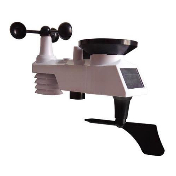
The FT0310 weather station consists of a display console (receiver), a sensor array with
Integrated Outdoor Transmitter and mounting hardware.
Parts List
The FT0310 weather station consists of the following parts (as referenced in Figure 1 ).
QTY
Display Console
Frame Dimensions (Lx H x W):
1
215X22X158mm
LCD Dimensions (L x W): 170 x 125mm
Integrated Outdoor Transmitter
1
Dimensions (L x H x W):
330x150x280mm
Professional WIFI Weather Station
User Manual
Professional WIFI Wireless Weather
Item
1
station.
Image
Advertisement
Table of Contents

Related Manuals for Sainlogic FT-0310


Summary of Contents for Sainlogic FT-0310
- Page 1 FT-0310 Professional WIFI Weather Station User Manual 1.Introduction Thank you for your purchase of the FT0310 Professional WIFI Wireless Weather station. The following user guide provides step by step instructions for installation, operation, and troubleshooting. 2.Warnings Warning: Any metal object may attract a lightning strike, including your weather sta- tion mounting pole.
- Page 2 Item Image Foot Mounting (with pole insert) Dimensions: 84x 152 x 216mm Mounting Bracket Back Plate (pole mount) Dimensions: 76 x 102 x 38mm Mounting Pole Dimensions: 76 x 76 x 25mm Pole mounting nuts (M3) / bolts Ø3) Pole mounting nuts (M5) / bolts ( Ø5) Tapping screws Manual...
-
Page 3: Recommend Tools
Item Image Power Adapter Figure 1 3.2 Recommend Tools ● Precision screwdriver (for small Phillips screws) ● Compass or GPS (for wind direction calibration) ● Adjustable Wrench 3.3 Sensor Assembly Set Up The following illustration shows the full segment for Thermo-Hygrometer,WIND,RAIN and UV INDEX sensor .(Display purposes only), as shown in Figure 2. - Page 4 Figure 3 Remove the battery door on the back of the sensor by removing the set screw, as shown in Figure 4. Figure 4 Inserting 3xAA batteries in the battery compartment, as show in Figure 5.
- Page 5 Figure 5 Close the battery door. Make sure the gasket (around the battery compartment) is properly seated in its trace prior to closing the door. Tighten the set screw. Note: Do not install the batteries backwards. You can permanently damage the sensors. The solar panel does not charge the batteries, so rechargeable batteries are not needed or recommended.
-
Page 6: Display Console Set Up
Figure 6 3.4 Display Console 3.4.1 Display Console Layout The display console layout is shown in Figure 10 Note: The following illustration shows the full segment LCD display for description purposes only and will not appear like this during normal operation. Figure 10 1. - Page 7 It is recommended to plug in the power supply to reduce the battery consumption and extend the service life. Note: The sensor array must be powered and updating before powering up the console, or the console will time out searching for the sensor. Power the console last. Make certain the weather station sensor array is at least 3m away from the console and within 30m of the console.
-
Page 8: Weather Station Installation
mounted position. The prongs are not designed to hold the plug-in place if it is plugged in- to a ceiling, under-the-table or cabinet outlet. Figure 12 Note: If the power adapter is plugged in, BL ON will display in the time area for three seconds when powered up. -
Page 9: Best Practices For Wireless Communication
4.3 Best Practices for Wireless Communication Wireless communication is susceptible to interference, distance, walls, and metal barriers. We recommend the following best practices for trouble free wireless communication. 1. Electro-Magnetic Interference (EMI). Keep the console several feet away from com- puter monitors and TVs. - Page 10 Note:There are four alphabet letter of “N”,”E”,”S”and “W” around the wind direction, representing for the direction of North, East, South and West. Wind direction sensor has to be adjusted so that the directions on the sensor are matching with your real location. Per- manent wind direction error will be introduced when the wind direction sensor is not posi- tioned correctly during installation.
- Page 11 Fasten the integrated transmitter to mounting pole brackets with foot-mounting, two ¢3 bolts and M3 nuts , as shown in Figure 14 Figure 14 Tighten the mounting pole to your existing mounting pole with the four¢5 Bolts and M5 Nuts assembly, or fix on the wall with four tapping screw, as shown in Figure15.
-
Page 12: Low Battery Icon
Figure 15 Low Battery Icon. A low battery indicator icon is shown in the display window for Integrated outdoor trans- mitter. When the low battery icon appears (the battery voltage is lower than 3.6V), replace... -
Page 13: Console Operation
the batteries in the sensor with fresh batteries. Be sure to never mix old and new batteries, and never mix battery types such as alkaline and lithium together. 7.Console Operation Note: The console has five keys for easy operation: MIN/MAX/-key, ALARM key, SET/MODE key, CHANNEL/+ and SNOOZE key. -
Page 14: Reset Min/Max Record
4. Change Minute. Press the SET(MODE) key again to set the minute. Press the [+] key or [-] key to adjust the minute up or down. 5. Date Format (default: MM-DD): Press the SET(MODE) key again to enter the day/month format mode. Press the [+] key to switch between MM-DD, DD-MM. 6. -
Page 15: Back Light Mode
Press the MIN/MAX/- key for three seconds to clear all max values. (the rainfall, wind speed, wind gust, pressure, temperature and humidity maximum values. The maximum values will now display the current values). Press the MIN/MAX/- key again (do not hold), the MIN icon will be displayed. Press the SET/ MODE key to view min values of pressure (ABS or REL), outdoor tempera- ture/humidity((AT or dew point),and indoor temperature/humidity(temp or dew point). -
Page 16: Alarm Operation
• Wind Gust • Wind Average • Rate Rainfall • 24 Hour Rainfall • Absolute Pressure • Relative Pressure • Indoor Temperature • Indoor Humidity • Indoor Dew Point • UV Index • Sunlight 8.1 Alarm Operation When an alarm condition is exceeded, the alarm icon will flash (visual) and the alarm beeper will sound (audible). -
Page 17: Alarm And Command Key Beeper On/Off Mode
2. Alarm minute(alarm 1) 3. Alarm hour(alarm 2) 4. Alarm minute(alarm 2) 5. Outdoor temperature high alarm 6. Outdoor temperature low alarm 7. Outdoor humidity high alarm 8. Outdoor humidity low alarm 9. Outdoor AT high alarm 10. Outdoor AT low alarm 11. -
Page 18: Wifi Connection Status
9.WiFi Connection Status When the console successfully connects to your Wi-Fi router, the Wi-Fi signal icon will appear on the LCD display(behind the Outdoor humidity). If the Wi-Fi signal is not stable or the console is trying to connect to the router, the icon will flash. If the icon disap- pears, it means the console is not connected to the Wi-Fi router. - Page 19 Figure 18 3) As shown below, an email will be received in your registered mailbox . Figure 19 4) As shown below, open your mail and log in to the Web address in the mail. Figure 20 5) As shown below, click “here” to enter the homepage of the weathercloud website.
- Page 20 Figure 21 6) As shown below, enter the email address and password you just registered to enter the weathercloud website. Figure 22 11.2 Add a weather station device (it may take a few minutes).
- Page 21 Figure 23 1) After sign up you will be prompted to add a device/ Select “Create device” and enter your station’s information: Blanks with red * must be filled in. Figure 24 Note: You can select any Model number and Link type in the above blanks. 2) As shown below, click Get coordinates to identify your location of on the map, then click Done to confirm..
-
Page 22: Register At Wunderground.com (Weather Underground)
3) As shown below, click Create. Figure 26 4) As shown below, after registering successfully, please record the Weathercloud ID and Key information for later use. (Refer to 13.6) Figure 27 12. Register at Wunderground.com (Weather Underground) Note: The Weather Underground website is subject to change. Visit: , and select the Join link in the upper right and corner and https://Wunderground.com... - Page 23 Figure 28 2) As shown below, enter a Username, Email and Password(It is your Login password of the websiteIt, not your email password.So no privacy will be exposed). Click Sign up for free. Figure 29 3) As shown below, registration is done successfully.
- Page 24 Figure 30 4) As shown below, click Log in and enter the email address and password you just registered. Figure 31 5) As shown in the below, click My Profile. Then enter Member Settings. Figure 32 6) As shown below, click Update home location.
- Page 25 Figure 33 7) As shown below, you will then be prompted to add a device/ Select “Add New Device Figure 34 8) As shown below, click Personal Weather Station. Figure 35 9) As shown below, select Address by inputting an address or select Manual to position your address automatically.
- Page 26 Figure 36 10) As shown below, you will then be prompted to add a device/ Select “Create de- vice” , then click I Accept and Next: Blanks with red (Required) must be filled in. Note: You can select any wifi weather station model in Device Hardware blank.
- Page 27 Figure 37 11) As shown below, after registering the host successfully, please record Station ID and Station Key information for later use (refer to 13.6). Figure 38 12) As shown below, registration is done successfully.
- Page 28 Figure 39 13.WiFi Setup(Connect your Device to the Console’s WiFi) When you first power up(AC) the console, or press and hold the MIN/MAX/- button for three seconds in normal mode, the console icon(behind the Outdoor humidity)) will flash to signify that it has entered WAP (wireless access point) mode, and is ready to enter for WIFI settings.
- Page 29 Choose the Settings icon Network . Connect to the WeatherHome------ WiFi network, as shown in Figure 41 (your WiFi network name may be slightly different, but will always begin with WeatherHome------ ). Figure 41 13.3: Example 3. Connect to the console WiFi server with an iPhone or iPad. Choose the Settings icon and Wi-Fi.
- Page 30 From the Apps icon, choose the Settings icon and Wi-Fi. Connect to the Weather- Home------ WiFi network, as shown in Figure 43 (your WiFi network name may be slight- ly different, but will always begin with WeatherHome------ ). Figure 43 13.5.
- Page 31 Figure 44 Notes: Hidden SSIDs. If you have a hidden SSID, enter the SSID manually. Time Zone Settings(default: 0h). based on the number of hours from Coordinated Uni- versal Time, or Greenwich Mean Time (GMT). The following table provides times zones throughout the world. Locations in the eastern hemisphere are positive, and locations in the western hemisphere are negative.
- Page 32 Hours from Time Zone Cities -12 IDLW: International Date Line West -11 NT: Nome Nome, AK -10 AHST: Alaska-Hawaii Standard Honolulu, HI CAT: Central Alaska HST: Hawaii Standard -9 YST: Yukon Standard Yukon Territory -8 PST: Pacific Standard Los Angeles, CA, USA -7 MST: Mountain Standard Denver, CO, USA -6 CST: Central Standard...
- Page 33 Hours from Time Zone Cities 12 IDLE: International Date Line East Wellington, New Zealand NZST: New Zealand Standard 13.7. If all of the information you entered is correct press save to confirm(Figure 45). If it does not, check your web interface information again. Figure 45 13.8.
-
Page 34: Upgrade Firmware
13.9 Viewing your Data on Weather Underground Visit:http://www.wunderground.com/personal-weather- station/dashboard?ID=STATIONID where STATIONID is your personal station ID (example, KCALOSAN782). Figure 47 Multiple Sensor Features Wunderground.com does not support multiple sensor channels. Note: The current temperature and humidity data is the Integrated Outdoor Transmitter. 13.10. -
Page 35: Other Console Features
Figure 49 14.5. Press Select File key to select the upgraded firmware as figure 50. Figure 50 14.6. If update successfully when press Upgrade key. Then you will see. Figure 51 NOTE: In this upgrade only Wifi firmware is updated. The console does not reset. 14.7.Once the upgrade is completed, the console will automatically exit WAP mode. -
Page 36: Weather Forecasting
15.1 Weather Forecasting Note: The weather forecast or pressure tendency is based on the rate of change of bar- ometric pressure. In general, when the pressure increases, the weather improves (sunny to partly cloudy) and when the pressure decreases, the weather degrades (cloudy to rain). The weather forecast is an estimation or generalization of weather changes in the next 24 to 48 hours, and varies from location to location. - Page 37 15.4 Feels Like Temperature and AT Feels like temperature is a combination of Heat Index and Wind Chill. At temperatures less than 4.4C(40° F), the wind chill is displayed, as shown in the National Weather Service Wind Chill Table below: Figure 17 At temperatures greater than 26.7C(80°...
-
Page 38: Pressure Threshold Setting
Figure 18 When the temperature is between 4.4C (40° F) and 26.7C (80° F), the OUT temperature is displayed (Feels Like temperature is the same as OUT temperature). The concept of apparent temperature (AT) is a linear regression that is not restricted, and is more appropriate to outside conditions because it includes wind. -
Page 39: Measurement Specifications
16.2 Measurement Specifications The following table provides specifications for the measured parameters. Measurement Range Accuracy Resolution Indoor Temperature 0 to 60 ° C ± 1 ° C 0.1 ° C Outdoor Temperature -40 to 60 ° C ± 1 ° C 0.1 °... -
Page 40: Maintenance
device, including laptops, computers, smart phones and smart pads. 4. Recommend web browser for setup UI: Web browser support of HTML 5, such as the latest versions of Chrome, Safari, IE, Edge, Firefox or Opera. 5. Line of sight WiFi RF transmission (in open air): 20meter (80 feet) 17.Maintenance 1.Clean the rain gauge of Integrated Outdoor Transmitter once every 3 months. -
Page 41: Troubleshooting Guide
Figure 52 2. Replace the Integrated and thermo-hygrometer transmitter batteries once every 1-2 years Troubleshooting Guide. Problem Solution Wireless remote not reporting in to con- If any of the sensor communication is lost, dashes (--.-) sole. will be displayed on the screen. To reacquire the signal, press and hold the CHANNEL/+ button for 3 seconds, There are dashes (--.-) on the display con- choose the lost sensor and the remote search icon... - Page 42 Problem Solution Indoor and Outdoor Humidity do not agree Allow up to one hour for the sensors to stabilize due to signal filtering. The indoor and outdoor humidity sensors should agree within 10 % (the sensor accuracy is ± 5 %). Use the calibration feature to match the indoor and out- door humidity to a known source.
- Page 43 Problem Solution Data not reporting to 1. Confirm your password or key is cor- www.wunderground. rect. It is the password you registered on Wunderground.com. Your Wunder- or www.weathercloud.net ground.com password cannot begin with a non-alphanumeric character (a limitation of Wundeground.com, not the station). Example, $worknet is not a valid pass- word, but worknet$ is valid.
Need help?
Do you have a question about the FT-0310 and is the answer not in the manual?
Questions and answers
Top left outdoor temperature showing dashes. Have reset everything and added new batteries etc but still no good. However bottom right is working on ch 1.
The top left outdoor temperature on the Sainlogic FT-0310 may display dashes due to signal issues between the remote sensor and the display console. Possible reasons include:
1. The remote sensor is too far from the display console.
2. There is interference from electrical devices like computers or TVs.
3. The sensor needs time to stabilize (up to one hour).
4. The sensor is not positioned properly (e.g., blocked by obstacles).
Solutions:
- Move the sensor closer to the console.
- Reduce interference from electronic devices.
- Allow time for the sensor to stabilize.
- Ensure the sensor has fresh batteries.
This answer is automatically generated