Advertisement
Quick Links
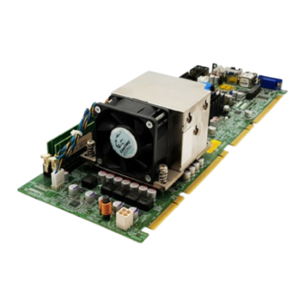
Full-size PICMG 1.3 CPU Card supports LGA1155 Intel®
Xeon® E3 and Intel® Core™ i3 CPU per Intel® C206, DDR3,
VGA/DVI-D, Dual Intel® PCIe GbE, SATA 6Gb/s, mini PCIe,
Quick Installation Guide
Package Contents
SPCIE-C2060 package includes the following items:
1 x SPCIE-C2060 Single Board Computer
1 x Dual RS-232 Cable (P/N:19800-000051-RS)
4 x SATA Cable (P/N:32000-0628000-RS)
1 x USB Cable (P/N: CB-USB02-RS)
1 x DVI and USB Kit (P/N:IO-KIT-001-R20)( DVI SKU only)
1 x Mini Jumper Pack
1 x Utility CD
1 x QIG (Quick Installation Guide)
©2006 Copyright by IEI Technology corp.
Audio and RoHS
SPCIE-C2060
Version 1.01
Nev. 10, 2011
All rights reserved.
1
Advertisement

Subscribe to Our Youtube Channel
Related Manuals for IEI Technology SPCIE-C2060


Summary of Contents for IEI Technology SPCIE-C2060
- Page 1 SPCIE-C2060 Quick Installation Guide Version 1.01 Nev. 10, 2011 Package Contents SPCIE-C2060 package includes the following items: 1 x SPCIE-C2060 Single Board Computer 1 x Dual RS-232 Cable (P/N:19800-000051-RS) 4 x SATA Cable (P/N:32000-0628000-RS) 1 x USB Cable (P/N: CB-USB02-RS)
- Page 2 Specifications LGA1155 socket supports Intel® Xeon® E3/ Core™ i3 Quad/ Dual core processor System Chipset: Intel® C206 BIOS: UEFI BIOS System Memory: Two 240-pin 1066/1333MHz Dual-Channel DDR3 SDRAM ECC and non-ECC Unbuffered DIMM supported (system max.16GB) Graphic: VGA Integrated in Intel® C206 Display Output: 1 x VGA 1 x DVI-D (DVI SKU only)
- Page 3 Dimensions: 338mm X 126mm Weight: 1.2Kg Ordering Information SPCIE-C2060-R10: Full size PICMG 1.3 CPU Card supports 32nm LGA1155 Intel® Xeon® and Intel® Core™ i7/i5/i3 CPU per Intel® C206, DDR3, Dual Intel® PCIe GbE, 2 SATA III, mini PCIe, Audio and RoHS SPCIE-C2060-DVI-R10: Full size PICMG 1.3 CPU Card supports 32nm...
- Page 4 CF-1156B-RS: High-performance LGA1155/LGA1156 cooler kit, 95W CF-1156C-RS: LGA1155/LGA1156 cooler kit, 1U chassis compatible, CF-1156D-RS: LGA1155/LGA1156 cooler kit, 1U chassis compatible,...
- Page 5 Jumpers setting and Connectors Table of Jumpers LABEL FUNCTION J_CMOS1 CMOS state setting WOL_SEL1 WOL Enable setting JATX_AT1 Power Mode Setting Table of Connectors LABEL FUNCTION VGA1 VGA 15-pin Female Connector USB_C1 USB Port Connector USB_C2 LAN1 、 LAN2 RJ45 LAN Connector KB_MS1 Internal PS/2 KEYBOARD/MOUSE Connector COM1...
- Page 6 J_CMOS1 : Clear CMOS setting Jumper J_CMOS1 DESCRIPTION Normal (Default) Clear CMOS Data JATX_AT1 : Power Mode Setting by ATX or AT JATX_AT1 DESCRIPTION ATX Power Mode (ON) AT Power Mode (OFF) VGA1 : 15-pin Female Connector DESCRIPTION DESCRIPTION GREEN BLUE DDCDAT HSYNC...
- Page 7 MS/KB1: Internal 6-pin Keyboard Connector DESCRIPTION VCC(+5V) Mouse Data Mouse Clock Keyboard Data Keyboard Clock Ground COM1,COM2: Internal Serial Port Connector DESCRIPTION DESCRIPTION DCD# DSR# RTS# CTS# DTR# USB1-USB6: Internal USB Connector PIN DESCRIPTION DESCRIPTION DATA- DATA+ DATA+ DATA- J_AUDIO1 : External Audio Module Connector PIN DESCRIPTION DESCRIPTION ACZ_BITCLK...
-
Page 8: Table Of Contents
SATA1-SATA6 : Serial ATA Connector DESCRIPTION DESCRIPTION IR1: IrDA connector PIN NO. DESCRIPTION IR-RX IR-TX FDD1: Floppy Disk Drive Connector DESCRIPTION DESCRIPTION REDUCE WRITE INDEX# MOTOR ENABLE A# DRIVE SELECT B# DRIVE SELECT A# MOTOR ENABLE B# DIRECTION# STEP# WRITE DATA# WRITE GATE# TRACK 0# WRITE PROTECT#... -
Page 9: Pin Description Pin
LPT1 : Parallel Port Connector DESCRIPTION DESCRIPTION STROBE# AUTO FORM FEED # DATA0 ERROR# DATA1 INITIALIZE# PRINTER SELECT DATA2 DATA3 DATA4 DATA5 DATA6 DATA7 ACKNOWLEDGE# BUSY PAPER EMPTY PRINTER SELECT DVI Connector (DVI SKU only) PIN NO. DESCRIPTION PIN NO. DESCRIPTION Data 2- Data 2+... -
Page 10: Gnd
CPU_FAN1 : CPU Fan Connector PIN NO. DESCRIPTION Ground +12V Rotation Signal Control DIO1 : Digital Input / Output Connector PIN NO. DESCRIPTION PIN NO. DESCRIPTION Ground Output 3 Output 2 Output 1 Output 0 Input 3 Input 2 Input 1 Input 0 F_PANEL1 : External Switches and Indicators panel PIN DESCRIPTION PIN DESCRIPTION... -
Page 11: Gnd
MINI-PCIE1 : PCI-E Mini Card Connector PIN NO. DESCRIPTION PIN NO. DESCRIPTION PCIE_WAKE# VCC3 1.5V CLKREQ# LFRAME# LAD3 CLK- LAD2 CLK+ LAD1 LAD0 PCIRST# VCC3 PCIRST# PERN2 3VDual PERP2 1.5V SMBCLK PETN2 SMBDATA PETP2 USBD- USBD+ RF_LINK# BLUELED# 1.5V VCC3 I2C_1 PIN NO. -
Page 12: Gnd
SMBUS Connector PIN NO. DESCRIPTION SMB_DATA SMB_CLK +V5S TPM1 Connector PIN NO. DESCRIPTION PIN NO. DESCRIPTION FRAME# RERST# SMB_CLK SMB_DATA SB3V SERIRQ CLKRUN# PM_SUS_STAT# DRQ# COM4 : Internal Serial Port Connector (RS422/485) PIN NO. DESCRIPTION RXD485# RXD485+ RXD485- RXD485# RS422/485 RS422 Pin define RS485 Pin define TX-(TXD485#) - Page 13 Board Layout: Jumper and Connector Locations...
Need help?
Do you have a question about the SPCIE-C2060 and is the answer not in the manual?
Questions and answers