IEI Technology TANK-XM811 Series User Manual
Embedded system with 10th/11th generation intel core processor, two ddr4 slot, digital i/o, hdmi, dp, two gigabit ethernet, rs-232/422/485, rohs compliant
Hide thumbs
Also See for TANK-XM811 Series:
- Quick start manual (2 pages) ,
- Quick start manual (2 pages)

Related Manuals for IEI Technology TANK-XM811 Series


Summary of Contents for IEI Technology TANK-XM811 Series
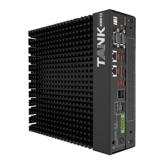
- Page 1 MODEL: TANK-XM811 Series Embedded System with 10th/11th Generation Intel® Core™ Processor, Two DDR4 Slot, Digital I/O, HDMI, DP, Two Gigabit Ethernet, RS-232/422/485, RoHS Compliant User Manual Rev. 1.00 – July 18, 2022...
- Page 2 TANK-XM811 Revisions Date Version Changes July 18, 2022 1.00 Initial release Page II...
- Page 3 TANK-XM811 Copyright COPYRIGHT NOTICE The information in this document is subject to change without prior notice in order to improve reliability, design and function and does not represent a commitment on the part of the manufacturer. In no event will the manufacturer be liable for direct, indirect, special, incidental, or consequential damages arising out of the use or inability to use the product or documentation, even if advised of the possibility of such damages.
- Page 4 TANK-XM811 Manual Conventions WARNING Warnings appear where overlooked details may cause damage to the equipment or result in personal injury. Warnings should be taken seriously. CAUTION Cautionary messages should be heeded to help reduce the chance of losing data or damaging the product. NOTE These messages inform the reader of essential but non-critical information.
-
Page 5: Table Of Contents
TANK-XM811 Table of Contents 1 INTRODUCTION ......................1 1.1 O ........................2 VERVIEW 1.2 M ....................3 ODEL ARIATIONS 1.3 F ........................3 EATURES 1.4 T ..................4 ECHNICAL PECIFICATIONS 1.5 F ......................6 RONT ANEL 1.6 R ....................... 7 ANEL 1.7 P .................... - Page 6 TANK-XM811 3.9.5 LAN Connectors ....................28 3.9.6 Power Input, 4-pin Terminal Block ..............30 3.9.7 Power Input, 4-pin DIN Connector ..............30 3.9.8 DB-9 RS-232/422/485 Serial Port Connectors ..........31 3.9.9 Remote Power Connector ................31 3.10 P ................32 OWERING FF THE YSTEM...
- Page 7 TANK-XM811 B.2.2 Cleaning Tools ....................56 C ERROR BEEP CODE ....................57 C.1 PEI B ..................... 58 ODES C.2 DXE B ....................58 ODES D HAZARDOUS MATERIALS DISCLOSURE ............59 D.1 R HS II D (2015/863/EU) ............... 60 IRECTIVE D.2 C HS ......................
- Page 8 TANK-XM811 List of Figures Figure 1-1: TANK-XM811 Series ....................2 Figure 1-2: Front Panel ........................6 Figure 1-3: Rear Panel ........................7 Figure 1-4: Physical Dimensions ....................8 Figure 3-1: Remove the Cover .....................18 Figure 3-2: Motherboard Removal ....................18 Figure 3-3: CPU Installation ......................19 Figure 3-4: CPU Thermal Pad Installation ..................19...
- Page 9 TANK-XM811 Figure 4-2: System Motherboard (Rear) ..................41 Figure 4-3: Ethernet Connector ....................45 Page IX...
- Page 10 TANK-XM811 List of Tables Table 1-1: TANK-XM811 Series Model Variations ............... 3 Table 1-2: Technical Specifications ....................5 Table 3-1: Digital I/O Connector Pinouts ..................27 Table 3-2: RJ-45 Ethernet Connector LEDs ................29 Table 3-3: RS-232 (COM1~COM4) & RS-232/422/485 (COM5~COM6) Connector Pinouts ..31 Table 3-4: Power LED Indicators Description ................34...
-
Page 11: Introduction
TANK-XM811 Chapter Introduction Page 1... -
Page 12: Overview
260-pin DDR4 SDRAM SO-DIMM slots supporting up to 64GB memory (8GB preinstalled). The TANK-XM811 Series includes one digital I/O port, one HDMI, one DP, two GbE LAN, eight USB 3.2 Gen 2, two RS-232/422/485 and four RS-232 connectors. -
Page 13: Model Variations
TANK-XM811 1.2 Model Variations The model variations of the TANK-XM811 Series are listed below. Model No. Intel® Core™ i5-12500TE 1.9GHz TANK-XM811-i5AC-R10 (up to 4.3GHz, 6-core, TDP 35W) Intel® Core™ i7-12700TE 1.4GHz TANK-XM811-i7AC-R10 (up to 4.6GHz, 12-core, TDP 35W) Intel® Core™ i9-12900TE 1.1GHz TANK-XM811-i9D-R10 (up to 4.8GHz, 16-core, TDP35W) -
Page 14: Technical Specifications
TANK-XM811 1.4 Technical Specifications The TANK-XM811 Series technical specifications are listed in Table 1-2 Specifications Chassis Color Black C Dimensions (WxDxH) (mm) 230.6 x 256.04 x 76.2 System Fan Fanless Chassis Construction Extruded aluminum alloy Motherboard 12th Gen. Intel® Core™ CPU: Intel®... -
Page 15: Table 1-2: Technical Specifications
TANK-XM811 Specifications 1 x 2280 M key (PCIe x4) 1 x 2230 A-key (USB+PCIe x1, supports vPRO) Backplane Optional Power DC jack: 12 V~28 V DC Power Input Terminal block: 12 V~28 V DC Power Consumption 12V @ 8.8A (Intel ® Core™ i9-12900TE with 16GB memory) Remote Power 1 x 2-pin Reliability... -
Page 16: Front Panel
TANK-XM811 1.5 Front Panel The front panel of the TANK-XM811 Series has the following features (Figure 1-2): Figure 1-2: Front Panel Page 6... -
Page 17: Rear Panel
TANK-XM811 1.6 Rear Panel The rear panel of the TANK-XM811 Series is shown below. Figure 1-3: Rear Panel Page 7... -
Page 18: Physical Dimensions
TANK-XM811 1.7 Physical Dimensions The physical dimensions of the TANK-XM811 are shown in Figure 1-4. 507H Figure 1-4: Physical Dimensions Page 8... -
Page 19: Unpacking
TANK-XM811 Chapter Unpacking Page 9... -
Page 20: Anti-Static Precautions
Electrostatic discharge (ESD) can cause serious damage to electronic components, including the TANK-XM811 Series. Dry climates are especially susceptible to ESD. It is therefore critical that whenever the TANK-XM811 Series or any other electrical component is handled, the following anti-static precautions are strictly adhered to. -
Page 21: Unpacking Checklist
If some of the components listed in the checklist below are missing, please do not proceed with the installation. Contact the IEI reseller or vendor you purchased the TANK-XM811 Series from or contact an IEI sales representative directly. To contact an IEI sales representative, please send an email to sales@ieiworld.com. - Page 22 TANK-XM811 Quantity Item and Part Number Image Standard 2-pin terminal block 4-pin terminal block Chassis screws The following table lists the optional items that can be purchased separately. Optional Wi-Fi module (P/N: EMB-WIFI-KIT02I3-R10) Page 12...
- Page 23 TANK-XM811 Optional Power adapter (P/N: 63040-010180-200-RS) Power cord (P/N: 32000-000002-RS) 8-Port POE LAN card (P/N: GPOE-XM81-8P-R10) M.2 & PCIe mini expansion card (P/N: GPOE-XM81-8P-R10) 2-slot backplane (PCIe x16 & PCIe x4) (P/N: TXCBP-XM81-2A-R10) 2-slot backplane (two PCIe x8) (P/N: TXCBP-XM81-2B-R10)ss Page 13...
- Page 24 TANK-XM811 Optional 4-slot backplane (PCIe x16 & two PCIe x4 & PCIe x1) (P/N: TXCBP-XM81-4A-R10) 4-slot backplane (two PCIe x8 & two PCIe x4) (P/N: TXCBP-XM81-4B-R10) 4-slot backplane (PCIe x16 & PCIe x4 & two PCI) (P/N: TXCBP-XM81-4C-R10) 4-slot backplane (PCIe x16 & two PCIe x4 & PCIe x1) (P/N: TXCBP-XM81-G1-PW-R10) 4-slot backplane (two PCIe x8 &...
- Page 25 TANK-XM811 Optional 3-slot chassis (P/N: TXC-XM81-3S-R10) 4-slot chassis (P/N: TXC-XM81-4S-R10) 4-slot chassis (full-length graphics card support) (P/N: TXC-XM81-G1-R10) 6-slot chassis (two full-length graphics card support) (P/N: TXC-XM81-G2-R10) Expansion fan module (P/N: SF-TANK-XM81-R10) NOTE: 1.TXCBP-XM81 series backplane needs to be used with TXC-XM81 series chassis Page 15...
-
Page 26: Installation
TANK-XM811 Chapter Installation Page 16... -
Page 27: Installation Precautions
Electric shock and personal injury might occur if the rear panel of the TANK-XM811 Series is opened while the power cord is still connected to an electrical outlet. -
Page 28: Cpu Installation
TANK-XM811 from the TANK-XM811. Follow the steps below to complete the task. Step 1: Turn the TANK-XM811 over and remove the 6 screws on the back cover. Step 2: Take off the back cover (Figure 3-1). Figure 3-1: Remove the Cover 3.3 CPU Installation To replace the CPU, you need to remove the motherboard first. -
Page 29: Figure 3-3: Cpu Installation
TANK-XM811 Figure 3-3: CPU Installation Step 3: Place a thermal pad on the heat conductive block of CPU (Figure 3-4). Figure 3-4: CPU Thermal Pad Installation Step 4: Align the motherboard (together with the motherboard holder) with the 4 positioning rods on the 2 sides, place it on the heat sink, and lock the motherboard with 11 spring screws. -
Page 30: Memory Installation
TANK-XM811 Figure 3-5: Motherboard Installation 3.4 Memory Installation TANK-XM811 pre-installed with 8GB or 16GB memory module. Users or replace memory with different capacity themselves, the installation procedures are described below. Step 1: Open the two handles of the memory slot. Step 2: Remove the old memory module and insert a new memory module. -
Page 31: Storage Installation
TANK-XM811 Figure 3-6: Memory Installation 3.5 Storage Installation The TANK-XM811 supports two types of storage, one M.2 M Key & one 2.5" SSD 3.5.1 M.2 SSD Installation Remove the M.2 2280 reserved screws, install the M.2 2280 NVME card, and secure the card with the retention screw removed previously (Figure 3-7) Page 21... -
Page 32: Inch Ssd Installtion
TANK-XM811 Figure 3-7: M.2 Installation 3.5.2 2.5-inch SSD Installtion Place the hard drive into the hard drive bracket and secure the HDD bracket with the hard drive using four screws (Figure 3-8) Figure 3-8: HDD Installation Page 22... -
Page 33: Wi-Fi Module Installation (Optional)
TANK-XM811 3.6 Wi-Fi Module Installation (Optional) The Wi-Fi module is an optional accessory. You can purchase it from IEI or other providers. Note that you have to purchase Wi-Fi module, internal antenna and external antenna. It is suggested to purchase an internal antenna longer than 200mm. To install the Wi-Fi module, follow the steps below. -
Page 34: Back Cover Installation
TANK-XM811 Figure 3-9: Wi-Fi Module and Wi-Fi Antenna Installation 3.7 Back Cover Installation Install the back cover. and fasten the 6 screws on the side (Figure 3-10) Figure 3-10: Back Cover Installation 3.8 Mounting the System with Mounting Brackets To mount the embedded system onto a wall or some other surface using the two mounting brackets, please follow the steps below. -
Page 35: External Peripheral Interface Connectors
Insert four retention screws, three in each bracket, to secure the system to the wall. 3.9 External Peripheral Interface Connectors The TANK-XM811 Series has the following connectors. Detailed descriptions of the connectors can be found in the subsections below. ... -
Page 36: At/Atx Power Mode Selection
RS-232/422/485 3.9.1 AT/ATX Power Mode Selection The TANK-XM811 Series supports AT and ATX power modes. The setting can be made through the AT/ATX power mode switch on the external peripheral interface panel as shown below (Figure 3-12).. Figure 3-12: AT/ATX Power Mode Switch 3.9.2 System Fan Connector... -
Page 37: Digital Input / Output Connector
TANK-XM811 Figure 3-13: SYS_FAN Connector 3.9.3 Digital Input / Output Connector The digital I/O connector provides programmable input and output for external devices. The pinouts for the digital I/O connector are listed in the table below (Table 3-1) (Figure 3-14). PIN NO. -
Page 38: Hdmi/Dp Connector
TANK-XM811 Figure 3-14: DIO Connector 3.9.4 HDMI/DP Connector To connect the HDMI/DP devices, please plug in HDMI/DP connector in the right direction as shown below: Figure 3-15: HDMI/DP Connection 3.9.5 LAN Connectors The LAN connectors allow connection to an external network. Step 1: Locate the RJ-45 connectors. -
Page 39: Figure 3-16: Lan Connection
TANK-XM811 Step 2: Align the connectors. Align the RJ-45 connector on the LAN cable with one of the RJ-45 connectors on the TANK-XM811 Series. See Figure 3-16. Figure 3-16: LAN Connection Step 3: Insert the LAN cable RJ-45 connector. Once aligned, gently insert the LAN cable RJ-45 connector into the on-board RJ-45 connector. -
Page 40: Power Input, 4-Pin Terminal Block
TANK-XM811 3.9.6 Power Input, 4-pin Terminal Block The power connector connects the leads of a 12 V~28 V DC power supply into the terminal block. Make sure that the power and ground wires are attached to the correct sockets of the connector (Figure 3-18). Figure 3-18: 4-pin Terminal Block 3.9.7 Power Input, 4-pin DIN Connector The power connector connects to the 12 V~28 V DC power adapter (Figure 3-19). -
Page 41: Rs-232/422/485 Serial Port Connectors
TANK-XM811 3.9.8 DB-9 RS-232/422/485 Serial Port Connectors The system has two RS-232/422/485 & four RS232 serial port connectors. The pinouts for the serial ports are listed in the table below (Table 3-3) (Figure 3-20). PIN NO. RS232 RS422 RS485 DCD# DTR# DSR# RTS#... -
Page 42: Powering On/Off The System
TANK-XM811 Figure 3-21: Remote Power Connector 3.10 Powering On/Off the System WARNING: Make sure a power supply with the correct input voltage is being fed into the system. Incorrect voltages applied to the system may cause damage to the internal electronic components and may also cause injury to the user. ... -
Page 43: Power
TANK-XM811 Figure 3-22: Power Button 3.11 Power There are two power connectors on the rear panel. Power 1 connector is a DIN connector block that supports ACC On signal. Power 2 connector is a 4-pin terminal that can directly connect to a power adapter. The supported power input voltages are: ... -
Page 44: Figure 3-23: Power Connectors
TANK-XM811 Figure 3-23: Power Connectors Power LED Indicator Description Standby mode. Breathing Orange Power-on mode. Solid blue Table 3-4: Power LED Indicators Description NOTE: The power LED turns off when the power cable is unplugged from the system. Page 34... -
Page 45: Available Drivers
TANK-XM811 3.12 Available Drivers All the drivers for the TANK-XM811 Series are available on IEI Resource Download Center (https://download.ieiworld.com). Type TANK-XM811 Series and press Enter to find all the relevant software, utilities, and documentation. Figure 3-24: IEI Resource Download Center 3.12.1 Driver Download... - Page 46 TANK-XM811 Step 3: Click the driver file name on the page and you will be prompted with the following window. You can download the entire ISO file ( ), or click the small arrow to find an individual driver and click the file name to download ( NOTE: To install software from the downloaded ISO image file in Windows 10 (or later), double-click the ISO file to mount it as a virtual drive to view...
-
Page 47: Maintenance
TANK-XM811 3.13 Maintenance To configure the jumper settings, please follow the steps below. Step 1: Remove the top cover. See Figure 3-2. Step 2: Locate the jumper on the embedded motherboard. Step 3: Make the jumper settings in accordance with the settings described and defined in the following sections. - Page 48 TANK-XM811 Step 1: Before turning on the system power, short the Flash Descriptor Security Override jumper. Step 2: Update the BIOS and ME firmware, and then turn off the system power. Step 3: Remove the metal clip on the Flash Descriptor Security Override jumper or return to its default setting (open).
-
Page 49: System Motherboard
TANK-XM811 Chapter System Motherboard Page 39... -
Page 50: Overview
TANK-XM811 4.1 Overview This chapter details all the jumpers and connectors of the system motherboard. 4.1.1 Layout The figures below show all the connectors and jumpers of the system motherboard. Figure 4-1: System Motherboard (Front) Page 40... - Page 51 TANK-XM811 Figure 4-2: System Motherboard (Rear) Page 41...
-
Page 52: Internal Peripheral Connectors
TANK-XM811 4.2 Internal Peripheral Connectors The table below shows a list of the internal peripheral interface connectors on the system motherboard. Pinouts of these connectors can be found in the following sections. Connector Type Label Clear CMOS switch 4-pin Switch J_CMOS1 Battery connector 2-pin header... -
Page 53: Clear Cmos Switch (J_Cmos1)
TANK-XM811 4.2.1 Clear CMOS Switch (J_CMOS1) PIN NO. DESCRIPTION Open Normal Operation (Default) Push Clear CMOS Setup Table 4-2: Clear CMOS Switch (J_CMOS1) 4.2.2 BIOS Programming Connector (JSPI1) PIN NO. DESCRIPTION PIN NO. DESCRIPTION +V3.3M_SPI_CON SPI_CS#0_SW SPI_SO_SW SPI_CLK_SW SPI_SI_SW Table 4-3: BIOS Programming Connector Pinouts (JSPI1) 4.2.3 EC Programming Connector (EC_SPI1) PIN NO. -
Page 54: Ec Debug Card Connector (Debug_Spi1)
TANK-XM811 4.2.4 EC Debug Card Connector (DEBUG_SPI1) PIN NO. DESCRIPTION PIN NO. DESCRIPTION EDICS EDIDO EDICLK EDIDI Table 4-5: EC Debug Card Connector (DEBUG_SPI1) 4.2.5 System Fan Connector (SYS_FAN1) PIN NO. DESCRIPTION PIN NO. DESCRIPTION VCC12V FANIO Table 4-6: System Fan Connector (SYS_FAN1) 4.2.6 Battery Connector (BAT1) PIN NO. -
Page 55: Lan Connectors
TANK-XM811 Connector Type Label RS-232/422/485 connector DB-9 COM5, COM6 RESET switch 4-pin switch RESET AT/ATX mode switch 2-pin switch AT/ATX HDD+System LED HDD+system LED HDD_PWR Power button connector 4-pin switch POWER RS-232 connector DB-9 COM1, COM2, COM3, COM4 System fan connector 4-pin box header SYS_FAN Digital I/O connector... -
Page 56: Power Input Connector, Dc Jack (Pwr1)
TANK-XM811 Description Description on: linked off: 100 Mb/s blinking: data is being sent/received orange: 1000 Mb/s green: 2.5 Gb/s Table 4-10: Connector LEDs 4.3.2 Power Input Connector, DC Jack (PWR1) PIN NO. DESCRIPTION PIN NO. DESCRIPTION DC_IN1 DC_IN1 Table 4-11: Power Input Connector (PWR1) 4.3.3 Power Input Connector, Terminal Block (PWR2) PIN NO. -
Page 57: A Regulatory Compliance
TANK-XM811 Appendix Regulatory Compliance Page 47... - Page 58 TANK-XM811 DECLARATION OF CONFORMITY This equipment is in conformity with the following EU directives: EMC Directive (2004/108/EC, 2014/30/EU) Low-Voltage Directive (2006/95/EC, 2014/35/EU) RoHS II Directive (2011/65/EU, 2015/863/EU) If the user modifies and/or install other devices in the equipment, the CE conformity declaration may no longer apply.
- Page 59 TANK-XM811 Eesti [Estonian] IEI Integration Corp deklareerib seadme seadme vastavust direktiivi 2014/53/EÜ põhinõuetele ja nimetatud direktiivist tulenevatele teistele asjakohastele sätetele. Español [Spanish] IEI Integration Corp declara que el equipo cumple con los requisitos esenciales y cualesquiera otras disposiciones aplicables o exigibles de la Directiva 2014/53/EU. Ελληνική...
- Page 60 TANK-XM811 Magyar [Hungarian] IEI Integration Corp nyilatkozom, hogy a berendezés megfelel a vonatkozó alapvetõ követelményeknek és az 2014/53/EU irányelv egyéb elõí rásainak. Polski [Polish] IEI Integration Corp oświadcza, że wyrobu jest zgodny z zasadniczymi wymogami oraz pozostałymi stosownymi postanowieniami Dyrektywy 2014/53/EU. Português [Portuguese] IEI Integration Corp declara que este equipamento está...
- Page 61 TANK-XM811 FCC WARNING This equipment complies with Part 15 of the FCC Rules. Operation is subject to the following two conditions: This device may not cause harmful interference, and This device must accept any interference received, including interference that may cause undesired operation.
-
Page 62: B Safety Precautions
TANK-XM811 Appendix Safety Precautions Page 52... -
Page 63: Safety Precautions
WARNING: The precautions outlined in this appendix should be strictly followed. Failure to follow these precautions may result in permanent damage to the TANK-XM811 Series. Please follow the safety precautions outlined in the sections that follow: B.1.1 General Safety Precautions Please ensure the following safety precautions are adhered to at all times. -
Page 64: Anti-Static Precautions
TANK-XM811 Series and severe injury to the user. Electrostatic discharge (ESD) can cause serious damage to electronic components, including the TANK-XM811 Series. Dry climates are especially susceptible to ESD. It is therefore critical that whenever the TANK-XM811 Series is opened and any of the electrical components are handled, the following anti-static precautions are strictly adhered to. -
Page 65: Product Disposal
The mark on electrical and electronic products only applies to the current European Union Member States. Please follow the national guidelines for electrical and electronic product disposal. B.2 Maintenance and Cleaning Precautions When maintaining or cleaning the TANK-XM811 Series, please follow the guidelines below. Page 55... -
Page 66: Maintenance And Cleaning
Some components in the TANK-XM811 Series may only be cleaned using a product specifically designed for the purpose. In such case, the product will be explicitly mentioned in the cleaning tips. Below is a list of items to use when cleaning the TANK-XM811 Series. ... -
Page 67: C Error Beep Code
TANK-XM811 Appendix Error Beep Code Page 57... -
Page 68: Pei Beep Codes
TANK-XM811 C.1 PEI Beep Codes Number of Beeps Description Memory not Installed Memory was installed twice (InstallPeiMemory routine in PEI Core called twice) Recovery started DXEIPL was not found DXE Core Firmware Volume was not found Recovery failed S3 Resume failed Reset PPI is not available C.2 DXE Beep Codes Number of Beeps... -
Page 69: D Hazardous Materials Disclosure
TANK-XM811 Appendix Hazardous Materials Disclosure Page 59... -
Page 70: Rohs Ii Directive (2015/863/Eu)
TANK-XM811 D.1 RoHS II Directive (2015/863/EU) The details provided in this appendix are to ensure that the product is compliant with the RoHS II Directive (2015/863/EU). The table below acknowledges the presences of small quantities of certain substances in the product, and is applicable to RoHS II Directive (2015/863/EU). -
Page 71: China Rohs
TANK-XM811 D.2 China RoHS 此附件旨在确保本产品符合中国 RoHS 标准。以下表格标示此产品中某有毒物质的含量符 合中国 RoHS 标准规定的限量要求。 本产品上会附有”环境友好使用期限”的标签,此期限是估算这些物质”不会有泄漏或突变”的年 限。本产品可能包含有较短的环境友好使用期限的可替换元件,像是电池或灯管,这些元件将 会单独标示出来。 部件名称 有毒有害物质或元素 壳体 印刷电路板 金属螺帽 电缆组装 风扇组装 电力供应组装 电池 O: 表示该有毒有害物质在该部件所有物质材料中的含量均在 SJ/T11364-2014 與 GB/T26572-2011 标准规定的限量要求以下。 X: 表示该有毒有害物质至少在该部件的某一均质材料中的含量超出 SJ/T11364-2014 與 GB/T26572-2011 标准规定的限量要求。 Page 61...
Need help?
Do you have a question about the TANK-XM811 Series and is the answer not in the manual?
Questions and answers