Table of Contents
Advertisement
Advertisement
Chapters
Table of Contents

Related Manuals for IEI Technology ROCKY-4786EVG


Summary of Contents for IEI Technology ROCKY-4786EVG
- Page 1 ROCKY-4786EVG CPU Card...
-
Page 2: Copyright Notice
REVISION HISTORY Title ROCKY-4786EVG Intel Pentium 4 M/Pentium M Socket 478 CPU board Revision Number Description Date of Issue Initial release May 2006 COPYRIGHT NOTICE The information in this document is subject to change without prior notice in order to improve reliability, design and function and does not represent a commitment on the part of the manufacturer. -
Page 3: Table Of Contents
INTRODUCTION....................13 ROCKY-4786EVG CPU B ............ 14 OARD VERVIEW 1.1.1 ROCKY-4786EVG CPU Board Applications........... 14 1.1.2 ROCKY-4786EVG CPU Board Benefits ............14 1.1.3 ROCKY-4786EVG CPU Board Features ............14 ROCKY-4786EVG CPU B ............ 15 OARD VERVIEW 1.2.1 ROCKY-4786EVG CPU Board Connectors............. 15 1.2.2 Technical Specifications: ................. - Page 4 2.19.2 Optional Accessory Items................31 CONNECTORS AND JUMPERS ................. 33 .............. 34 ERIPHERAL NTERFACE ONNECTORS 3.1.1 ROCKY-4786EVG CPU Board Layout............34 3.1.2 Peripheral Interface Connectors ..............35 3.1.3 Rear Panel Connectors ..................36 3.1.4 Onboard Jumpers..................... 36 ..............37 NTERNAL...
- Page 5 ROCKY-4786EVG CPU Card 4.1.1 Installation Notices ..................66 ......................67 NPACKING 4.2.1 Unpacking Precautions..................67 4.2.2 Checklist......................68 ROCKY-4786EVG CPU C ..........68 NSTALLATION 4.3.1 CPU Installation ....................69 4.3.2 Cooling Kit CF-519 Installation..............70 4.3.3 DIMM Module Installation ................71 4.3.3.1 Purchasing the Memory Module...............
- Page 6 ................112 OWER ANAGEMENT ETUP P/PCI C ................120 ONFIGURATIONS PC H ..................125 EALTH TATUS ..............126 REQUENCY OLTAGE ONTROL SOFTWARE DRIVERS ..................129 ..............130 VAILABLE OFTWARE RIVERS ............... 131 HIPSET RIVER NSTALLATION ..........135 NTEL RAPHICS EDIA CCELERATOR RIVER LAN D ................
- Page 7 Figure 3-11: SATA Connector Locations ..............54 Figure 3-12: CN5 Connector Location...............56 Figure 3-13: ATX Connector Location...............57 Figure 3-14: ROCKY-4786EVG CPU Board Rear Panel ...........58 Figure 3-15: PS/2 Pinout locations ................59 Figure 3-16: RJ-45 Ethernet Connector ..............60 Figure 3-17: VGA Connector ..................61 Figure 3-19: Jumper Locations..................63...
- Page 8 Figure 6-8: GMA Driver Installing Notice ............... 137 Figure 6-9: GMA Driver Installation Complete ............138 Figure 6-10: LAN Driver License Agreement............139 Figure 6-11: LAN Location to Save Files ............... 140 Figure 6-12: LAN Extracting Files Notice............... 141 Figure 6-13: Intel® PRO Network Connections Main Menu ......... 142 Figure 6-14: LAN Installation Notice ..............
- Page 9 ROCKY-4786EVG CPU Card List of Tables Table-1-1: Technical Specifications ................17 Table-2-1: Supported CPUs..................20 Table 2-2: Power Consumption .................31 Table 3-1: Peripheral Interface Connectors..............36 Table 3-2: Peripheral Interface Connectors..............36 Table 3-3: Onboard Jumpers ..................37 Table 3-4: FDD Connector Pinouts................38 Table 3-5: IDE Connector Pinouts ................39 Table-3-6: Internal COM Port Connector Pinouts ............41...
- Page 10 List of BIOS Menus Menu 1: Award BIOS CMOS Setup Utility..............78 Menu 2: Standard CMOS Features ................80 Menu 3: IDE Channel Master..................84 Menu 4: Advanced BIOS Features................86 Menu 5: CPU Feature ....................93 Menu 6: Hard Disk Boot Priority ................95 Menu 7: Advanced Chipset Features ................96 Menu 8: Integrated Peripherals................
- Page 11 ROCKY-4786EVG CPU Card Glossary AC ’97 Audio Codec 97 Hard Disk Drive ACPI Advanced Configuration and Integrated Data Electronics Power Interface Input/Output Advanced Power Management ICH4 I/O Controller Hub 4 ARMD ATAPI Removable Media Device L1 Cache Level 1 Cache...
- Page 12 THIS PAGE IS INTENTIONALLY LEFT BLANK ® Technology, Corp. 0-12...
-
Page 13: Introduction
ROCKY-4786EVG CPU Card Chapter Introduction 1-13... -
Page 14: Rocky-4786Evg Cpu Board Overview
ROCKY-4786EVG CPU Board Overview The PICMG 1.0 form factor ROCKY-4786EVG Pentium 4 CPU platform is fully equipped with a high performance processor and advanced multi-mode I/Os. The ROCKY-4786EVG is designed for system manufacturers, integrators, and VARs that want performance, reliability, and quality at a reasonable price. -
Page 15: Rocky-4786Evg Cpu Board Verview
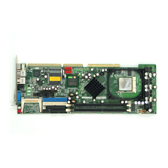
ROCKY-4786EVG CPU Card ROCKY-4786EVG CPU Board Overview Figure 1-1 ROCKY-4786EVG CPU Board Overview 1.2.1 ROCKY-4786EVG CPU Board Connectors The ROCKY-4786EVG CPU board has the following connectors onboard: 1 x ATX 12V connector 1 x CPU cooling fan connector 1 x IrDA connector... -
Page 16: Technical Specifications
The ROCKY-4786EVG CPU board has the following connectors on the board rear panel: 1 x PS/2 connector 1 x VGA connector 1 x LINE_OUT connector 1 x RJ-45 Ethernet connector 2 x USB ports The location of these connectors on the CPU Card can be seen in Error! Reference source not found.. -
Page 17: Table-1-1: Technical Specifications
ROCKY-4786EVG CPU Card devices Floppy Disk Drive (FDD) Supports FDD USB Interfaces Eight USB 2.0 connectors supported Serial Ports Two COM ports Real Time Clock 256-byte battery backed CMOS RAM Hardware Monitoring Cooling fans, temperature and system voltages Power Management Supports Advanced Configuration and Power Interface (ACPI) Specifications Revision 2.0... - Page 18 THIS PAGE IS INTENTIONALLY LEFT BLANK ® Technology, Corp. 1-18...
-
Page 19: Detailed Specifications
ROCKY-4786EVG CPU Card Chapter Detailed Specifications 1-19... -
Page 20: Compatible Iei Backplanes
Compatible IEI Backplanes The ROCKY-4786EVG CPU card is compatible with all IEI PICMG1.0 backplanes. For more information on these backplanes, please visit the IEI website or contact your CPU card reseller or vendor. CPU Support Table-2-1 lists the CPUs supported by the ROCKY-4786EVG CPU board. -
Page 21: Onboard Chipsets
ROCKY-4786EVG CPU Card Onboard Chipsets 2.3.1 Northbridge and Southbridge Chipsets The following chipsets are preinstalled on the board: ® Northbridge: Intel 865GV ® Southbridge: Intel ICH5 The following two sections (Section 2.3.2 and Section 2.3.3) list some of the features of the 865GV and the ICH5 chipsets. -
Page 22: Data Flow
AC-Link for Audio and Telephony Codecs Interrupt Controller High-Precision Event Timers 1.5 V operation with 3.3 V I/O Timers Based on 82C54 Integrated 1.5 V Voltage Regulator (INTVR) for the Suspend wells Power Management Logic External Glue Integration Flash BIOS I/F supports BIOS Memory size up to 8 Mbytes Low Pin Count (LPC) I/F Enhanced DMA Controller Real-Time Clock... -
Page 23: Figure-2-1: Data Flow Block Diagram
ROCKY-4786EVG CPU Card Figure-2-1: Data Flow Block Diagram 1-23... -
Page 24: Graphics Support
Graphics Support The graphics features listed below are all integrated on the 865GV northbridge chipset. Enhanced Rapid Pixel and Texel Rendering Zone Rendering 2 Technology Dynamic Video Memory Technology v2.0 Enhanced Intelligent Memory Management Enhanced 2D 256-bit internal path 8/16/32bpp DirectDraw*, GDI, GDI+ Anti-aliased text support Alpha blending... -
Page 25: Memory Support
Multiple display types (LVDS, DVI, TV-out, CRT) Memory Support The ROCKY-4786EVG CPU has two 184-pin dual inline memory module (DIMM) sockets and supports up to two un-buffered DDR DIMMs with the following specifications: Maximum RAM: 2GB (1GB module in each slot) - Page 26 PCI power management registers by MCH MAC Specific Optimized transmit and receive queues IEEE 802.3x-compliant flow-control support with software-controllable thresholds Caches up to 64 packet descriptors in a single burst Programmable host memory receive buffers (256 B to 16 KB) and cache line size (16 B to 256 B) Wide, optimized internal data path architecture 40 KB configurable Transmit and Receive FIFO buffers...
-
Page 27: Drive Interfaces
Supports an Ultra ATA/100/66/33 DMA protocol with data transfer rates up to 100MB/s 2.9.3 Floppy Disk Drive (FDD) The ROCKY-4786EVG CPU Board supports a single FDD. The following FDD formats are compatible with the board. 5.25”: 360KB and 1.2MB 3.5”: 720KB, 1.44MB and 2.88MB 2.10 Serial Ports... -
Page 28: Real Time Clock
2.14 USB Interfaces The ROCKY-4786EVG CPU board has eight internal USB interfaces. The USB interfaces support USB 2.0. 2.15 BIOS The ROCKY-4786EVG CPU Board uses a licensed copy of Award BIOS. Flash BIOS features used are listed below: ® Technology, Corp. -
Page 29: Operating Temperature And Temperature Control
Console redirection function support PXE (Pre-Boot Execution Environment ) support USB booting support 2.16 Operating Temperature and Temperature Control The maximum and minimum operating temperatures for the ROCKY-4786EVG CPU Board are listed below. Minimum Operating Temperature: 0ºC (32°F) Maximum Operating Temperature: 60°C (140°F) A cooling fan and heat sink must be installed on the CPU. -
Page 30: Power Consumption
Standard 48-pin LQFP package 2.18 Power Consumption Table 2-2 shows the power consumption parameters for the ROCKY-4786EVG CPU board when a Pentium 4 processor with a clock speed of 3.0GHz, an L2 cache of 2MB and a FSB 800MHz is running with a 2GB DDR400 module. -
Page 31: Packaged Contents And Optional Accessory Items
7.52 Table 2-2: Power Consumption 2.19 Packaged Contents and Optional Accessory Items 2.19.1 Package Contents When you unpack the ROCKY-4786EVG CPU board, you should find the following components. 1 x ROCKY-4786EVG CPU card. 1 x SATA power cable (P/N: 32100-088600-RS). - Page 32 THIS PAGE IS INTENTIONALLY LEFT BLANK ® Technology, Corp. 1-32...
-
Page 33: Connectors And Jumpers
ROCKY-4786EVG CPU Card Chapter Connectors and Jumpers 1-33... -
Page 34: Peripheral Interface Connectors
The locations of the peripheral interface connectors are shown in Section 3.1.1. A complete list of all the peripheral interface connectors can be seen in Section 3.1.2. 3.1.1 ROCKY-4786EVG CPU Board Layout Figure 3-1 shows the onboard peripheral connectors, backplane peripheral connectors and onboard jumpers. -
Page 35: Peripheral Interface Connectors
ROCKY-4786EVG CPU Card 3.1.2 Peripheral Interface Connectors Table 3-1 shows a list of the peripheral interface connectors on the ROCKY-4786EVG CPU board. Detailed descriptions of these connectors can be found in Section 3.2. Label Connector Type IDE1 Primary & Secondary IDE connectors... -
Page 36: Rear Panel Connectors
Backplane to Main board ATX power 3-pin header control Connector Table 3-1: Peripheral Interface Connectors 3.1.3 Rear Panel Connectors Table 3-2 lists the rear panel connectors on the ROCKY-4786EVG CPU card. Detailed descriptions of these connectors can be found in Section 4.5. Label Connector Type... -
Page 37: Internal Peripheral Connectors
CN Type: 2x17 pin header CN Location: See Figure 3-2 CN Pinouts: See Table 3-4 The ROCKY-4786EVG is shipped with a 34-pin daisy-chain drive connector cable. This cable can be connected to the FDD connector. DESCRIPTION DESCRIPTION REDUCE WRITE INDEX#... -
Page 38: Figure 3-2: Fdd Connector Location
WRITE GATE# TRACK 0# WRITE PROTECT# READ DATA# HEAD# DISK CHANGE# Table 3-4: FDD Connector Pinouts Figure 3-2: FDD Connector Location ® Technology, Corp. 1-38... -
Page 39: Ide Connectors
ROCKY-4786EVG CPU Card 3.2.2 IDE Connectors CN Label: IDE1 (primary) and IDE2 (secondary) CN Type: 2x20 pin header CN Location: See Figure 3-3 CN Pinouts: See Table 3-5: IDE Connector Pinouts Two IDE connectors provide connectivity for four IDE devices. -
Page 40: Figure 3-3: Ide Connector Locations
Figure 3-3: IDE Connector Locations ® Technology, Corp. 1-40... -
Page 41: Com Ports
COM1, COM2 CN Type: 2x5 pin headers CN Location: CN Pinouts: See Table-3-6 The ROCKY-4786EVG offers two high speed NS16C550 compatible UART’s with 16-byte Read/Receive FIFO serial ports. DESCRIPTION DESCRIPTION DATA CARRIER DETECT (DCD) DATA SET READY (DSR) RECEIVE DATA (RXD) -
Page 42: Figure 3-4 Com Port Locations
Figure 3-4 COM Port Locations ® Technology, Corp. 1-42... -
Page 43: Parallel Port
ROCKY-4786EVG CPU Card 3.2.4 Parallel Port CN Label: LPT1 CN Type: 2x13 pin header CN Location: See Figure-3-5 CN Pinouts: See Table-3-7 The parallel port is connected to a printer or other parallel device with a 26-pin flat-cable connector. DESCRIPTION... -
Page 44: Figure-3-5: Lpt Connector Location
Figure-3-5: LPT Connector Location ® Technology, Corp. 1-44... -
Page 45: Internal Usb Connectors
ROCKY-4786EVG CPU Card 3.2.5 Internal USB Connectors CN Label: USB1, USB2, USB3, USB4 CN Type: 2x4 pin header CN Location: See Figure-3-6 CN Pinouts: See Table-3-8 Four 2x4 pin connectors provide connectivity to eight USB 2.0 ports. The USB ports are used for I/O bus expansion. -
Page 46: Figure-3-6: Usb Port Connector Location
Figure-3-6: USB Port Connector Location ® Technology, Corp. 1-46... -
Page 47: Cooling Fan Connector
ROCKY-4786EVG CPU Card 3.2.6 Cooling Fan Connector CN Label: FAN1, FAN2 CN Type: 1x3 pin header CN Location: See Figure 3-7 CN Pinouts: See Table 3-9 The FAN1 and FAN2 cooling fan connectors provide a 12V, 350mA ~ 740mA or 1A ~ 2.2A current to the cooling fans. -
Page 48: Backplane To Mainboard Atx Connector
Figure 3-7 Cooling Fan Connector Locations 3.2.7 Backplane to Mainboard ATX Connector CN Label: ATXCTL1 CN Type: 1x3 pin header CN Location: See Figure 3-8 ® Technology, Corp. 1-48... -
Page 49: Figure 3-8: Atxctl Connector Locations
ROCKY-4786EVG CPU Card CN Pinouts: See Table 3-10 Connects a power source from a backplane with an ATX Connector. PIN NO. DESCRIPTION 5VSB ATX-ON Table 3-10: CN7 Connector Pin Outs Figure 3-8: ATXCTL Connector Locations 1-49... -
Page 50: System Front Panel Connector
3.2.8 System Front Panel Connector CN Label: CN Type: 2x7 pin header CN Location: See Figure 3-9 CN Pinouts: See Table 3-10 The system panel connector connects to: the system chassis front panel LEDs the chassis speaker the power switch the reset button. -
Page 51: Irda Connector
ROCKY-4786EVG CPU Card Figure 3-9: System Panel Connector Location 3.2.9 IrDA Connector CN Label: CN Type: 1x6 pin header CN Location: See Figure 3-10 CN Pinouts: See Table 3-12 1-51... -
Page 52: Figure 3-10: Irda Connector Location
The integrated IrDA connector supports both the SIR and ASKIR infrared protocols. DESCRIPTION IR-RX IR-TX CIRRX Table 3-12: IrDA Connector Pinouts Figure 3-10: IrDA Connector Location ® Technology, Corp. 1-52... -
Page 53: Sata Drive Connectors
ROCKY-4786EVG CPU Card 3.2.10 SATA Drive Connectors CN Label: SATA1, SATA2 CN Type: 1x7 pin port CN Location: See Figure 3-11 CN Pinouts: See Table 3-13 The SATA drive ports provide connectivity to SATA drives with a maximum data transfer rate of 150MB/s. -
Page 54: Figure 3-11: Sata Connector Locations
Figure 3-11: SATA Connector Locations ® Technology, Corp. 1-54... -
Page 55: Keyboard Connector
ROCKY-4786EVG CPU Card NOTE: 1. SATA is supported by: • Windows 2000 SP4 • Windows XP SP1 • Windows 2003, or later versions. 2. Older OSes, such as Windows 98SE or ME, do not support the SATA interface. 3.2.11 Keyboard Connector... -
Page 56: Figure 3-12: Cn5 Connector Location
Figure 3-12: CN5 Connector Location ® Technology, Corp. 1-56... -
Page 57: Atx-12V Power Source Connector
ROCKY-4786EVG CPU Card 3.2.12 ATX-12V Power Source Connector CN Label: CN Type: 2x2 pin header CN Location: See Figure 3-13 CN Pinouts: See Table 3-15 This connector supports the ATX-12V power supply. PIN NO. DESCRIPTION PIN NO. DESCRIPTION +12V +12V... -
Page 58: External (Rear Panel) Connectors
External (Rear Panel) Connectors Figure 3-14 shows the ROCKY-4786EVG CPU board rear panel. The peripheral connectors on the back panel can be connected to devices externally when the CPU card is installed in a chassis. The peripheral connectors on the rear panel are:... -
Page 59: Ethernet Connectors
ROCKY-4786EVG CPU Card The PS/2 mouse and keyboard connectors are connected to a mouse and keyboard DESCRIPTION DESCRIPTION KB Data Clock Table 3-16: PS/2 Pinouts Figure 3-15: PS/2 Pinout locations 3.3.2 Ethernet Connectors CN Label: LAN1, LAN2 CN Type: RJ-45... -
Page 60: Line Out Connector
DESCRIPTION DESCRIPTION TXD+ TXD- GRN+ RXD+ GRN- CT_TXD YEL- CT_RXD YEL+ RXD- S GND S GND Table 3-17: RJ-45 Ethernet Connector Pinouts Figure 3-16: RJ-45 Ethernet Connector The RJ-45 Ethernet connector has two status LEDs, one green and one yellow. The green LED indicates activity on the port and the yellow LED indicates the port is linked. -
Page 61: Vga Connector
ROCKY-4786EVG CPU Card 3.3.4 VGA Connector CN Label: VGA1 CN Type: See Figure 3-17 CN Location: See Figure 3-14 (labeled number 4) The standard 15-pin VGA connector connects to a CRT or LCD display monitor. DESCRIPTION DESCRIPTION No Connect Green... -
Page 62: Jumpers
OPEN a jumper means removing the plastic clip from a Figure 3-18 Jumper jumper. The ROCKY-4786EVG CPU Board has two onboard jumpers. See Table 3-3. ® Technology, Corp. 1-62... -
Page 63: Figure 3-19: Jumper Locations
ROCKY-4786EVG CPU Card Figure 3-19: Jumper Locations 1-63... -
Page 64: Reset Cmos Jumper
3.4.1 Reset CMOS Jumper Jumper Label: Jumper Type: 3 pin header Jumper Settings: See Table 3-20 Jumper Location: See Figure 3-19 If the CPU Card fails to boot due to improper BIOS setting, use this jumper to clear the CMOS data and reset the system BIOS information. To do this, use the jumper cap to close pins 2 and 3 for a few seconds then reinstall the jumper clip back to pins 1 and 2. -
Page 65: Installation And Configuration
ROCKY-4786EVG CPU Card Chapter Installation and Configuration 1-65... -
Page 66: Installation Considerations
Failing to adhere to these precautions may lead to severe damage of the CPU card and injury to the person installing the CPU card. 4.1.1 Installation Notices Before and during the installation of the ROCKY-4786EVG CPU Board, please DO the following: Read the user manual... -
Page 67: Unpacking
CPU card from. 4.2.1 Unpacking Precautions Before you install the ROCKY-4786EVG CPU card, you must unpack the CPU card. Some components on ROCKY-4786EVG are very sensitive to static electricity and can be damaged by a sudden rush of power. -
Page 68: Checklist
1 x QIG (quick installation guide) If one or more of these items are missing, please contact the reseller or vendor you purchased the ROCKY-4786EVG CPU card from and do not proceed any further with the installation. ROCKY-4786EVG CPU Card Installation WARNING! 1. -
Page 69: Cpu Installation
ROCKY-4786EVG CPU Card WARNING! When installing electronic components onto the CPU Card always take the following anti-static precautions in order to prevent ESD damage to your board and other electronic components like the CPU and DIMM modules The following components must be installed onto the CPU Card or connected to the CPU Card during the installation process. -
Page 70: Cooling Kit Cf-519 Installation
Correctly orientate the CPU with the IHS (Integrated Heat Sink) side facing Step 4: upward. Locate the pin 1 mark on the CPU. Step 5: Gently insert the CPU into the socket. Step 6: Lower the lever into the locked position.Step 0: Step 7: Figure 4-1: Locking the CPU into the CPU Socket... -
Page 71: Dimm Module Installation
ROCKY-4786EVG CPU Card the CPU card. Align the bracket with the four retention holes at the back of the CPU card. Once properly aligned, insert four retention screws from the front of the CPU card. Figure 4-2: Cooling Kit Support Bracket Open the lever at the top of the heat sink. -
Page 72: Dimm Module Installation
Both DIMMs must be either single-sided or dual-sided. 4.3.3.2 DIMM Module Installation The ROCKY-4786EVG CPU Board has two DDR SDRAM DIMM sockets. To install the DIMM modules, follow the instructions below. Pull the two white handles on either side of the DIMM socket down. -
Page 73: Ide Disk Drive Connector (Ide1)
ROCKY-4786EVG CPU Card 4.3.4.1 IDE Disk Drive Connector (IDE1) The cable used to connect the CPU card to the IDE HDD is a standard 44-pin ATA 66/100 flat cable. To connect an IDE HDD to the CPU Card, follow the instructions below. -
Page 74: Chassis Installation
Chassis Installation After the CPU, the cooling kit, and the DIMM modules have been installed and after the internal peripheral connectors have been connected to the peripheral devices and the jumpers have been configure, the CPU Card can be mounted into chassis. To mount the CPU Card into a chassis please refer to the chassis user guide that came with the product. -
Page 75: Award Bios Setup
ROCKY-4786EVG CPU Card Chapter Award BIOS Setup 1-75... -
Page 76: Introduction
Introduction A licensed copy of Phoenix Award BIOS is preprogrammed into the ROM BIOS. The BIOS setup program allows users to modify the basic system configuration. This chapter describes how to access the BIOS setup program and the configuration options you may change. -
Page 77: Getting Help
ROCKY-4786EVG CPU Card General help, only for Status Page Setup Menu and Option Page Setup Menu Item help Previous values for the page menu items Fail-safe defaults for the current page menu items Optimized defaults for the current page menu items... -
Page 78: Main Bios Menu
5.1.5 Main BIOS Menu Once the BIOS opens, the main menu (BIOS Menu 1) appears. BIOS Menu 1: Award BIOS CMOS Setup Utility NOTE: The following sections will completely describe the menus listed below and the configuration options available to users. The following menu options are seen in BIOS Menu 1. -
Page 79: Load Fail-Safe Defaults
ROCKY-4786EVG CPU Card Frequency/Voltage Control: Configures the CPU Clock Ratio, Auto Detect DIMM/PCI CLk and Spread Spectrum settings The following user configurable options are also available in the BIOS Main Menu Load Fail-Safe Defaults This option allows you to load failsafe default values for each of the parameters on the Setup menus. -
Page 80: Standard Cmos Features
Exit Without Saving If you have finished making configuration changes but do not want to save them and you want to exit the BIOS menus, select this option. Standard CMOS Features The Standard CMOS Features menu (BIOS Menu 2) changes basic BIOS configuration options. -
Page 81: Drive A [1.44M, 3.5In]
ROCKY-4786EVG CPU Card Primary IDE Slave Secondary IDE Master Secondary IDE Slave The IDE Configuration menu (BIOS Menu 3) allows you to set or change the configurations for the IDE devices installed in the system. If an IDE device is detected, and one of the above listed four BIOS configuration options are selected, the IDE configuration options shown in Section 5.2.1 appear. - Page 82 EGA/VGA Selected when the adapter for the primary system EFAULT monitor is one of the following: SEGA SVGA CGA 40 The system will power up in 40 column mode CGA 80 The system will power up in 80 column mode MONO A monochrome monitor is used.
-
Page 83: Ide Channel Master
ROCKY-4786EVG CPU Card or a disk error; it will stop for all other errors. Base Memory: The Base Memory is NOT user configurable. The POST will determine the amount of base (or conventional) memory installed in the system. The value of the base memory is typically 512K for systems with 512K memory installed on the CPU card or 640K for systems with 640K or more memory installed on the motherboard. -
Page 84: Ide Hdd Auto-Detection [Press Enter]
BIOS Menu 3: IDE Channel Master IDE HDD Auto-Detection [Press Enter] Selecting IDE HDD Auto-Detection option and pressing the “E ” key will enable the NTER BIOS to automatically detect the HDD type. Do not set this option manually. IDE Channel 0/1 Master/Slave [Auto] The IDE Channel option allows you to activate or deactivate the following drive channels: Channel 0 Master Channel 0 Slave... -
Page 85: Access Mode [Auto]
ROCKY-4786EVG CPU Card Manual Selecting this option allows you to manually configure the device on the IDE channel in BIOS. Access Mode [Auto] The Access Mode option allows you to determine the hard disk BIOS translation modes. Most systems now use hard drives with large capacities and therefore either the LBA translation mode or auto mode should be selected. -
Page 86: Advanced Bios Features
Precomp The Precomp specification indicates on which track the write precompensation begins. Landing Zone The Landing Zone specification tells the user where the disk head will park itself after the system powers off. Sector The Sector specification tells the user how many logical sectors the HDD has been divided into. -
Page 87: Virus Warning [Disabled]
ROCKY-4786EVG CPU Card Hard Disk Boot Priority To access these menus, use the arrow keys to select the menu option and press the “E ” button. The menu will appear. The menus are discussed fully in Section 5.3.1: NTER CPU Feature and Section 5.3.2: Hard Disk Boot Priority below. -
Page 88: Quick Power On Self Test [Enabled]
Enabled The L1 and L2 CPU caches are both turned on EFAULT Disabled The L1 and L2 CPU caches are both turned off Quick Power On Self Test [Enabled] The Quick Power On Self Test configuration option speeds up the POST after you turn on the computer. -
Page 89: Boot Other Device [Enabled]
ROCKY-4786EVG CPU Card Boot Other Device [Enabled] The Boot Other Device option determines whether the CPU card will use a second or third boot device if the first boot device is not found. Enabled The system will look for second and third boot devices if EFAULT the first one is not found. -
Page 90: Boot Up Numlock Status [On]
Boot Up Numlock Status [On] The Boot Up Numlock Status option allows you to determine the default state of the numeric keypad. The keys on the keypad will be arrow keys The keys on the keypad will be number keys EFAULT Gate A20 Option [Fast] The Gate A20 Option option refers to the way the system addresses memory above 1 MB... -
Page 91: Typematic Delay (Msec) [250]
ROCKY-4786EVG CPU Card 6 characters per second EFAULT 8 characters per second 10 characters per second 12 characters per second 15 characters per second 20 characters per second 24 characters per second 30 characters per second x Typematic Delay (Msec) [250] The Typematic Delay can only be configured if the Typematic Rate Setting is enabled. -
Page 92: Apic Mode [Enabled]
the correct password is not entered at the prompt. NOTE: To disable security, select the password setting in the Main Menu. When asked to enter a password, do not type anything, press, “E ” and the NTER security is disabled. Once the security is disabled, the system will boot and you can enter Setup freely. -
Page 93: Cpu Feature
ROCKY-4786EVG CPU Card Only select this if you are using the OS/2 operating system If you are not using the OS/2 operating system then Non-OS2 EFAULT disable this function. Small Logo (EPA) Show [Disabled] The Small Logo (EPA) Show option determines if the Environmental Protection Agency (EPA) logo will appear during the system boot-up process. - Page 94 The Thermal Management configuration option allows you to select the thermal monitor the CPU will use to monitor its own operating temperature. Once the thermal monitor detects that the CPU is reaching its maximum operating temperature, the thermal monitor will automatically throttle the CPU (reduce the number of CPU processing cycles) in order to cool the CPU down to a safe operating temperature.
-
Page 95: Hard Disk Boot Priority
ROCKY-4786EVG CPU Card 5.3.2 Hard Disk Boot Priority The Hard Disk Boot Priority menu (BIOS Menu 6) is shown below. BIOS Menu 6: Hard Disk Boot Priority 1-95... -
Page 96: Advanced Chipset Features
Advanced Chipset Features The Advanced Chipset Features menu (BIOS Menu 7) allows you to change the configuration for the chipset configuration options. BIOS Menu 7: Advanced Chipset Features DRAM Timing Selectable [Manual] The DRAM Timing Selectable configuration option allows you to select whether the manufacturer recommended settings for the following DRAM configuration options are automatically detected by the BIOS or if you manually select the DRAM settings. -
Page 97: Cas Latency Time [2]
ROCKY-4786EVG CPU Card Manual You set the above configuration options manually EFAULT By SPD The BIOS automatically detects the settings recommended by the manufacturer CAS Latency Time [2] The CAS Latency Time configuration option refers to the Column Address Strobe (CAS) delay time. -
Page 98: Dram Ras# Precharge [3 Clocks]
2 nanoseconds DRAM RAS# Precharge [3 clocks] The DRAM RAS# Precharge option indicates how fast your RAM can terminate the access of one row and start accessing another. (To be able to change this configuration option the DRAM RAS# Precharge configuration option must be set to “Manual”) The following configuration options are available 4 clocks 3 clocks (D... -
Page 99: Memory Hole At 15M - 16M [Disabled]
ROCKY-4786EVG CPU Card Enabled Video BIOS is cached in the L2 cache Memory Hole At 15M – 16M [Disabled] The Memory Hole At 15M – 16M reserves the memory space between 15MB and 16MB for ISA expansion cards that require a specified area of memory to work properly. If you are using older ISA expansion cards, please refer to the documentation that came with the card to see if it is necessary to reserve the space. -
Page 100: Init Display First [Pci Slot]
Init Display First [PCI Slot] The Init Display First option selects whether to boot from the PCI slot or the onboard AGP. PCI Slot The system will boot from the PCI graphics card. EFAULT The system will boot from the AGP graphics card Onboard/AGP On-Chip VGA [Enabled] The On-Chip VGA option is found on motherboards that have a built-in graphics processor... -
Page 101: Integrated Peripherals
ROCKY-4786EVG CPU Card Boot Display [Auto] The Boot Display option allows you to select the display device the system will boot with. Auto The system will automatically determine the display EFAULT device type. The display device type will be set as CRT... -
Page 102: Onchip Ide Device
The optimal number of block read/writes per sector the EFAULT drive can support will be automatically detected. On-Chip Primary PCI IDE [Enabled] The On-Chip Primary PCI IDE option allows you to determine whether or not the ROCKY-4786EVG will use the integrated primary IDE channel. 1-10 ® Technology, Corp. -
Page 103: Ide Pio [Auto]
ROCKY-4786EVG CPU Card Disabled The CPU card will not use the primary IDE channel Enabled The CPU card will use the primary IDE channel EFAULT IDE PIO [Auto] The Programmed Input/Output (PIO) mode for the following HDDs can all be selected. -
Page 104: On Chip Serial Ata [Disabled]
The On-Chip Secondary PCI IDE option allows you to determine if the motherboard should or should not use the integrated primary IDE channel. Disable this if you use an IDE adapter card for your IDE hard drives. Disabled The CPU card will not use the integrated primary IDE channel Enabled The CPU card will use the integrated primary IDE... -
Page 105: Onboard Device
ROCKY-4786EVG CPU Card 5.5.2 Onboard Device The Onboard Device menu (BIOS Menu 10) allows you to change the USB, Audio and LAN device configurations. BIOS Menu 10: OnBoard Device [Integrated Peripherals] USB Controller [Enabled] The USB Controller option allows you to activate or deactivate the onboard USB controller. -
Page 106: Superio Device
USB Keyboard Support [Disabled] The USB Keyboard Support is only applicable if you are using a USB keyboard. Some OSes do not support USB keyboards. Enabling this option in BIOS will allow users using an OS that does not support USB keyboard to implement a USB keyboard. USB keyboard support no provided by BIOS Disabled EFAULT... -
Page 107: Power On Function [Button Only]
ROCKY-4786EVG CPU Card BIOS Menu 11: SuperIO Device [Integrated Peripherals] POWER ON Function [BUTTON ONLY] The POWER ON Function option allows you to select the method you use to turn on the system. When you turn on the computer you will be... -
Page 108: Kb Power On Password [Enter]
Keyboard 98 If you are using Windows 98 or better and have the appropriate keyboard, you can use the keyboard's wake-up or power-on button to start up the computer. x KB Power ON Password [Enter] The KB Power ON Password option can only be specified if you have selected the Password as the POWER ON Function option. -
Page 109: Onboard Serial Port 1 [3F8/Irq4]
ROCKY-4786EVG CPU Card Disabled Disable this option if you use an adapter for your FDDs EFAULT or if you have no FDDs connected Select this option if FDDs are connected to the board Enabled and will use the onboard FDD controller. -
Page 110: Rxd, Txd Active [Hi,Lo]
selected, COM2 will be disabled. ASKIR ASKIR is set as the IR serial mode. If this option is selected, COM2 will be disabled. Normal COM2 is enabled and the IR device disabled EFAULT x RxD, TxD Active [Hi,Lo] The RxD, TxD Active BIOS option allows you to set the infra-red reception (RxD) and transmission (TxD) polarity. -
Page 111: Parallel Port Mode [Spp]
ROCKY-4786EVG CPU Card Disabled 378/IRQ7 (D EFAULT 278/IRQ5 3BC/IRQ7 Parallel Port Mode [SPP] The Parallel Port Mode selection allows you to select the mode the parallel port will operate in. The parallel port will operate in the standard parallel port EFAULT (SPP) mode. -
Page 112: Power Management Setup
parallel port will operate in. Please refer to the parallel device that your system will be connected to and select the EPP mode accordingly. EPP1.9 EPP 1.9 is selected as the EPP standard EPP1.7 EPP 1.7 is selected as the EPP standard EFAULT x ECP Mode Use DMA [3] If the ECP mode is selected in the Parallel Port Mode configuration option, you will be... -
Page 113: Power-Supply Type [At]
ROCKY-4786EVG CPU Card BIOS Menu 12: Power Management Setup Power-Supply Type [AT] The following configuration options are available, AT (D EFAULT ACPI Function [Enabled] The ACPI Function option allows you to enable or disable the ACPI function. The ACPI function is enabled... -
Page 114: Run Vgabios If S3 Resume [Auto]
S3(STR) System appears off. The CPU has no power; RAM is in slow refresh; the power supply is in a reduced power mode. S1&S3 The BIOS will be able to support both the S1 and the S3 suspend states described above. x Run VGABIOS if S3 Resume [Auto] If the S3(STR) or S1&S3 option is selected in ACPI Suspend Type above, you will be able to configure the Run VGABIOS if S3 Resume option. -
Page 115: Video Off Method [Dpms]
ROCKY-4786EVG CPU Card power saving. Max. Saving BIOS automatically sets the Suspend Mode time and the HDD Power Down time for maximum power saving. The minimum and maximum power settings are shown below: Suspend Mode HDD Power Down Min. Saving... -
Page 116: Suspend Type [Stop Grant]
The display monitor will be turned off when the system is in EFAULT suspend mode. Suspend Type [Stop Grant] The Suspend Type option allows you to determine what suspend state the CPU will go into when the system is in the suspend state. Stop Grant When the CPU is in the stop grant state the bus clock EFAULT... -
Page 117: Hdd Power Down [Disabled]
ROCKY-4786EVG CPU Card Management option, you will not be able to configure this setting. The following settings can be made. Disable (Default) 1 Min 2 Min 3 Min 4 Min 8 Min 12 Min 20 Min 30 Min 40 Min... -
Page 118: Soft -Off By Pwr-Bttn [Instant-Off]
14 Min 15 Min Soft –Off by PWR-BTTN [Instant-Off] The Soft –Off by PWR-BTTN option allows you to define how the system responds when the power button is pushed. You may choose to allow the system to be either turned off completely or enter into a suspend mode. -
Page 119: Usb Kb Wake-Up From S3 [Disabled]
ROCKY-4786EVG CPU Card Enabled The system will be woken from a suspend state EFAULT when the modem rings x USB KB Wake-Up From S3 [Disabled] If you selected either the S3(STR) or the S1&S3 option in the ACPI Suspend Type option, you will be able to configure the USB KB Wake-Up From S3. -
Page 120: Pnp/Pci Configurations
The Time (hh:mm:ss) Alarm option can only be configured if the Resume by Alarm option has been enabled. You will have to set the time you wish the computer to be roused. You will see three zeroes side by side. The first zero is for the hour, the second zero for the minutes and the third zero for the seconds. -
Page 121: Pnp Os Installed [No]
ROCKY-4786EVG CPU Card BIOS Menu 13: PnP/PCI Configurations PNP OS Installed [No] The PNP OS Installed option allows you to determine whether the Plug and Play devices connected to your system will be configured by the operating system or the BIOS. -
Page 122: Resources Controlled By [Auto (Escd)]
Enabled ESCD will be reconfigured after you exit setup Resources Controlled By [Auto (ESCD)] The Resources Controlled By option gives you the option of manually configuring all the boot and plug and play devices, or allowing BIOS to configure these devices automatically. If you allow BIOS to configure it automatically you will not be able to select the IRQs, DMA and memory base address fields because BIOS will automatically assign them. - Page 123 ROCKY-4786EVG CPU Card BIOS Menu 14: IRQ Resources The menu will have the following 12 BIOS configuration options: IRQ-3 assigned to IRQ-4 assigned to IRQ-5 assigned to IRQ-6 assigned to IRQ-7 assigned to IRQ-8 assigned to IRQ-9 assigned to IRQ-10 assigned to...
-
Page 124: Dma Resources [Press Enter]
compliant with the original PC AT bus specification, PCI/ISA PNP for devices compliant with the Plug and Play standard whether designed for PCI or ISA bus architecture. Reserved The IRQ is reserved by BIOS x DMA Resources [Press Enter] If you select manual in the Resources Controlled By option then you will be able to configure the DMA Resources. -
Page 125: Pc Health Status
ROCKY-4786EVG CPU Card in use. This option is only very rarely needed. It should be left at "Disabled" unless a video device specifically requires the setting enabled upon installation. Disabled Does not allow the graphics devices to examine the VGA... -
Page 126: Frequency/Voltage Control
System Temperature CPU Temperature Voltages The following voltages are monitored CPU Vcore +1.5 V +3.3 V +5 V +12 V -12 V Fan Speeds The following fan speeds are monitored: CPU an Speed System Fan Speed Frequency/Voltage Control The Frequency/Voltage Control menu (BIOS Menu 16) allows you to configure the Auto Detect DIMM/PCI CLk and Spread Spectrum settings. -
Page 127: Auto Detect Dimm/Pci Clk [Enabled]
ROCKY-4786EVG CPU Card BIOS Menu 16: Frequency/Voltage Control The following system parameters are controlled by the Frequency/Voltage Control menu (BIOS Menu 16). Auto Detect DIMM/PCI CLk [Enabled] The Auto Detect DIMM/PCI CLk option allows BIOS to monitor power consumption to the AGP, PCI and SDRAM DIMM slots and reduce EMI (Electromagnetic Interference) by turning them off when unoccupied or inactive. - Page 128 (Electromagnetic Interference) Disabled Does not monitor system clocking EFAULT 1-12 ® Technology, Corp.
-
Page 129: Software Drivers
ROCKY-4786EVG CPU Card Chapter Software Drivers 1-12... -
Page 130: Available Software Drivers
All five drivers can be found on the CD that came with the CPU card. To install the drivers please follow these instructions: Insert the CD into the system that contains the ROCKY-4786EVG CPU card. From the IEI Driver CD main menu, click the Rocky Series menu item to go to the Rocky Series menu. -
Page 131: Chipset Driver Installation
ROCKY-4786EVG CPU Card Figure 6-1: IEI Driver CD Rocky-4786EVG/Rocky-4786E2V Menu NOTE: If your system does not run the "autorun" program when the CD is inserted, click the start button, select run, then type D:\autorun.exe (replace D with the actual drive letter for your CD-ROM) to access the IEI Driver CD main menu. -
Page 132: Figure 6-2: Chipset Software Installation Utility Welcome Screen
Once you click the Win98\ME\2000\XP icon, a welcome screen shown in Figure Step 4: 6-2 appears. Figure 6-2: Chipset Software Installation Utility Welcome Screen After the welcome screen shown in Figure 6-2 appears, to continue the Step 5: installation process click the “N ”... -
Page 133: Figure 6-3: Chipset Software Installation Utility License Agreement
ROCKY-4786EVG CPU Card Figure 6-3: Chipset Software Installation Utility License Agreement Read the license agreement in Figure 6-3. If you choose to accept the terms Step 6: and conditions stipulated in the agreement, click the “Y ” button. The Readme file information shown in Figure 6-4 will appear. -
Page 134: Figure 6-4: Chipset Software Installation Utility Readme File Information
Figure 6-4: Chipset Software Installation Utility Readme File Information After reading through the Readme file information shown in Figure 6-4 click on Step 7: the “N ” button and the chipset driver will be installed. After the driver installation process is complete, a confirmation screen shown in Step 8: Figure 6-5 will appear. -
Page 135: Intel Graphics Media Accelerator Driver
ROCKY-4786EVG CPU Card Figure 6-5: Chipset Software Installation Utility Complete The confirmation screen shown in Figure 6-5 allows you to restart the computer Step 9: immediately after the installation is complete or to restart the computer later. For the settings to take effect, the computer must be restarted. Once you have decided when to restart the computer, click the “F... -
Page 136: Figure 6-6: Gma Driver Installation Welcome Screen
Figure 6-6: GMA Driver Installation Welcome Screen To continue installing click “Next” and a license agreement shown in Figure 6-7 Step 3: will appear. Read the license agreement. 1-13 ® Technology, Corp. -
Page 137: Figure 6-7: Gma Driver License Agreement
ROCKY-4786EVG CPU Card Figure 6-7: GMA Driver License Agreement If you choose to accept the terms and conditions stipulated in the license Step 4: agreement shown Figure 6-7, click the “Y ” button. The installation notice shown in Figure 6-8 will appear. -
Page 138: Lan Driver Installation
Figure 6-9: GMA Driver Installation Complete The confirmation screen shown in Figure 6-9 allows you to restart the computer Step 6: immediately after the installation is complete or to restart the computer later. For the settings to take effect, the computer must be restarted. Once you have decided when to restart the computer, click the “F ”... -
Page 139: Figure 6-10: Lan Driver License Agreement
ROCKY-4786EVG CPU Card Figure 6-10: LAN Driver License Agreement If you choose to accept the terms and conditions stipulated in the license Step 3: agreement shown Figure 6-10, click the “N ” button. The location to save files shown in Figure 6-11 will appear. -
Page 140: Figure 6-11: Lan Location To Save Files
Figure 6-11: LAN Location to Save Files Select the folder to save the file in and click the “Next” button. The installation Step 4: notice shown in Figure 6-12 will appear, after which the Intel® PRO Network Connections menu shown Figure 6-13 will immediately appear. 1-14 ®... -
Page 141: Figure 6-12: Lan Extracting Files Notice
ROCKY-4786EVG CPU Card Figure 6-12: LAN Extracting Files Notice 1-14... -
Page 142: Figure 6-13: Intel® Pro Network Connections Main Menu
Figure 6-13: Intel® PRO Network Connections Main Menu From the Intel® PRO Network Connections menu shown Figure 6-13, click on Step 5: the Install Base Driver button. The installation notice shown in Figure 6-14 will appear. Figure 6-14: LAN Installation Notice The LAN driver installation is now complete. -
Page 143: Usb2.0 Driver Installation
ROCKY-4786EVG CPU Card USB2.0 Driver Installation To install the USB2.0 driver, please follow the steps below: To the right of the USB2.0 menu item, you may select either \USB20\Intel\ to Step 1: browse the driver directory, or click on any of the Win9X\ME, Win2000, or WINXP buttons to install the appropriate USB 2.0 driver. -
Page 144: Figure 6-16: Usb2.0 Welcome Screen
Figure 6-16: USB2.0 Welcome Screen Figure 6-17: USB2.0 License Agreement 1-14 ® Technology, Corp. -
Page 145: Figure 6-18: Usb2.0 Installation Notice
ROCKY-4786EVG CPU Card If you choose to accept the terms and conditions stipulated in the license Step 4: agreement shown Figure 6-17, click the “Y ” button. The installation notice shown in Figure 6-18 will appear. Figure 6-18: USB2.0 Installation Notice... -
Page 146: Realtek Audio Driver Installation
Figure 6-19: USB2.0 Driver Installation Complete The confirmation screen shown in Figure 6-19 allows you to restart the Step 6: computer immediately after the installation is complete or to restart the computer later. For the settings to take effect, the computer must be restarted. Once you have decided when to restart the computer, click the “F ”... -
Page 147: Figure 6-20: Audio Driver Install Shield Wizard Starting
ROCKY-4786EVG CPU Card Figure 6-20: Audio Driver Install Shield Wizard Starting The RealTek Audio Setup prepares the install shield to guide you through the Step 3: rest of the setup process. See Figure 6-21. Figure 6-21: Audio Driver Setup Preparation At this stage the “Digital Signal Not Found”... -
Page 148: Figure 6-22: Audio Driver Digital Signal
Figure 6-22: Audio Driver Digital Signal At this stage clicking the “Y ” button in Figure 6-22 begins the driver Step 5: installation; see Figure 6-23. Figure 6-23: Audio Driver Installation Begins After the driver installation process is complete, a confirmation screen shown in Step 6: Figure 6-24 appears. -
Page 149: Figure 6-24: Audio Driver Installation Complete
ROCKY-4786EVG CPU Card Figure 6-24: Audio Driver Installation Complete The confirmation screen shown in Figure 6-24 allows you to restart the Step 7: computer immediately after the installation is complete or to restart the computer later. For the settings to take effect, the computer must be restarted. Once you have decided when to restart the computer, click the “F... - Page 150 THIS PAGE IS INTENTIONALLY LEFT BLANK 1-15 ® Technology, Corp.
-
Page 151: Abios Configuration Options
ROCKY-4786EVG CPU Card Appendix BIOS Configuration Options 1-15... -
Page 152: Bios Configuration Options
A.1 BIOS Configuration Options Below is a list of BIOS configuration options described in Chapter 5. Load Fail-Safe Defaults ..................79 Load Optimized Defaults..................79 Set Supervisor Password ..................79 Set User Password ....................79 Save & Exit Setup ....................79 Exit Without Saving ....................80 IDE Master and IDE Slave ..................80 Drive A [1.44M, 3.5in].....................81 Drive B [1.44M, 3.5in].....................81... - Page 153 ROCKY-4786EVG CPU Card APIC Mode [Enabled] ....................92 MPS Version Control for OS [1.4].................92 OS Select For DRAM > 64MB [Non-OS2].............92 Small Logo (EPA) Show [Disabled]..............93 Thermal Management [Thermal Monitor 1] ............93 DRAM Timing Selectable [Manual]...............96 CAS Latency Time [2] ....................97 Active to Precharge Delay [6] ................97...
- Page 154 POWER ON Function [BUTTON ONLY] ............107 x KB Power ON Password [Enter]..............108 x Hot Key Power ON [Ctrl-F1] ................108 Onboard FDC Controller [Disabled]..............108 Onboard Serial Port 1 [3F8/IRQ4]..............109 Onboard Serial Port 2 [2F8/IRQ4]..............109 UART Mode Select [Normal] ................109 x RxD, TxD Active [Hi,Lo]...................
- Page 155 ROCKY-4786EVG CPU Card Resume by Alarm [Disabled] ................119 x Date(of Month) Alarm [0]................. 119 x Time(hh:mm:ss) Alarm [0 : 0 : 0]..............119 Reload Global Timer Events ................120 PNP OS Installed [No] ..................121 Reset Configuration Data [Disabled] ..............121 Resources Controlled By [Auto (ESCD)]............
- Page 156 THIS PAGE IS INTENTIONALLY LEFT BLANK 1-15 ® Technology, Corp.
-
Page 157: Bwatchdog Timer
ROCKY-4786EVG CPU Card Appendix Watchdog Timer 1-15... - Page 158 NOTE: The following discussion applies to DOS environment. It is recommended you contact IEI support or visit our website for specific drivers for more sophisticated operating systems, e.g., Windows and Linux. The Watchdog Timer is provided to ensure that standalone systems can always recover from catastrophic conditions that cause the CPU to crash.
- Page 159 ROCKY-4786EVG CPU Card NOTE: When exiting a program it is necessary to disable the Watchdog Timer, otherwise the system will reset. Example program: ; INITIAL TIMER PERIOD COUNTER W_LOOP: AX, 6F02H ;setting the time-out value BL, 30 ;time-out value is 48 seconds ;...
- Page 160 THIS PAGE IS INTENTIONALLY LEFT BLANK 1-16 ® Technology, Corp.
-
Page 161: Caddress Mapping
ROCKY-4786EVG CPU Card Appendix Address Mapping 1-16... -
Page 162: Io Address Map
C.1 IO Address Map I/O address Description Range 000-01F DMA Controller 020-021 Interrupt Controller 040-043 System time 060-06F Keyboard Controller 070-07F System CMOS/Real time Clock 080-09F DMA Controller 0A0-0A1 Interrupt Controller 0C0-0DF DMA Controller 0F0-0FF Numeric data processor 1F0-1F7 Primary IDE Channel 2F8-2FF Serial Port 2 (COM2) 378-37F... -
Page 163: Irq Mapping Table
ROCKY-4786EVG CPU Card C.3 IRQ Mapping Table IRQ0 System Timer IRQ8 RTC clock IRQ1 Keyboard IRQ9 ACPI IRQ2 Available IRQ10 IRQ3 COM2 IRQ11 LAN/USB2.0/SATA IRQ4 COM1 IRQ12 PS/2 mouse IRQ5 SMBus Controller IRQ13 IRQ6 IRQ14 Primary IDE IRQ7 Available IRQ15... - Page 164 THIS PAGE IS INTENTIONALLY LEFT BLANK 1-16 ® Technology, Corp.
-
Page 165: Dexternal Ac'97 Audio Codec
ROCKY-4786EVG CPU Card Appendix External AC’97 Audio CODEC 1-16... -
Page 166: Introduction
D.1 Introduction The audio functionalities of the ROCKY-4786EVG CPU come with an onboard Realtek ALC202A 18-bit, full duplex AC’97 2.2 compatible audio CODEC with independent and variable sampling rate. The ALC202A supports host/soft audio from Intel ICHx chipsets as well as audio controller based VIA/SIS/Ali/ATI chipset with bundled Windows series drivers (XP/ME/2000/98/NT), EAX/Direct Sound 3D/I3DL2/A3D compatible sound effect utilities supporting Karaoke, 26 kinds of environment sound emulations and 10-band equalizer. -
Page 167: Sound Effect Configuration
ROCKY-4786EVG CPU Card Figure D-1: Sound Effect Manager Icon D.3 Sound Effect Configuration After installing the audio CODEC driver, you should be able to use the multi-channel audio features. Double-click the Sound Effect Manager icon in the Control Panel (Figure D-1). -
Page 168: Environment Simulation
Figure D-2: Setting Sound Effects D.5 Environment Simulation This is the default screen whenever the configuration utility is opened. You may select different sound environment modes by a single click on the Environment pull-down list. There are 24 preset environment modes (Figure D-2). You may also fine-tune the environment setting by clicking the “Edit”... - Page 169 ROCKY-4786EVG CPU Card Figure D-3: Sound Effects Properties Editor 1-16...
-
Page 170: Karaoke Mode
D.6 Karaoke Mode Figure D-4: Karaoke Mode The Karaoke mode (Figure D-4) allows you to eliminate the vocal part of the music you play or adjust the key to accommodate your range. The configuration options that come with the Karaoke function include: Voice Cancellation: This checkbox, when selected, disables the vocal part of the music your play in your computer while the background music remains. -
Page 171: Equalizer Selection
ROCKY-4786EVG CPU Card D.7 Equalizer Selection Figure D-5: Equalizer Settings The equalizer (Figure D-5) allows users to change sound effect parameters. The default screen shows equalized values. You may also select preset modes from the buttons below. The configurable values include 10 bands of equalizer ranging from 100Hz to 16KHz. Use the scroll bars to fine-tune settings, and use the “Load”, “Save”, “Delete”, and “Reset”... -
Page 172: S/Pdif-Out
D.8 S/PDIF-Out Figure D-6: S/PDIF-Out Settings The ALC202 also supports the SPDIF out function (Figure D-6) is compliant to AC'97 2.2 and can offer easy connection of PCs to consumer electronic products, such as AC3 decoder/speaker and mini disk devices. 1-17 ®... -
Page 173: Hrtf Demo
ROCKY-4786EVG CPU Card D.9 HRTF Demo Figure D-7: HRTF Demo The HRTF window in Figure D-7 allows you to adjust your HRTF (Head Related Transfer Functions) 3D positional audio before playing 3D applications. Select a preferred Environment mode and/or different Sound and Path settings. -
Page 174: Microphone Effect
D.10 Microphone Effect Figure D-8: HRTF Demo This tab provides Noise Suppression and Stereo Mic options. Select each check box to enable the option. 1-17 ® Technology, Corp. -
Page 175: General
ROCKY-4786EVG CPU Card D.11 General Figure D-9: General The general tab (Figure D-9) provides information about the audio configuration utility including Audio Driver version, DirectX version, Audio Controller, and AC’97 Codec. There is a pull down menu to change the language and a checkbox to show the sound effect manger icon in the system tray. - Page 176 THIS PAGE IS INTENTIONALLY LEFT BLANK 1-17 ® Technology, Corp.
-
Page 177: Eindex
ROCKY-4786EVG CPU Card Index 1-17... - Page 178 ACPI, 11, 17, 163 37, 58, 68 Address Mapping, 161 CPU card, 20, 37, 58, 66, 67, 68, 73, 130 Advanced BIOS Features, 78, 86 CPU cooling fan connector, 15 Advanced Chipset Features, 78, 96 CPU socket, 69 Advanced Dynamic Execution daisy-chain, 37 Technology, 20 data flow, 22...
- Page 179 ROCKY-4786EVG CPU Card Head Related Transfer Functions, 173 PICMG, Error! Not a valid bookmark , 70 in entry on page 14 heat dissipation heat sink, 29 PIO IDE, 27 IDE, 73 Power Management Setup, 78, 112, IDE channel, 16 IDE device connectors, 15...
- Page 180 software drivers, 130 UART, 11, 28 Sound Effect Manager, 167 Unpacking, 67 sound environment, 167, 168 USB, 11, 14, 17, 28, 29, 45, 46, 72, 88, Southbridge, 16, 21 105, 106, 119 SpeedStep, 11 USB connectors, 15 Standard CMOS Features, 78, 80 USB ports, 16 system panel connector, 50 VGA connector, 16, 36, 58, 61...
Need help?
Do you have a question about the ROCKY-4786EVG and is the answer not in the manual?
Questions and answers