Table of Contents
Advertisement
Quick Links
Advertisement
Table of Contents

Related Manuals for IEI Technology WSB-H610-R11


Summary of Contents for IEI Technology WSB-H610-R11
- Page 1 WSB-H610 PICMG 1.0 CPU Card MODEL: WSB-H610 Full-Size PICMG 1.0 CPU Card Supports 32nm LGA1155 Intel® Core™ i7/i5/i3/Pentium®/Celeron® CPU, Intel® H61 Chipset, DDR3, VGA/DVI-D, Dual Realtek PCIe GbE, USB 2.0, COM, SATA 3Gb/s, HD Audio and RoHS User Manual Page i Rev.
- Page 2 WSB-H610 PICMG 1.0 CPU Card Revision Date Version Changes August 25, 2015 1.03 Modified Section 3.2.18: Serial Port Connectors, RS-232 November 5, 2014 1.02 Modified LAN pinouts Updated Chapter 2: Packing List July 8, 2013 1.01 Removed Restore on AC Power Loss BIOS option Added JSPI2 connector February 17, 2012 1.00...
- Page 3 WSB-H610 PICMG 1.0 CPU Card Copyright COPYRIGHT NOTICE The information in this document is subject to change without prior notice in order to improve reliability, design and function and does not represent a commitment on the part of the manufacturer. In no event will the manufacturer be liable for direct, indirect, special, incidental, or consequential damages arising out of the use or inability to use the product or documentation, even if advised of the possibility of such damages.
- Page 4 WSB-H610 PICMG 1.0 CPU Card Manual Conventions WARNING Warnings appear where overlooked details may cause damage to the equipment or result in personal injury. Warnings should be taken seriously. CAUTION Cautionary messages should be heeded to help reduce the chance of losing data or damaging the product.
-
Page 5: Table Of Contents
WSB-H610 PICMG 1.0 CPU Card Table of Contents 1 INTRODUCTION......................1 1.1 I ......................2 NTRODUCTION 1.2 M ....................3 ODEL ARIATIONS 1.3 F ........................3 EATURES 1.4 C ......................4 ONNECTORS 1.5 D ....................... 5 IMENSIONS 1.6 D ........................ 7 1.7 T .................. - Page 6 WSB-H610 PICMG 1.0 CPU Card 3.2.10 Floppy Disk Drive Connector................ 26 3.2.11 Front Panel Connector................... 28 3.2.12 I2C Connector....................29 3.2.13 Infrared Interface Connector ................. 29 3.2.14 Keyboard/Mouse Connector ................30 3.2.15 Parallel Port Connector ................31 3.2.16 PCIe Mini Card Slot ..................32 3.2.17 SATA 3Gb/s Drive Connectors...............
- Page 7 WSB-H610 PICMG 1.0 CPU Card 4.5.2 DVI-D/USB Kit Installation (DVI Model Only)..........56 4.5.3 SATA Drive Connection ................... 57 4.5.4 USB Cable (Dual Port) with Slot Bracket ............59 4.5.5 PCIe Mini Card Installation ................60 4.6 E ........... 61 XTERNAL ERIPHERAL NTERFACE...
- Page 8 WSB-H610 PICMG 1.0 CPU Card 5.4.2 Southbridge Configuration ................94 5.4.3 Integrated Graphics ..................95 5.5 B ........................96 5.6 S ......................... 98 ECURITY 5.7 E ......................... 99 6 SOFTWARE DRIVERS .................... 101 6.1 A ................102 VAILABLE OFTWARE RIVERS 6.2 S ..................
- Page 9 WSB-H610 PICMG 1.0 CPU Card List of Figures Figure 1-1: WSB-H610 ........................2 Figure 1-2: Connectors ........................4 Figure 1-3: WSB-H610 Dimensions (mm)..................5 Figure 1-4: External Interface Panel Dimensions (mm) ..............6 Figure 1-5: Data Flow Diagram......................7 Figure 3-1: Connectors and Jumpers..................17 Figure 3-2: ATX Power Supply Enable Connector Location ............19 Figure 3-3: Audio Connector Location ..................20 Figure 3-4: Battery Connector Location..................21 Figure 3-5: ATX Power Connector Pinout Location..............22...
- Page 10 WSB-H610 PICMG 1.0 CPU Card Figure 3-26: Ethernet Connector....................40 Figure 3-27: PS/2 Pinout and Configuration ................41 Figure 3-28: VGA Connector .......................43 Figure 4-1: Disengage the CPU Socket Load Lever..............47 Figure 4-2: Remove Protective Cover..................48 Figure 4-3: Insert the Socket LGA1155 CPU................49 Figure 4-4: Close the Socket LGA1155 ..................49 Figure 4-5: Cooling Kit Support Bracket ..................50 Figure 4-6: DIMM Installation.......................51...
- Page 11 WSB-H610 PICMG 1.0 CPU Card Figure 6-15: LAN Driver Installation Complete............... 111 Figure 6-16: Audio Driver – Extracting Files................112 Figure 6-17: Audio Driver Installation Welcome Screen............113 Figure 6-18: Audio Driver Installation..................113 Figure 6-19: Audio Driver Installation Complete ..............113 Page xi...
- Page 12 WSB-H610 PICMG 1.0 CPU Card List of Tables Table 1-1: WSB-H610 Model Variations..................3 Table 1-2: WSB-H610 Specifications ....................9 Table 2-1: Packing List.........................13 Table 2-2: Optional Items......................15 Table 3-1: Peripheral Interface Connectors ................18 Table 3-2: Rear Panel Connectors ....................19 Table 3-3: ATX Power Supply Enable Connector Pinouts ............19 Table 3-4: Audio Connector Pinouts ..................20 Table 3-5: Battery Connector Pinouts ..................21 Table 3-6: ATX Power Connector Pinouts .................22...
- Page 13 WSB-H610 PICMG 1.0 CPU Card Table 3-27: Connector LEDs......................41 Table 3-28: Keyboard Connector Pinouts..................41 Table 3-29: USB Port Pinouts......................42 Table 3-30: VGA Connector Pinouts...................43 Table 4-1: Jumpers ........................52 Table 4-2: AT/ATX Power Mode Jumper Settings ..............53 Table 4-3: Clear BIOS Jumper Settings..................53 Table 4-4: Wake-on LAN Jumper Settings .................54 Table 4-5: Wake-on LAN Jumper Pinouts ..................54 Table 5-1: BIOS Navigation Keys ....................67...
- Page 14 WSB-H610 PICMG 1.0 CPU Card BIOS Menus BIOS Menu 1: Main ........................68 BIOS Menu 2: Advanced ......................70 BIOS Menu 3: ACPI Configuration ....................70 BIOS Menu 4: TPM Configuration ....................71 BIOS Menu 5: CPU Configuration ....................72 BIOS Menu 6: CPU Configuration ....................73 BIOS Menu 7: SATA Configuration .....................74 BIOS Menu 8: Intel TXT(LT) Configuration ................75 BIOS Menu 9: USB Configuration ....................76...
-
Page 15: Introduction
WSB-H610 PICMG 1.0 CPU Card Chapter Introduction Page 1... -
Page 16: Introduction
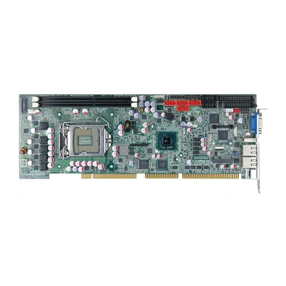
WSB-H610 PICMG 1.0 CPU Card 1.1 Introduction Figure 1-1: WSB-H610 The WSB-H610 PICMG 1.0 CPU card is a Socket LGA1155 32nm Intel® Core ™ i3/i5/i7/Pentium®/Celeron® processor platform that supports two 240-pin 1066/1333 MHz dual-channel DDR3/DDR3L DIMM modules up to 16.0 GB. The WSB-H610 supports two GbE interfaces through the Realtek RTL8111E PCIe Ethernet controllers. -
Page 17: Model Variations
WSB-H610 PICMG 1.0 CPU Card 1.2 Model Variations The model variations of the WSB-H610 are listed below. Model No. CPU Supported DVI-D by 26-pin header WSB-H610-DVI-R10 LGA1155 Intel® Core™ i7/i5/i3/Pentium®/Celeron® LGA1155 Intel® Core™ WSB-H610-R10 i7/i5/i3/Pentium®/Celeron® Table 1-1: WSB-H610 Model Variations 1.3 Features Some of the WSB-H610 motherboard features are listed below: PICMG 1.0 full-size graphics grade solution... -
Page 18: Connectors
WSB-H610 PICMG 1.0 CPU Card 1.4 Connectors The connectors on the WSB-H610 are shown in the figure below. Figure 1-2: Connectors Page 4... -
Page 19: Dimensions
WSB-H610 PICMG 1.0 CPU Card 1.5 Dimensions The main dimensions of the WSB-H610 are shown in the diagram below. Figure 1-3: WSB-H610 Dimensions (mm) Page 5... -
Page 20: Figure 1-4: External Interface Panel Dimensions (Mm)
WSB-H610 PICMG 1.0 CPU Card Figure 1-4: External Interface Panel Dimensions (mm) Page 6... -
Page 21: Data Flow
WSB-H610 PICMG 1.0 CPU Card 1.6 Data Flow F igure 1-5 shows the data flow between the system chipset, the CPU and other components installed on the motherboard. Figure 1-5: Data Flow Diagram Page 7... -
Page 22: Technical Specifications
WSB-H610 PICMG 1.0 CPU Card 1.7 Technical Specifications The WSB-H610 technical specifications are listed below. Specification/Model WSB-H610 PICMG 1.0 Form Factor LGA1155 Intel® Core™ i7/i5/i3/Pentium®/Celeron® CPU CPU Supported Intel® H61 Memory Two 240-pin 1333/1066 MHz dual-channel unbuffered DDR3/DDR3L (1.35V) SDRAM DIMMs support (system max. 16.0 GB) Graphics Engine Intel®... -
Page 23: Table 1-2: Wsb-H610 Specifications
WSB-H610 PICMG 1.0 CPU Card Specification/Model WSB-H610 One 14-pin header (power LED, HDD LED, speaker, power button, Front Panel reset button) One 4-pin wafer connector Infrared One via 5-pin header Keyboard/Mouse One PS/2 keyboard/mouse port One 6-pin wafer connector Parallel Port One parallel port via internal 26-pin box header Serial ATA Four SATA 3Gb/s connectors... -
Page 24: Packing List
WSB-H610 PICMG 1.0 CPU Card Chapter Packing List Page 10... -
Page 25: Anti-Static Precautions
WSB-H610 PICMG 1.0 CPU Card 2.1 Anti-static Precautions WARNING! Static electricity can destroy certain electronics. Make sure to follow the ESD precautions to prevent damage to the product, and injury to the user. Make sure to adhere to the following guidelines: Wear an anti-static wristband: Wearing an anti-static wristband can prevent electrostatic discharge. -
Page 26: Packing List
WSB-H610 PICMG 1.0 CPU Card 2.3 Packing List NOTE: If any of the components listed in the checklist below are missing, do not proceed with the installation. Contact the IEI reseller or vendor the WSB-H610 was purchased from or contact an IEI sales representative directly by sending an email to ales@ieiworld.com. -
Page 27: Optional Items
WSB-H610 PICMG 1.0 CPU Card Quantity Item and Part Number Image DVI-D/USB kit (DVI model only) (P/N: IO-KIT-001-R20) One Key Recovery CD Utility CD Quick Installation Guide Table 2-1: Packing List 2.4 Optional Items The following are optional components which may be separately purchased: Item and Part Number Image RS-422/485 cable, 200 mm... - Page 28 WSB-H610 PICMG 1.0 CPU Card Item and Part Number Image FDD flat cable (P/N: 32200-000017-RS) LPT cable (P/N: 19800-000049-RS) 7.1-channel HD audio kit with Realtek ALC892 audio codec supporting dual audio stream (P/N: AC-KIT-892HD-R10) 20-pin Infineon TPM module (P/N: TPM-IN01-R11) LGA1155/LGA1156 cooler kit (1U chassis compatible, 73W) (P/N: CF-1156A-RS-R11)
-
Page 29: Table 2-2: Optional Items
WSB-H610 PICMG 1.0 CPU Card Item and Part Number Image Intel® Core™ i5-2500T processor (LGA1155, quad core 2.3 GHz, 6M cache, 45W, compatible with CF-1156C-RS CPU cooler kit) (P/N: CPU-DT-i5-2500T) Intel® Core™ i5-2390T processor (LGA1155, dual core 2.7 GHz, 3M cache, 35W, compatible with CF-1156C-RS CPU cooler kit) (P/N: CPU-DT-i5-2390T) Intel®... -
Page 30: Connectors
WSB-H610 PICMG 1.0 CPU Card Chapter Connectors Page 16... -
Page 31: Peripheral Interface Connectors
WSB-H610 PICMG 1.0 CPU Card 3.1 Peripheral Interface Connectors This chapter details all the jumpers and connectors. 3.1.1 WSB-H610 Layout The figures below show all the connectors and jumpers. Figure 3-1: Connectors and Jumpers 3.1.2 Peripheral Interface Connectors The table below lists all the connectors on the board. Connector Type Label... -
Page 32: External Interface Panel Connectors
WSB-H610 PICMG 1.0 CPU Card Connector Type Label DVI-D connector (DVI model only) 26-pin header DVI1 EC SPI flash connector 6-pin wafer JSPI2 Fan connector (CPU) 4-pin wafer CPU_FAN1 Floppy disk drive connector 34-pin box header FDD1 Front panel connector 14-pin header F_PANEL1 I2C connector... -
Page 33: Internal Peripheral Connectors
WSB-H610 PICMG 1.0 CPU Card Connector Type Label USB port USB_C1 VGA connector 15-pin female VGA1 Table 3-2: Rear Panel Connectors 3.2 Internal Peripheral Connectors The section describes all of the connectors on the WSB-H610. 3.2.1 ATX Power Supply Enable Connector CN Label: ATXCTL1 CN Type:... -
Page 34: Audio Kit Connector
WSB-H610 PICMG 1.0 CPU Card 3.2.2 Audio Kit Connector CN Label: J_AUDIO1 10-pin header CN Type: CN Location: See Figure 3-3 CN Pinouts: See Table 3-4 This connector connects to an external audio kit. Figure 3-3: Audio Connector Location Description Description ACZ_SYNC ACZ_BITCLK... -
Page 35: Battery Connector
WSB-H610 PICMG 1.0 CPU Card 3.2.3 Battery Connector CAUTION: Risk of explosion if battery is replaced by an incorrect type. Only certified engineers should replace the on-board battery. Dispose of used batteries according to instructions and local regulations. CN Label: CN Type: 2-pin wafer CN Location:... -
Page 36: Cpu Power Input Connector
WSB-H610 PICMG 1.0 CPU Card 3.2.4 CPU Power Input Connector CN Label: CPU12V1 4-pin Molex power connector CN Type: CN Location: See Figure 3-5 CN Pinouts: See Table 3-6 The connector supports the 12V power supply. Figure 3-5: ATX Power Connector Pinout Location Description Description +12V... -
Page 37: Digital I/O Connector
WSB-H610 PICMG 1.0 CPU Card Figure 3-6: DDR3 DIMM Slot Locations 3.2.6 Digital I/O Connector CN Label: DIO1 CN Type: 10-pin header CN Location: See Figure 3-7 See Table 3-7 CN Pinouts: The digital I/O connector provides programmable input and output for external devices. The digital I/O provides 4-bit output and 4-bit input. -
Page 38: Dvi-D Connector (Dvi Model Only)
WSB-H610 PICMG 1.0 CPU Card Description Description Input 3 Input 2 Input 1 Input 0 Table 3-7: Digital I/O Connector Pinouts 3.2.7 DVI-D Connector (DVI Model Only) CN Label: DVI1 CN Type: 26-pin header CN Location: See Figure 3-8 CN Pinouts: See Table 3-8 The DVI-D connector connects to a monitor that supports DVI video input via the DVI-D/USB kit. -
Page 39: Ec Spi Flash Connector
WSB-H610 PICMG 1.0 CPU Card Description Description CK_DVI_DATA1 CK_DVI_CLK# CK_DVI_CLK Table 3-8: DVI-D Connector Pinouts 3.2.8 EC SPI Flash Connector CN Label: JSPI2 6-pin wafer CN Type: CN Location: See Figure 3-9 CN Pinouts: See Table 3-9 The EC SPI flash connector is for flashing new BIOS onto the embedded controller. -
Page 40: Fan Connector (Cpu)
WSB-H610 PICMG 1.0 CPU Card 3.2.9 Fan Connector (CPU) CN Label: CPU_FAN1 4-pin wafer CN Type: CN Location: See Figure 3-10 CN Pinouts: See Table 3-10 The fan connector attaches to a CPU cooling fan. Figure 3-10: CPU Fan Connector Location Description +12 V Rotation Signal... -
Page 41: Figure 3-11: Floppy Disk Connector Location
WSB-H610 PICMG 1.0 CPU Card Figure 3-11: Floppy Disk Connector Location Description Description DENSEL INDEX- MOTEA- DRVA- DIR- STEP- WDATA- WGATE- TK00- WPT- RDATA- SIDE1- DSKCHG- Table 3-11: Floppy Disk Connector Pinouts Page 27... -
Page 42: Front Panel Connector
WSB-H610 PICMG 1.0 CPU Card 3.2.11 Front Panel Connector CN Label: F_PANEL1 14-pin header CN Type: CN Location: See Figure 3-12 CN Pinouts: See Table 3-12 The front panel connector connects to the indicator LEDs and buttons on the computer's front panel. -
Page 43: I2C Connector
WSB-H610 PICMG 1.0 CPU Card 3.2.12 I2C Connector CN Label: I2C_1 4-pin wafer CN Type: CN Location: See Figure 3-13 CN Pinouts: See Table 3-13 The I2C connector is for system debug. Figure 3-13: I2C Connector Location Description +5VS PCH_GP38_PU PCH_GP39_PU Table 3-13: I2C Connector Pinouts 3.2.13 Infrared Interface Connector... -
Page 44: Keyboard/Mouse Connector
WSB-H610 PICMG 1.0 CPU Card Figure 3-14: Infrared Connector Location Description IR-RX IR-TX Table 3-14: Infrared Connector Pinouts 3.2.14 Keyboard/Mouse Connector CN Label: KB_MS1 CN Type: 6-pin wafer See Figure 3-15 CN Location: CN Pinouts: See Table 3-15 The keyboard/mouse connector connects to a PS/2 Y-cable that can be connected to a PS/2 keyboard and mouse. -
Page 45: Parallel Port Connector
WSB-H610 PICMG 1.0 CPU Card Description +5 VCC Mouse Data Mouse Clock Keyboard Data Keyboard Clock GROUND Table 3-15: Keyboard/Mouse Connector Pinouts 3.2.15 Parallel Port Connector CN Label: LPT1 CN Type: 26-pin box header CN Location: See Figure 3-16 CN Pinouts: See Table 3-16 The parallel port connector connects to a parallel port connector interface or some other parallel port device such as a printer. -
Page 46: Pcie Mini Card Slot
WSB-H610 PICMG 1.0 CPU Card Description Description PPD3 PPD4 PPD5 PPD6 PPD7 BUSY SLCT Table 3-16: Parallel Port Connector Pinouts 3.2.16 PCIe Mini Card Slot CN Label: CN Type: PCIe Mini card slot CN Location: F igure 3-17 See Table 3-17 CN Pinouts: The PCIe Mini card slot is for installing a PCIe Mini expansion card. -
Page 47: Sata 3Gb/S Drive Connectors
WSB-H610 PICMG 1.0 CPU Card Description Description CLKREQ# LFRAME# LAD3 CLK- LAD2 CLK+ LAD1 LAD0 PCIRST# VCC3 PCIRST# PERN2 3VDual PERP2 1.5V SMBCLK PETN2 SMBDATA PETP2 USBD- USBD+ RF_LINK# BLUELED# 1.5V VCC3 Table 3-17: PCIe Mini Card Slot Pinouts 3.2.17 SATA 3Gb/s Drive Connectors CN Label: SATA1, SATA2, SATA3, SATA4 CN Type:... -
Page 48: Serial Port Connectors, Rs-232
WSB-H610 PICMG 1.0 CPU Card The SATA drive connectors can be connected to SATA drives and support up to 3Gb/s data transfer rate. Figure 3-18: SATA 3Gb/s Drive Connector Location Description Description Table 3-18: SATA 3Gb/s Drive Connector Pinouts 3.2.18 Serial Port Connectors, RS-232 CN Label: COM1, COM2 10-pin box header... -
Page 49: Serial Port Connector, Rs-422/485
WSB-H610 PICMG 1.0 CPU Card Figure 3-19: Serial Port Connector Location Description Description DATA CARRIER DETECT (DCD) DATA SET READY (DSR) RECEIVE DATA (RXD) REQUEST TO SEND (RTS) TRANSMIT DATA (TXD) CLEAR TO SEND (CTS) DATA TERMINAL READY (DTR) RING INDICATOR (RI) Table 3-19: Serial Port Connector Pinouts 3.2.19 Serial Port Connector, RS-422/485 CN Label:... -
Page 50: Smbus Connector
WSB-H610 PICMG 1.0 CPU Card Figure 3-20: RS-422/485 Connector Location Description Description RXD422- TXD422+/TXD485+ RXD422+ TXD422-/TXD485- Table 3-20: RS-422/485 Connector Pinouts Use the optional RS-422/485 cable to connect to a serial device. The pinouts of the DB-9 connector are listed below. RS-422 Pinouts RS-485 Pinouts Table 3-21: DB-9 RS-422/485 Pinouts... -
Page 51: Spi Rom Connector
WSB-H610 PICMG 1.0 CPU Card Figure 3-21: SMBus Connector Location Description +5VS SMB_CLK SMB_DATA Table 3-22: SMBus Connector Pinouts 3.2.21 SPI ROM Connector CN Label: JSPI1 8-pin header CN Type: CN Location: See Figure 3-22 CN Pinouts: See Table 3-23 The SPI ROM connector is used to flash new BIOS onto the SPI BIOS chip. -
Page 52: Tpm Connector
WSB-H610 PICMG 1.0 CPU Card Description Description SPI_VCC SPI_CS0 SPI_CLK SPI_MISO SPI_MOSI Table 3-23: SPI ROM Connector Pinouts 3.2.22 TPM Connector CN Label: TPM1 20-pin header CN Type: CN Location: See Figure 3-23 CN Pinouts: See Table 3-24 The TPM connector connects to a TPM module. Figure 3-23: TPM Connector Location Description Description... -
Page 53: Usb Connectors
WSB-H610 PICMG 1.0 CPU Card Description Description SB3V SERIRQ PM_SUS_STAT# DRQ# Table 3-24: TPM Connector Pinouts 3.2.23 USB Connectors CN Label: USB1, USB2, USB3 CN Type: 8-pin header CN Location: See Figure 3-24 CN Pinouts: See Table 3-25 The USB connectors connect to USB devices. Each pin header provides two USB ports. Figure 3-24: USB Connector Pinout Locations Description Description... -
Page 54: External Peripheral Interface Connector Panel
WSB-H610 PICMG 1.0 CPU Card 3.3 External Peripheral Interface Connector Panel The figure below shows the external peripheral interface connector (EPIC) panel. The EPIC panel consists of the following: Figure 3-25: External Peripheral Interface Connector 3.3.1 Ethernet Connectors CN Label: LAN1 and LAN2 CN Type: RJ-45... -
Page 55: Keyboard/Mouse Connector
WSB-H610 PICMG 1.0 CPU Card Description Description on: linked off: 10 Mb/s blinking: data is being sent/received green: 100 Mb/s orange: 1000 Mb/s Table 3-27: Connector LEDs 3.3.2 Keyboard/Mouse Connector CN Label: KB_MS2 CN Type: PS/2 CN Location: See Figure 3-25 See Table 3-28, Figure 3-27 CN Pinouts: The keyboard and mouse connector is a standard PS/2 connector. -
Page 56: Usb Connector
WSB-H610 PICMG 1.0 CPU Card 3.3.3 USB Connector CN Label: USB_C1 USB port CN Type: CN Location: See Figure 3-25 CN Pinouts: See Table 3-29 The WSB-H610 has one external USB 2.0 port. The port connects to both USB 2.0 and USB 1.1 devices. -
Page 57: Figure 3-28: Vga Connector
WSB-H610 PICMG 1.0 CPU Card Description Description HSYNC VSYNC DDCCLK Table 3-30: VGA Connector Pinouts Figure 3-28: VGA Connector Page 43... -
Page 58: Installation
WSB-H610 PICMG 1.0 CPU Card Chapter Installation Page 44... -
Page 59: Anti-Static Precautions
WSB-H610 PICMG 1.0 CPU Card 4.1 Anti-static Precautions WARNING: Failure to take ESD precautions during the installation of the WSB-H610 may result in permanent damage to the WSB-H610 and severe injury to the user. Electrostatic discharge (ESD) can cause serious damage to electronic components, including the WSB-H610. - Page 60 WSB-H610 PICMG 1.0 CPU Card WARNING: The installation instructions described in this manual should be carefully followed in order to prevent damage to the components and injury to the user. Before and during the installation please DO the following: Read the user manual: The user manual provides a complete description of the WSB-H610 installation instructions and configuration options.
-
Page 61: Socket Lga1155 Cpu Installation
WSB-H610 PICMG 1.0 CPU Card 4.2.1 Socket LGA1155 CPU Installation WARNING: CPUs are expensive and sensitive components. When installing the CPU please be careful not to damage it in anyway. Make sure the CPU is installed properly and ensure the correct cooling kit is properly installed. -
Page 62: Figure 4-2: Remove Protective Cover
WSB-H610 PICMG 1.0 CPU Card Figure 4-2: Remove Protective Cover Step 3: Inspect the CPU socket. Make sure there are no bent pins and make sure the socket contacts are free of foreign material. If any debris is found, remove it with compressed air. -
Page 63: Figure 4-3: Insert The Socket Lga1155 Cpu
WSB-H610 PICMG 1.0 CPU Card Figure 4-3: Insert the Socket LGA1155 CPU Step 8: Close the CPU socket. Close the load plate and pull the load lever back a little to have the load plate be able to secure to the knob. Engage the load lever by pushing it back to its original position (Figure 4-4). -
Page 64: Socket Lga1155 Cooling Kit Installation
WSB-H610 PICMG 1.0 CPU Card 4.2.2 Socket LGA1155 Cooling Kit Installation The cooling kit can be bought from IEI. The cooling kit has a heatsink and fan. WARNING: Do not wipe off (accidentally or otherwise) the pre-sprayed layer of thermal paste on the bottom of the heat sink. The thermal paste between the CPU and the heat sink is important for optimum heat dissipation. -
Page 65: Dimm Installation
WSB-H610 PICMG 1.0 CPU Card Step 5: Connect the fan cable. Connect the cooling kit fan cable to the fan connector on the WSB-H610. Carefully route the cable and avoid heat generating chips and fan blades. 4.2.3 DIMM Installation To install a DIMM, please follow the steps below and refer to Figure 4-6. Figure 4-6: DIMM Installation Step 1: Open the DIMM socket handles. -
Page 66: Jumper Settings
WSB-H610 PICMG 1.0 CPU Card 4.3 Jumper Settings NOTE: A jumper is a metal bridge used to close an electrical circuit. It consists of two or three metal pins and a small metal clip (often protected by a plastic cover) that slides over the pins to connect them. -
Page 67: Clear Cmos Jumper
WSB-H610 PICMG 1.0 CPU Card Setting Description Short 1-2 Use ATX power (Default) Short 2-3 Use AT power Table 4-2: AT/ATX Power Mode Jumper Settings Figure 4-7: AT/ATX Power Mode Jumper Location 4.3.2 Clear CMOS Jumper Jumper Label: J_CMOS1 Jumper Type: 3-pin header Jumper Settings: See Table 4-3... -
Page 68: Wake-On Lan Jumper
WSB-H610 PICMG 1.0 CPU Card 4.3.3 Wake-on LAN Jumper CN Label: JLAN_PWR1 6-pin header CN Type: CN Location: See Figure 4-9 CN Pinouts: See Table 4-4 The Wake-on LAN jumper allows the user to enable or disable the Wake-on LAN (WOL) function. -
Page 69: Chassis Installation
WSB-H610 PICMG 1.0 CPU Card 4.4 Chassis Installation 4.4.1 Airflow WARNING: Airflow is critical to the cooling of the CPU and other onboard components. The chassis in which the WSB-H610 must have air vents to allow cool air to move into the system and hot air to move out. The WSB-H610 must be installed in a chassis with ventilation holes on the sides allowing airflow to travel through the heat sink surface. -
Page 70: Dvi-D/Usb Kit Installation (Dvi Model Only)
WSB-H610 PICMG 1.0 CPU Card Step 2: Insert the cable connectors. Insert one connector into each serial port box headers (Figure 4-10). A key on the front of the cable connectors ensures the connector can only be installed in one direction. Figure 4-10: Dual RS-232 Cable Installation Step 3: Secure the bracket. -
Page 71: Sata Drive Connection
WSB-H610 PICMG 1.0 CPU Card Figure 4-11: DVI-D/USB Kit Installation Step 3: Mount the DVI-D/USB kit onto the chassis. Once the DVI-D/USB kit is connected to the board, secure the DVI-D/USB kit bracket to the system chassis. 4.5.3 SATA Drive Connection The WSB-H610 is shipped with four SATA drive cables. -
Page 72: Figure 4-12: Sata Drive Cable Connection
WSB-H610 PICMG 1.0 CPU Card Figure 4-12: SATA Drive Cable Connection Step 3: Connect the cable to the SATA disk. Connect the connector on the other end of the cable to the connector at the back of the SATA drive. See Figure 4-13. Step 4: Connect the SATA power cable (optional). -
Page 73: Usb Cable (Dual Port) With Slot Bracket
WSB-H610 PICMG 1.0 CPU Card Figure 4-13: SATA Power Drive Connection 4.5.4 USB Cable (Dual Port) with Slot Bracket The WSB-H610 is shipped with a dual port USB 2.0 cable. To connect the USB cable connector, please follow the steps below. Step 1: Locate the connectors. -
Page 74: Pcie Mini Card Installation
WSB-H610 PICMG 1.0 CPU Card Step 3: Insert the cable connectors. Once the cable connectors are properly aligned with the USB connectors on the WSB-H610, connect the cable connectors to the on-board connectors. See Figure 4-14. Figure 4-14: Dual USB Cable Connection Step 4: Attach the bracket to the chassis. -
Page 75: External Peripheral Interface Connection
WSB-H610 PICMG 1.0 CPU Card Figure 4-15: PCIe Mini Card Installation Step 1: Insert into the socket at and angle. Line up the notch on the card with the notch on the connector. Slide the PCIe Mini card into the socket at an angle of about 20º. -
Page 76: Usb Device Connection (Single Connector)
WSB-H610 PICMG 1.0 CPU Card Figure 4-16: LAN Connection Step 3: Insert the LAN cable RJ-45 connector. Once aligned, gently insert the LAN cable RJ-45 connector into the on-board RJ-45 connector. 4.6.2 USB Device Connection (Single Connector) There is one external USB 2.0 connector. The connector is perpendicular to the WSB-H610. -
Page 77: Vga Monitor Connection
WSB-H610 PICMG 1.0 CPU Card Figure 4-17: USB Device Connection Step 3: Insert the device connector. Once aligned, gently insert the USB device connector into the on-board connector. 4.6.3 VGA Monitor Connection The WSB-H610 has a single female DB-15 connector on the external peripheral interface panel. -
Page 78: Figure 4-18: Vga Connector
WSB-H610 PICMG 1.0 CPU Card Figure 4-18: VGA Connector Step 4: Secure the connector. Secure the DB-15 VGA connector from the VGA monitor to the external interface by tightening the two retention screws on either side of the connector. Page 64... -
Page 79: Bios
WSB-H610 PICMG 1.0 CPU Card Chapter BIOS Page 65... -
Page 80: Introduction
WSB-H610 PICMG 1.0 CPU Card 5.1 Introduction The BIOS is programmed onto the BIOS chip. The BIOS setup program allows changes to certain system settings. This chapter outlines the options that can be changed. NOTE: Some of the BIOS options may vary throughout the life cycle of the product and are subject to change without prior notice. -
Page 81: Getting Help
WSB-H610 PICMG 1.0 CPU Card Function Decrease the numeric value or make changes Page Up key Increase the numeric value or make changes Page Dn key Decrease the numeric value or make changes Esc key Main Menu – Quit and not save changes into CMOS Status Page Setup Menu and Option Page Setup Menu -- Exit current page and return to Main Menu General help, only for Status Page Setup Menu and Option... -
Page 82: Main
WSB-H610 PICMG 1.0 CPU Card Save & Exit – Selects exit options and loads default settings The following sections completely describe the configuration options found in the menu items at the top of the BIOS screen and listed above. 5.2 Main The Main BIOS menu (BIOS Menu 1) appears when the BIOS Setup program is entered. -
Page 83: Advanced
WSB-H610 PICMG 1.0 CPU Card Memory Information The Memory Information lists a brief summary of the on-board memory. The fields in Memory Information cannot be changed. Total Memory: Displays the auto-detected system memory size and type. The System Overview field also has two user configurable fields: System Date [xx/xx/xx] Use the System Date option to set the system date. -
Page 84: Acpi Settings
WSB-H610 PICMG 1.0 CPU Card Aptio Setup Utility – Copyright (C) 2011 American Megatrends, Inc. Main Advanced Chipset Boot Security Save & Exit > ACPI Settings System ACPI Parameters > Trusted Computing > CPU Configuration > SATA Configuration > Intel TXT(LT) Configuration ---------------------- >... -
Page 85: Trusted Computing
WSB-H610 PICMG 1.0 CPU Card ACPI Sleep State [S1 (CPU Stop Clock)] Use the ACPI Sleep State option to specify the sleep state the system enters when it is not being used. (CPU Stop The system enters S1 (POS) sleep state. The EFAULT Clock) system appears off. -
Page 86: Cpu Configuration
WSB-H610 PICMG 1.0 CPU Card TPM Support [Disable] Use the TPM Support option to configure support for the TPM. TPM support is disabled. Disable EFAULT Enable TPM support is enabled. 5.3.3 CPU Configuration Use the CPU Configuration menu (BIOS Menu 5) to enter the CPU Information submenu or enable Intel Virtualization Technology. -
Page 87: Cpu Information
WSB-H610 PICMG 1.0 CPU Card 5.3.3.1 CPU Information Use the CPU Information submenu (BIOS Menu 6) to view detailed CPU specifications and configure the CPU. Aptio Setup Utility – Copyright (C) 2011 American Megatrends, Inc. Advanced CPU Information Intel(R) Core(TM) i5-2400 CPU 0 @ 3.10GHz CPU Signature 206a7 ----------------------... -
Page 88: Sata Configuration
WSB-H610 PICMG 1.0 CPU Card L2 Cache: Lists the amount of storage space on the L2 cache. L3 Cache: Lists the amount of storage space on the L3 cache. 5.3.4 SATA Configuration Use the SATA Configuration menu (BIOS Menu 7) to change and/or set the configuration of the SATA devices installed in the system. -
Page 89: Intel Txt(Lt) Configuration
WSB-H610 PICMG 1.0 CPU Card storage devices. Some legacy OS do not support this mode. Compatible Configures the on-board ATA controller to be in EFAULT compatible mode. In this mode, a SATA channel will replace one of the IDE channels. This mode supports up to 4 storage devices. -
Page 90: Usb Configuration
WSB-H610 PICMG 1.0 CPU Card 5.3.6 USB Configuration Use the USB Configuration menu (BIOS Menu 9) to read USB configuration information and configure the USB settings. Aptio Setup Utility – Copyright (C) 2011 American Megatrends, Inc. Advanced USB Configuration Enables Legacy USB support. -
Page 91: Super Io Configuration
WSB-H610 PICMG 1.0 CPU Card Enabled Legacy USB support enabled EFAULT Legacy USB support disabled Disabled Auto Legacy USB support is disabled if no USB devices are connected. 5.3.7 Super IO Configuration Use the Super IO Configuration menu (BIOS Menu 10) to set or change the configurations for the FDD controllers, parallel ports and serial ports. -
Page 92: Floppy Disk Controller Configuration
WSB-H610 PICMG 1.0 CPU Card 5.3.7.1 Floppy Disk Controller Configuration Use the Floppy Disk Controller Configuration menu (BIOS Menu 12) to configure the floppy disk controller. Aptio Setup Utility – Copyright (C) 2011 American Megatrends, Inc. Advanced Floppy Disk Controller Configuration Enable or Disable Floppy Disk Controller Floppy Disk Controller... -
Page 93: Bios Menu 12: Serial Port N Configuration Menu
WSB-H610 PICMG 1.0 CPU Card Aptio Setup Utility – Copyright (C) 2011 American Megatrends, Inc. Advanced Serial Port n Configuration Enable or Disable Serial Port (COM) Serial Port [Enabled] Device Settings IO=3F8h; IRQ=4 --------------------- Change Settings [Auto] : Select Screen ↑... - Page 94 WSB-H610 PICMG 1.0 CPU Card IO=2F8h; Serial Port I/O port address is 2F8h and the interrupt IRQ=3, 4 address is IRQ3, 4 Serial Port I/O port address is 2C0h and the interrupt IO=2C0h; address is IRQ3, 4 IRQ=3, 4 IO=2C8h; Serial Port I/O port address is 2C8h and the interrupt IRQ=3, 4 address is IRQ3, 4...
- Page 95 WSB-H610 PICMG 1.0 CPU Card 5.3.7.2.3 Serial Port 3 Configuration Serial Port [Enabled] Use the Serial Port option to enable or disable the serial port. Disabled Disable the serial port Enable the serial port Enabled EFAULT Change Settings [Auto] Use the Change Settings option to change the serial port IO port address and interrupt address.
- Page 96 WSB-H610 PICMG 1.0 CPU Card 5.3.7.2.4 IrDA Configuration Serial Port [Enabled] Use the Serial Port option to enable or disable the serial port. Disabled Disable the serial port Enable the serial port Enabled EFAULT Change Settings [Auto] Use the Change Settings option to change the serial port IO port address and interrupt address.
-
Page 97: Parallel Port Configuration
WSB-H610 PICMG 1.0 CPU Card 5.3.7.3 Parallel Port Configuration Use the Parallel Port Configuration menu (BIOS Menu 12) to configure the serial port n. Aptio Setup Utility – Copyright (C) 2010 American Megatrends, Inc. Advanced Parallel Port Configuration Enable or Disable Parallel Port (LPT/LPTE) Parallel Port [Enabled]... -
Page 98: H/W Monitor
WSB-H610 PICMG 1.0 CPU Card IO=278h; Parallel Port I/O port address is 278h and the IRQ=7 interrupt address is IRQ7 Parallel Port I/O port address is 3BCh and the IO=3BCh; interrupt address is IRQ7 IRQ=7 Device Mode [Printer Mode] Use the Device Mode option to select the mode the parallel port operates in. Configuration options are listed below. -
Page 99: Bios Menu 14: H/W Monitor
WSB-H610 PICMG 1.0 CPU Card Aptio Setup Utility – Copyright (C) 2011 American Megatrends, Inc. Advanced PC Health Status Smart FAN Configuration CPU Temperature :+52 C Accuracy: 1.(-5~+10) degree around 100 degree 2.(-10~+15) degree around 50 degree SYS Temperature :+34 C CPU_FAN1 Speed :2255 RPM ---------------------... -
Page 100: Cpu_Fan 1 Configuration
WSB-H610 PICMG 1.0 CPU Card 5.3.8.1 CPU_FAN 1 Configuration Use the CPU_FAN 1 Configuration submenu (BIOS Menu 15) to configure fan 1 temperature and speed settings. Aptio Setup Utility – Copyright (C) 2011 American Megatrends, Inc. Advanced Smart Fan Mode Configuration CPU Smart Fan control [Auto by RPM] CPU Temperature 1... -
Page 101: Serial Port Console Redirection
WSB-H610 PICMG 1.0 CPU Card 5.3.9 Serial Port Console Redirection The Serial Port Console Redirection menu (BIOS Menu 16) allows the console redirection options to be configured. Console redirection allows users to maintain a system remotely by re-directing keyboard input and text output through the serial port. Aptio Setup Utility –... - Page 102 WSB-H610 PICMG 1.0 CPU Card Bits per second [115200] Use the Bits per second option to specify the serial port transmission speed. The speed must match the other side. Long or noisy lines may require lower speeds. 9600 Sets the serial port transmission speed at 9600. Sets the serial port transmission speed at 19200.
-
Page 103: Iei Feature
WSB-H610 PICMG 1.0 CPU Card Stop Bits [1] Use the Stop Bits option to specify the number of stop bits used to indicate the end of a serial data packet. Communication with slow devices may require more than 1 stop bit. Sets the number of stop bits at 1. -
Page 104: Chipset
WSB-H610 PICMG 1.0 CPU Card Aptio Setup Utility – Copyright (C) 2011 American Megatrends, Inc. Advanced iEi Feature Auto Recovery Function Reboot and recover Auto Recovery Function [Disabled] system automatically within 10 min, when OS crashes. Please install Auto Recovery API service before enabling this function. -
Page 105: Northbridge Configuration
WSB-H610 PICMG 1.0 CPU Card Aptio Setup Utility – Copyright (C) 2011 American Megatrends, Inc. Main Advanced Chipset Boot Security Save & Exit > North Bridge North Bridge Parameters > South Bridge > Integrated Graphics --------------------- : Select Screen ↑ ↓: Select Item Enter Select +/-: Change Opt. - Page 106 WSB-H610 PICMG 1.0 CPU Card of PCI graphics controller, a PCI express (PEG) controller or an IGD. Configuration options are listed below: PEG/IGD/PCI EFAULT IGD Memory [64M] Use the IGD Memory option to specify the amount of system memory that can be used by the internal graphics device.
- Page 107 WSB-H610 PICMG 1.0 CPU Card 416M 416 MB of memory used by internal graphics device 448 MB of memory used by internal graphics 448M device 480M 480 MB of memory used by internal graphics device 512M 512 MB of memory used by internal graphics device PEG Force Gen1 [Enabled] Use the PEG Force Gen1 option to force the PCI Express port to run at Gen1 speed.
-
Page 108: Southbridge Configuration
WSB-H610 PICMG 1.0 CPU Card 5.4.2 Southbridge Configuration Use the South Bridge menu (BIOS Menu 20) to configure the Southbridge chipset. Aptio Setup Utility – Copyright (C) 2011 American Megatrends, Inc. Chipset SouthBridge Configuration Specify what state to go to when power is Auto Power Button Status [OFF] re-applied after a power... -
Page 109: Integrated Graphics
WSB-H610 PICMG 1.0 CPU Card 5.4.3 Integrated Graphics Use the Integrated Graphics menu (BIOS Menu 21) to configure the video device connected to the system. Aptio Setup Utility – Copyright (C) 2011 American Megatrends, Inc. Advanced Intel IGD SWSCI OpRegion Configuration Select DVMT Mode used by Internal Graphics DVMT Mode Select... -
Page 110: Boot
WSB-H610 PICMG 1.0 CPU Card DVMT Memory [Maximum] Use the DVMT Memory option to specify the maximum amount of memory that can be allocated as graphics memory. Configuration options are listed below. 128 MB 256 MB Maximum EFAULT IGD - Boot Type [AUTO] Use the IGD - Boot Type option to select the display device used by the system when it boots. - Page 111 WSB-H610 PICMG 1.0 CPU Card Bootup NumLock State [On] Use the Bootup NumLock State BIOS option to specify if the number lock setting must be modified during boot up. Allows the Number Lock on the keyboard to be EFAULT enabled automatically when the computer system boots up.
-
Page 112: Security
WSB-H610 PICMG 1.0 CPU Card Option ROM Messages [Force BIOS] Use the Option ROM Messages option to set the Option ROM display mode. Sets display mode to force BIOS. Force EFAULT BIOS Sets display mode to current. Keep Current 5.6 Security Use the Security menu (BIOS Menu 23) to set system and user passwords. -
Page 113: Exit
WSB-H610 PICMG 1.0 CPU Card 5.7 Exit Use the Exit menu (BIOS Menu 24) to load default BIOS values, optimal failsafe values and to save configuration changes. Aptio Setup Utility – Copyright (C) 2011 American Megatrends, Inc. Main Advanced Chipset Boot Security Save &... - Page 114 WSB-H610 PICMG 1.0 CPU Card Save as User Defaults Use the Save as User Defaults option to save the changes done so far as user defaults. Restore User Defaults Use the Restore User Defaults option to restore the user defaults to all the setup options. Page 100...
-
Page 115: Software Drivers
WSB-H610 PICMG 1.0 CPU Card Chapter Software Drivers Page 101... -
Page 116: Available Software Drivers
WSB-H610 PICMG 1.0 CPU Card 6.1 Available Software Drivers NOTE: The content of the CD may vary throughout the life cycle of the product and is subject to change without prior notice. Visit the IEI website or contact technical support for the latest updates. The following drivers can be installed on the system: Chipset Graphic... -
Page 117: Figure 6-1: Introduction Screen
WSB-H610 PICMG 1.0 CPU Card Figure 6-1: Introduction Screen Step 3: Click WSB-H610. Step 4: A new screen with a list of available drivers appears (Figure 6-2). Figure 6-2: Available Drivers Page 103... -
Page 118: Chipset Driver Installation
WSB-H610 PICMG 1.0 CPU Card Step 5: Install all of the necessary drivers in this menu. 6.3 Chipset Driver Installation To install the chipset driver, please do the following. Step 1: Access the driver list. (See Section 6.2) Step 2: Click “Chipset”. -
Page 119: Figure 6-4: Chipset Driver Welcome Screen
WSB-H610 PICMG 1.0 CPU Card Figure 6-4: Chipset Driver Welcome Screen Step 7: The license agreement in Figure 6-5 appears. Step 8: Read the License Agreement. Step 9: Click Yes to continue. Figure 6-5: Chipset Driver License Agreement Step 10: The Read Me file in Figure 6-6 appears. -
Page 120: Figure 6-6: Chipset Driver Read Me File
WSB-H610 PICMG 1.0 CPU Card Step 11: Click Next to continue. Figure 6-6: Chipset Driver Read Me File Step 12: Setup Operations are performed as shown in Figure 6-7. Step 13: Once the Setup Operations are complete, click Next to continue. Figure 6-7: Chipset Driver Setup Operations Page 106... -
Page 121: Graphics Driver Installation
WSB-H610 PICMG 1.0 CPU Card Step 14: The Finish screen in Figure 6-8 appears. Step 15: Select “Yes, I want to restart this computer now” and click Finish. Figure 6-8: Chipset Driver Installation Finish Screen 6.4 Graphics Driver Installation To install the Graphics driver, please do the following. Step 1: Access the driver list. -
Page 122: Figure 6-9: Graphics Driver Welcome Screen
WSB-H610 PICMG 1.0 CPU Card Figure 6-9: Graphics Driver Welcome Screen Step 6: The License Agreement in Figure 6-10 appears. Step 7: Click Yes to accept the agreement and continue. Figure 6-10: Graphics Driver License Agreement Step 8: Setup Operations are performed as shown in Figure 6-11. Page 108... -
Page 123: Figure 6-11: Graphics Driver Setup Operations
WSB-H610 PICMG 1.0 CPU Card Step 9: Once the Setup Operations are complete, click Next to continue. Figure 6-11: Graphics Driver Setup Operations Step 10: The Finish screen in Figure 6-12 appears. Step 11: Select “Yes, I want to restart this computer now” and click Finish. Figure 6-12: Graphics Driver Installation Finish Screen Page 109... -
Page 124: Lan Driver Installation
WSB-H610 PICMG 1.0 CPU Card 6.5 LAN Driver Installation To install the LAN driver, please do the following. Step 1: Access the driver list. (See Section 6.2) Step 2: Click “LAN”. Step 3: Locate the Autorun file and double click it. Step 4: The Welcome screen in Figure 6-13 appears. -
Page 125: Figure 6-14: Lan Driver Installation
WSB-H610 PICMG 1.0 CPU Card Figure 6-14: LAN Driver Installation Step 8: The program begins to install. Step 9: When the driver installation is complete, the screen in Figure 6-15 appears. Step 10: Click Finish to exit. Figure 6-15: LAN Driver Installation Complete Page 111... -
Page 126: Audio Driver Installation
WSB-H610 PICMG 1.0 CPU Card 6.6 Audio Driver Installation To install the audio driver, please do the following. Step 1: Access the driver list. (See Section 6.2) Step 2: Click “Audio” and select the folder which corresponds to the operating system. Step 3: Double click the setup file. -
Page 127: Figure 6-17: Audio Driver Installation Welcome Screen
WSB-H610 PICMG 1.0 CPU Card Figure 6-17: Audio Driver Installation Welcome Screen Step 7: The driver installation begins. See Figure 6-18. Figure 6-18: Audio Driver Installation Step 8: When the driver is installed, the driver installation finish screen in Figure 6-19 appears. -
Page 128: A Regulatory Compliance
WSB-H610 PICMG 1.0 CPU Card Appendix Regulatory Compliance Page 114... - Page 129 WSB-H610 PICMG 1.0 CPU Card DECLARATION OF CONFORMITY This equipment has been tested and found to comply with specifications for CE marking. If the user modifies and/or installs other devices in the equipment, the CE conformity declaration may no longer apply. FCC WARNING This equipment complies with Part 15 of the FCC Rules.
-
Page 130: Bbios Options
WSB-H610 PICMG 1.0 CPU Card Appendix BIOS Options Page 116... - Page 131 WSB-H610 PICMG 1.0 CPU Card Below is a list of BIOS configuration options in the BIOS chapter. System Overview .........................68 Memory Information ......................69 System Date [xx/xx/xx] ......................69 System Time [xx:xx:xx] .......................69 ACPI Sleep State [S1 (CPU Stop Clock)] ................71 ...
- Page 132 WSB-H610 PICMG 1.0 CPU Card Stop Bits [1] ..........................89 Flow Control [None]......................89 Auto Recovery Function [Disabled]...................90 Initiate Graphic Adapter [PEG/IGD/PCI]................91 IGD Memory [64M] .......................92 PEG Force Gen1 [Enabled] ....................93 Detect Non-Compliance Device [Enabled] ................93 ...
-
Page 133: C Terminology
WSB-H610 PICMG 1.0 CPU Card Appendix Terminology Page 119... - Page 134 WSB-H610 PICMG 1.0 CPU Card AC ’97 Audio Codec 97 (AC’97) refers to a codec standard developed by Intel® in 1997. ACPI Advanced Configuration and Power Interface (ACPI) is an OS-directed configuration, power management, and thermal management interface. AHCI Advanced Host Controller Interface (AHCI) is a SATA Host controller register-level interface.
- Page 135 WSB-H610 PICMG 1.0 CPU Card DIMM Dual Inline Memory Modules are a type of RAM that offer a 64-bit data bus and have separate electrical contacts on each side of the module. The digital inputs and digital outputs are general control signals that control the on/off circuit of external devices or TTL devices.
- Page 136 WSB-H610 PICMG 1.0 CPU Card LVDS Low-voltage differential signaling (LVDS) is a dual-wire, high-speed differential electrical signaling system commonly used to connect LCD displays to a computer. POST The Power-on Self Test (POST) is the pre-boot actions the system performs when the system is turned-on. Random Access Memory (RAM) is volatile memory that loses data when power is lost.
-
Page 137: D Digital I/O Interface
WSB-H610 PICMG 1.0 CPU Card Appendix Digital I/O Interface Page 123... -
Page 138: Introduction
WSB-H610 PICMG 1.0 CPU Card D.1 Introduction The DIO connector on the WSB-H610 is interfaced to GPIO ports on the Super I/O chipset. The DIO has both 4-bit digital inputs and 4-bit digital outputs. The digital inputs and digital outputs are generally control signals that control the on/off circuit of external devices or TTL devices. -
Page 139: Assembly Language Sample 1
WSB-H610 PICMG 1.0 CPU Card D.2 Assembly Language Sample 1 AX, 6F08H ;setting the digital port as input AL low byte = value AH – 6FH Sub-function: AL – 9 :Set the digital port as OUTPUT :Digital I/O input value D.3 Assembly Language Sample 2 AX, 6F09H ;setting the digital port as output... -
Page 140: E Watchdog Timer
WSB-H610 PICMG 1.0 CPU Card Appendix Watchdog Timer Page 126... - Page 141 WSB-H610 PICMG 1.0 CPU Card NOTE: The following discussion applies to DOS environment. Contact IEI support or visit the IEI website for specific drivers for other operating systems. The Watchdog Timer is provided to ensure that standalone systems can always recover from catastrophic conditions that cause the CPU to crash.
- Page 142 WSB-H610 PICMG 1.0 CPU Card NOTE: When exiting a program it is necessary to disable the Watchdog Timer, otherwise the system resets. EXAMPLE PROGRAM: ; INITIAL TIMER PERIOD COUNTER W_LOOP: AX, 6F02H ;setting the time-out value BL, 30 ;time-out value is 48 seconds ;...
-
Page 143: F Hazardous Materials Disclosure
WSB-H610 PICMG 1.0 CPU Card Appendix Hazardous Materials Disclosure Page 129... -
Page 144: Hazardous Materials Disclosure Table For Ipb Products Certified As Rohs Compliant Under 2002/95/Ec Without Mercury
WSB-H610 PICMG 1.0 CPU Card F.1 Hazardous Materials Disclosure Table for IPB Products Certified as RoHS Compliant Under 2002/95/EC Without Mercury The details provided in this appendix are to ensure that the product is compliant with the Peoples Republic of China (China) RoHS standards. The table below acknowledges the presences of small quantities of certain materials in the product, and is applicable to China RoHS only. - Page 145 WSB-H610 PICMG 1.0 CPU Card Part Name Toxic or Hazardous Substances and Elements Lead Mercury Cadmium Hexavalent Polybrominated Polybrominated Biphenyls Diphenyl (Pb) (Hg) (Cd) Chromium (CR(VI)) (PBB) Ethers (PBDE) Housing Display Printed Circuit Board Metal Fasteners Cable Assembly Fan Assembly Power Supply Assemblies Battery...
- Page 146 WSB-H610 PICMG 1.0 CPU Card 此附件旨在确保本产品符合中国 RoHS 标准。以下表格标示此产品中某有毒物质的含量符 合中国 RoHS 标准规定的限量要求。 本产品上会附有”环境友好使用期限”的标签,此期限是估算这些物质”不会有泄漏或突变”的 年限。本产品可能包含有较短的环境友好使用期限的可替换元件,像是电池或灯管,这些元 件将会单独标示出来。 部件名称 有毒有害物质或元素 铅 汞 镉 六价铬 多溴联苯 多溴二苯 醚 (Pb) (Hg) (Cd) (CR(VI)) (PBB) (PBDE) 壳体 显示 印刷电路板 金属螺帽 电缆组装 风扇组装 电力供应组装 电池 O: 表示该有毒有害物质在该部件所有物质材料中的含量均在 SJ/T11363-2006 标准规定的限量要求以下。 X: 表示该有毒有害物质至少在该部件的某一均质材料中的含量超出...
Need help?
Do you have a question about the WSB-H610-R11 and is the answer not in the manual?
Questions and answers