IEI Technology SPCIE-C2260-i2 User Manual
Full-size picmzg 1.3 cpu card
Hide thumbs
Also See for SPCIE-C2260-i2:
- Quick installation manual (18 pages) ,
- User manual (162 pages)
Table of Contents
Advertisement
Quick Links
SPCIE-C2260-i2 PICMG 1.3 CPU Card
MODEL:
SPCIE-C2260-i2
Full-Size PICMG 1.3 CPU Card Supports LGA1150 Intel®
Xeon® E3, Core™ i3, Pentium® or Celeron® CPU, Intel® C226
Chipset, DDR3, VGA, iDP, Dual Intel® PCIe GbE, SATA 6Gb/s,
PCIe Mini, mSATA, RS-232, HD Audio, iRIS-2400 and RoHS
User Manual
Page i
Rev. 1.00 – 14 January, 2014
Advertisement
Table of Contents

Subscribe to Our Youtube Channel
Related Manuals for IEI Technology SPCIE-C2260-i2


Summary of Contents for IEI Technology SPCIE-C2260-i2
- Page 1 SPCIE-C2260-i2 PICMG 1.3 CPU Card MODEL: SPCIE-C2260-i2 Full-Size PICMG 1.3 CPU Card Supports LGA1150 Intel® Xeon® E3, Core™ i3, Pentium® or Celeron® CPU, Intel® C226 Chipset, DDR3, VGA, iDP, Dual Intel® PCIe GbE, SATA 6Gb/s, PCIe Mini, mSATA, RS-232, HD Audio, iRIS-2400 and RoHS...
- Page 2 SPCIE-C2260-i2 PICMG 1.3 CPU Card Revision Date Version Changes 1.00 Initial release 14 January, 2014 Page ii...
- Page 3 SPCIE-C2260-i2 PICMG 1.3 CPU Card Copyright COPYRIGHT NOTICE The information in this document is subject to change without prior notice in order to improve reliability, design and function and does not represent a commitment on the part of the manufacturer.
-
Page 4: Table Of Contents
SPCIE-C2260-i2 PICMG 1.3 CPU Card Table of Contents 1 INTRODUCTION......................1 1.1 I ......................2 NTRODUCTION 1.2 F ........................3 EATURES 1.3 C ......................4 ONNECTORS 1.4 D ....................... 5 IMENSIONS 1.5 D ........................ 6 1.6 T ..................7 ECHNICAL PECIFICATIONS 2 PACKING LIST ...................... - Page 5 SPCIE-C2260-i2 PICMG 1.3 CPU Card 3.2.12 Internal DisplayPort Connector ..............27 3.2.13 Infrared Interface Connector ................. 28 3.2.14 iRIS Module Slot .................... 29 3.2.15 Keyboard and Mouse Connector ..............30 3.2.16 LAN LED Connectors ..................31 3.2.17 Parallel Port Connector ................31 3.2.18 PCIe Mini Card Slot ..................
- Page 6 SPCIE-C2260-i2 PICMG 1.3 CPU Card 4.4.1 Airflow......................57 4.4.2 CPU Card Installation ..................57 4.5 I ............57 NTERNAL ERIPHERAL EVICE ONNECTIONS 4.5.1 Dual RS-232 Cable with Slot Bracket.............. 57 4.5.2 iRIS Module Installation .................. 58 4.5.3 SATA Drive Connection ................... 59 4.5.4 USB Cable (Dual Port) with Slot Bracket ............
- Page 7 SPCIE-C2260-i2 PICMG 1.3 CPU Card 5.3.9.1 Serial Port n Configuration ............... 87 5.3.9.2 Parallel Port Configuration ............... 91 5.3.10 F81866 H/W Monitor..................93 5.3.10.1 Smart Fan Mode Configuration .............. 94 5.3.11 Serial Port Console Redirection..............95 5.3.12 iEi Feature ..................... 98 5.4 C...
- Page 8 SPCIE-C2260-i2 PICMG 1.3 CPU Card B.2.2 Create Partitions ................... 146 B.2.3 Install Operating System, Drivers and Applications ........150 B.2.4 Build-up Recovery Partition................151 B.2.5 Create Factory Default Image............... 153 B.3 A ..............158 ECOVERY ETUP ROCEDURE B.4 S ................163...
- Page 9 SPCIE-C2260-i2 PICMG 1.3 CPU Card F.3 A ® M .......... 195 CCESSING THE NTEL ATRIX TORAGE ANAGER F.4 I RAID A ........196 NSTALLING THE PERATING YSTEM TO THE RRAY G HAZARDOUS MATERIALS DISCLOSURE ............197 G.1 H IPB P...
- Page 10 SPCIE-C2260-i2 PICMG 1.3 CPU Card List of Figures Figure 1-1: SPCIE-C2260-i2 ......................2 Figure 1-2: Connectors ........................4 Figure 1-3: SPCIE-C2260-i2 Dimensions (mm) ................5 Figure 1-4: Data Flow Diagram......................6 Figure 3-1: Connectors and Jumpers..................16 Figure 3-2: ATX Power Connector Pinout Location..............19 Figure 3-3: Audio Connector Location ..................20 Figure 3-4: Battery Connector Location..................21...
- Page 11 SPCIE-C2260-i2 PICMG 1.3 CPU Card Figure 3-27: USB 2.0 Connector Pinout Locations ..............40 Figure 3-28: USB 3.0 Connector Location .................41 Figure 3-29: External Peripheral Interface Connector ..............42 Figure 3-30: Ethernet Connector....................42 Figure 3-31: VGA Connector .......................44 Figure 4-1: Disengage the CPU Socket Load Lever..............48 Figure 4-2: Remove Protective Cover..................49...
- Page 12 SPCIE-C2260-i2 PICMG 1.3 CPU Card Figure 6-8: Graphics Driver Welcome Screen ................ 121 Figure 6-9: Graphics Driver License Agreement..............122 Figure 6-10: Graphics Driver Read Me File ................122 Figure 6-11: Graphics Driver Setup Operations ..............123 Figure 6-12: Graphics Driver Installation Finish Screen ............123 Figure 6-13: Intel®...
- Page 13 SPCIE-C2260-i2 PICMG 1.3 CPU Card Figure B-13: Symantec Ghost Path ..................154 Figure B-14: Select a Local Source Drive ................155 Figure B-15: Select a Source Partition from Basic Drive ............155 Figure B-16: File Name to Copy Image to ................156 Figure B-17: Compress Image....................
- Page 14 SPCIE-C2260-i2 PICMG 1.3 CPU Card List of Tables Table 1-1: SPCIE-C2260-i2 Specifications ...................9 Table 2-1: Packing List.........................13 Table 2-2: Optional Items......................14 Table 3-1: Peripheral Interface Connectors ................18 Table 3-2: Rear Panel Connectors ....................18 Table 3-3: ATX Power Connector Pinouts .................19 Table 3-4: Audio Connector Pinouts ..................20...
- Page 15 SPCIE-C2260-i2 PICMG 1.3 CPU Card Table 3-28: USB 2.0 Connector Pinouts ..................41 Table 3-29: USB 3.0 Connector Pinouts ..................41 Table 3-30: LAN Pinouts ......................42 Table 3-31: Connector LEDs......................43 Table 3-32: USB 3.0 Port Pinouts....................43 Table 3-33: VGA Connector Pinouts...................44 Table 4-1: AT/ATX Power Mode Switch Settings...............54 Table 4-2: Flash Descriptor Security Override Jumper Settings..........55...
- Page 16 SPCIE-C2260-i2 PICMG 1.3 CPU Card BIOS Menus BIOS Menu 1: Main ........................75 BIOS Menu 2: Advanced ......................77 BIOS Menu 3: ACPI Configuration ....................77 BIOS Menu 4: RTC Wake Settings ....................79 BIOS Menu 5: Trusted Computing ....................80 BIOS Menu 6: CPU Configuration ....................81 BIOS Menu 7: SATA Configuration .....................82...
- Page 17 SPCIE-C2260-i2 PICMG 1.3 CPU Card BIOS Menu 31: IEI Feature......................163 SPCIE-C2260-i2 Page xvii...
-
Page 18: Introduction
SPCIE-C2260-i2 PICMG 1.3 CPU Card Chapter Introduction Page 1... -
Page 19: Introduction
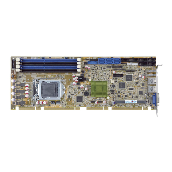
1.1 Introduction Figure 1-1: SPCIE-C2260-i2 The SPCIE-C2260-i2 is a PICMG 1.3 CPU card. It accepts a Socket LGA1150 Intel® Xeon® E3, Core™ i3, Pentium® or Celeron® processor and supports four 240-pin 1600/1333 MHz dual-channel DDR3 DIMM modules up to 32 GB. -
Page 20: Features
SPCIE-C2260-i2 PICMG 1.3 CPU Card 1.2 Features Some of the SPCIE-C2260-i2 motherboard features are listed below: PICMG 1.3 full-size solution LGA1150 Intel® Xeon® E3, Core™ i3, Pentium® or Celeron® processor supported Intel® C226 chipset Four 240-pin 1600/1333 MHz dual-channel DDR3 DIMMs support up to 32 GB Dual independent display by VGA and iDP interfaces Supports IPMI 2.0 via iRIS-2400 module... -
Page 21: Connectors
SPCIE-C2260-i2 PICMG 1.3 CPU Card 1.3 Connectors The connectors on the SPCIE-C2260-i2 are shown in the figure below. Figure 1-2: Connectors Page 4... -
Page 22: Dimensions
SPCIE-C2260-i2 PICMG 1.3 CPU Card 1.4 Dimensions The main dimensions of the SPCIE-C2260-i2 are shown in the diagram below. Figure 1-3: SPCIE-C2260-i2 Dimensions (mm) Page 5... -
Page 23: Data Flow
SPCIE-C2260-i2 PICMG 1.3 CPU Card 1.5 Data Flow F igure 1-4 shows the data flow between the system chipset, the CPU and other components installed on the motherboard. Figure 1-4: Data Flow Diagram Page 6... -
Page 24: Technical Specifications
SPCIE-C2260-i2 PICMG 1.3 CPU Card 1.6 Technical Specifications The SPCIE-C2260-i2 technical specifications are listed below. Specification/Model SPCIE-C2260-i2 PICMG 1.3 Form Factor LGA1150 Intel® Xeon® E3, Core™ i3, Pentium® or Celeron® CPU CPU Supported Intel® C226 Chipset Four 240-pin 1600/1333 MHz dual-channel ECC/non-ECC unbuffered Memory DDR3 SDRAM DIMMs support (system max. - Page 25 SPCIE-C2260-i2 PICMG 1.3 CPU Card Specification/Model SPCIE-C2260-i2 Two RJ-45 GbE ports Ethernet One 4-pin smart fan connector (CPU fan) One 4-pin smart fan connector (system fan) One 14-pin header (power LED, HDD LED, IPMI LED, speaker, power Front Panel button, reset button)
-
Page 26: Table 1-1: Spcie-C2260-I2 Specifications
SPCIE-C2260-i2 PICMG 1.3 CPU Card Specification/Model SPCIE-C2260-i2 5% ~ 95% (non-condensing) Humidity Physical Specifications Dimensions 338 mm x 126 mm Weight (GW/NW) 1200 g/420 g Table 1-1: SPCIE-C2260-i2 Specifications Page 9... -
Page 27: Packing List
SPCIE-C2260-i2 PICMG 1.3 CPU Card Chapter Packing List Page 10... -
Page 28: Anti-Static Precautions
Only handle the edges of the PCB: Don't touch the surface of the motherboard. Hold the motherboard by the edges when handling. 2.2 Unpacking Precautions When the SPCIE-C2260-i2 is unpacked, please do the following: Follow the antistatic guidelines above. Make sure the packing box is facing upwards when opening. -
Page 29: Packing List
If any of the components listed in the checklist below are missing, do not proceed with the installation. Contact the IEI reseller or vendor the SPCIE-C2260-i2 was purchased from or contact an IEI sales representative directly by sending an email to ales@iei.com.tw. -
Page 30: Optional Items
SPCIE-C2260-i2 PICMG 1.3 CPU Card Quantity Item and Part Number Image Utility CD Quick Installation Guide Table 2-1: Packing List 2.4 Optional Items The following are optional components which may be separately purchased: Item and Part Number Image RS-422/485 cable, 200 mm (P/N: 32200-074800-RS) Dual-port USB 3.0 cable with bracket... -
Page 31: Table 2-2: Optional Items
SPCIE-C2260-i2 PICMG 1.3 CPU Card Item and Part Number Image SATA to IDE/CF converter board (P/N: SAIDE-KIT01-R10) DisplayPort to HDMI converter board for IEI IDP connector (P/N: DP-HDMI-R10) DisplayPort to LVDS converter board for IEI IDP connector (P/N: DP-LVDS-R10) DisplayPort to VGA converter board for IEI IDP connector... -
Page 32: Connectors
SPCIE-C2260-i2 PICMG 1.3 CPU Card Chapter Connectors Page 15... -
Page 33: Peripheral Interface Connectors
SPCIE-C2260-i2 PICMG 1.3 CPU Card 3.1 Peripheral Interface Connectors This chapter details all the peripheral interface connectors. 3.1.1 SPCIE-C2260-i2 Layout The figures below show all the peripheral interface connectors. Figure 3-1: Connectors and Jumpers Page 16... -
Page 34: Peripheral Interface Connectors
SPCIE-C2260-i2 PICMG 1.3 CPU Card 3.1.2 Peripheral Interface Connectors The table below lists all the connectors on the board. Connector Type Label 4-pin Molex power +12V ATX power supply connector CPU12V1 connector Audio kit connector 10-pin header J_AUDIO1 Battery connector... -
Page 35: External Interface Panel Connectors
SPCIE-C2260-i2 PICMG 1.3 CPU Card Connector Type Label S_ATA1, S_ATA2, SATA 6Gb/s drive connector 7-pin SATA connector S_ATA3, S_ATA4, S_ATA5, S_ATA6 COM1, COM3, Serial port, RS-232 10-pin box header COM4, COM5 Serial port, RS-422/485 4-pin wafer COM2 SMBus connector 4-pin wafer... -
Page 36: Internal Peripheral Connectors
SPCIE-C2260-i2 PICMG 1.3 CPU Card 3.2 Internal Peripheral Connectors The section describes all of the connectors on the SPCIE-C2260-i2. 3.2.1 +12V ATX Power Supply Connector CN Label: CPU12V1 4-pin Molex power connector CN Type: CN Location: See Figure 3-2 CN Pinouts: See Table 3-3 This connector provides power to the CPU. -
Page 37: Battery Connector
SPCIE-C2260-i2 PICMG 1.3 CPU Card Figure 3-3: Audio Connector Location Description Description HDA_SYNC HDA_BIT_CLK HDA_SDOUT HDA_SPKR HDA_SDIN HDA_RST# HDA_VCC HDA_GND HDA_+12V HDA_GND Table 3-4: Audio Connector Pinouts 3.2.3 Battery Connector CAUTION: Risk of explosion if battery is replaced by an incorrect type. Only certified engineers should replace the on-board battery. -
Page 38: Chassis Intrusion Connector
SPCIE-C2260-i2 PICMG 1.3 CPU Card Figure 3-4: Battery Connector Location Description VBATT Table 3-5: Battery Connector (BAT1) Pinouts 3.2.4 Chassis Intrusion Connector CN Label: CHASSIS1 CN Type: 2-pin header F igure 3-5 CN Location: CN Pinouts: See Table 3-6 The chassis intrusion connector is for a chassis intrusion detection sensor or switch that detects if a chassis component is removed or replaced. -
Page 39: Ddr3 Dimm Slots
SPCIE-C2260-i2 PICMG 1.3 CPU Card Description +3.3VSB CHASSIS OPEN Table 3-6: Chassis Intrusion Connector Pinouts 3.2.5 DDR3 DIMM Slots CN Label: CHA_DIMM1, CHA_DIMM2, CHB_DIMM1, CHB_DIMM2 CN Type: DDR3 DIMM slot CN Location: F igure 3-6 The DIMM slots are for DDR3 DIMM memory modules. -
Page 40: Ec Debug Connector
SPCIE-C2260-i2 PICMG 1.3 CPU Card Figure 3-7: Digital I/O Connector Location Description Description Output 3 Output 2 Output 1 Output 0 Input 3 Input 2 Input 1 Input 0 Table 3-7: Digital I/O Connector Pinouts 3.2.7 EC Debug Connector CN Label:... -
Page 41: Fan Connector (Cpu)
SPCIE-C2260-i2 PICMG 1.3 CPU Card Description Description EC_EPP_STB# EC_EPP_AFD# EC_EPP_PD0 EC_EPP_PD1 EC_EPP_INIT# EC_EPP_PD2 EC_EPP_SLIN# EC_EPP_PD3 EC_EPP_PD4 EC_EPP_PD5 EC_EPP_BUSY EC_EPP_PD6 EC_EPP_KSI5 EC_EPP_PD7 EC_EPP_KSI4 Table 3-8: EC Debug Connector Pinouts 3.2.8 Fan Connector (CPU) CN Label: CPU_FAN1 CN Type: 4-pin wafer CN Location:... -
Page 42: Fan Connector (System)
SPCIE-C2260-i2 PICMG 1.3 CPU Card Description FANIO Table 3-9: CPU Fan Connector Pinouts 3.2.9 Fan Connector (System) CN Label: SYS_FAN1 CN Type: 3-pin wafer CN Location: See Figure 3-10 CN Pinouts: See Table 3-10 The fan connector attaches to a system cooling fan. -
Page 43: Front Panel Connector
SPCIE-C2260-i2 PICMG 1.3 CPU Card 3.2.10 Front Panel Connector CN Label: F_PANEL1 14-pin header CN Type: CN Location: See Figure 3-11 CN Pinouts: See Table 3-11 The front panel connector connects to the indicator LEDs and buttons on the computer's front panel. -
Page 44: I 2 C Connector
SPCIE-C2260-i2 PICMG 1.3 CPU Card 3.2.11 I C Connector CN Label: 4-pin wafer CN Type: CN Location: See Figure 3-12 CN Pinouts: See Table 3-12 The I C connector is used to connect I C-bus devices to the mainboard. Figure 3-12: I... -
Page 45: Infrared Interface Connector
SPCIE-C2260-i2 PICMG 1.3 CPU Card Figure 3-13: Internal DisplayPort Connector Location Description Description AUXP LANE1N AUXN LANE1P LANE2P LANE3N LANE2N LANE3P LANE0P AUX_CTRL_DET_D LANE0N +3.3V Table 3-13: Internal DisplayPort Connector Pinouts 3.2.13 Infrared Interface Connector CN Label: 5-pin header CN Type:... -
Page 46: Iris Module Slot
SPCIE-C2260-i2 PICMG 1.3 CPU Card Figure 3-14: Infrared Connector Location Description IRRX IRTX Table 3-14: Infrared Connector Pinouts 3.2.14 iRIS Module Slot CN Label: IPMI1 iRIS module slot CN Type: CN Location: See Figure 3-15 The iRIS module slot allows installation of the iRIS-2400 module. -
Page 47: Keyboard And Mouse Connector
SPCIE-C2260-i2 PICMG 1.3 CPU Card WARNING: The iRIS module slot is designed to install the iRIS-2400 module only. DO NOT install other modules into the iRIS module slot. Doing so may cause damage to the SPCIE-C2260-i2. 3.2.15 Keyboard and Mouse Connector... -
Page 48: Lan Led Connectors
SPCIE-C2260-i2 PICMG 1.3 CPU Card 3.2.16 LAN LED Connectors CN Label: LED_LAN1, LED_LAN2 2-pin header CN Type: CN Location: F igure 3-17 CN Pinouts: T able 3-16 and Table 3-17 The LAN LED connectors are used to connect to the LAN LED indicators on the chassis to indicate users the link activities of the two LAN ports. -
Page 49: Figure 3-18: Parallel Port Connector Location
SPCIE-C2260-i2 PICMG 1.3 CPU Card The parallel port connector connects to a parallel port connector interface or some other parallel port device such as a printer. Figure 3-18: Parallel Port Connector Location Description Description STROBE# DATA0 DATA1 DATA2 DATA3 DATA4... -
Page 50: Pcie Mini Card Slot
SPCIE-C2260-i2 PICMG 1.3 CPU Card 3.2.18 PCIe Mini Card Slot CN Label: PCIe Mini card slot CN Type: CN Location: F igure 3-19 CN Pinouts: See Table 3-19 The PCIe Mini card slot is for installing a PCIe Mini expansion card. -
Page 51: Sata 6Gb/S Drive Connector
SPCIE-C2260-i2 PICMG 1.3 CPU Card Description Description USB_DATA- USB_DATA+ +3.3V +3.3V +3.3V CLINK_CLK CLINK_DATA 1.5V CLINK_RST# MSATA_DET +3.3V Table 3-19: PCIe Mini Card Slot Pinouts 3.2.19 SATA 6Gb/s Drive Connector CN Label: S_ATA1, S_ATA2, S_ATA3, S_ATA4, S_ATA5, S_ATA6 CN Type:... -
Page 52: Serial Port Connectors, Rs-232
SPCIE-C2260-i2 PICMG 1.3 CPU Card Description SATA_TX+ SATA_TX- SATA_RX- SATA RX+ Table 3-20: SATA 6Gb/s Drive Connector Pinouts 3.2.20 Serial Port Connectors, RS-232 CN Label: COM1, COM3, COM4, COM5 CN Type: 10-pin box header CN Location: See Figure 3-21 CN Pinouts: See Table 3-21 Each of these connectors provides RS-232 connections. -
Page 53: Serial Port Connector, Rs-422/485
SPCIE-C2260-i2 PICMG 1.3 CPU Card Description Description Table 3-21: RS-232 Serial Port Connector Pinouts 3.2.21 Serial Port Connector, RS-422/485 CN Label: COM2 4-pin wafer CN Type: CN Location: See Figure 3-22 CN Pinouts: See Table 3-22 This connector provides RS-422 or RS-485 communications. -
Page 54: Smbus Connector
SPCIE-C2260-i2 PICMG 1.3 CPU Card RS-422 Pinouts RS-485 Pinouts Table 3-23: DB-9 RS-422/485 Pinouts 3.2.22 SMBus Connector CN Label: CN Type: 4-pin wafer See Figure 3-23 CN Location: CN Pinouts: See Table 3-24 The SMBus (System Management Bus) connector provides low-speed system management communications. -
Page 55: Spi Flash Connector
SPCIE-C2260-i2 PICMG 1.3 CPU Card 3.2.23 SPI Flash Connector CN Label: JSPI1 8-pin header CN Type: CN Location: See Figure 3-24 CN Pinouts: See Table 3-25 The SPI flash connector is used to flash the SPI ROM. Figure 3-24: SPI Flash Connector Location... -
Page 56: Tpm Connector
SPCIE-C2260-i2 PICMG 1.3 CPU Card Figure 3-25: SPI EC Flash Connector Location Description Description +3.3V SPI_CS# SPI_SO SPI_CLK SPI_SI Table 3-26: SPI EC Flash Connector Pinouts 3.2.25 TPM Connector CN Label: TPM1 20-pin header CN Type: CN Location: See Figure 3-26... -
Page 57: Usb 2.0 Connectors
SPCIE-C2260-i2 PICMG 1.3 CPU Card Description Description LCLK LFRAME# LRERST# LAD3 LAD2 +3.3V LAD1 LAD0 SB3V SERIRQ GLKRUN# LPCPD# LDRQ# Table 3-27: TPM Connector Pinouts 3.2.26 USB 2.0 Connectors CN Label: USB1, USB2 CN Type: 8-pin header CN Location: See Figure 3-27... -
Page 58: Usb 3.0 Connector
SPCIE-C2260-i2 PICMG 1.3 CPU Card Description Description USB_DATA+ USB_DATA- Table 3-28: USB 2.0 Connector Pinouts 3.2.27 USB 3.0 Connector CN Label: 19-pin box header CN Type: CN Location: See Figure 3-28 CN Pinouts: See Table 3-29 The USB 3.0 connector connects to USB 3.0 devices. This connector provides two USB 3.0 ports. -
Page 59: External Peripheral Interface Connector Panel
CN Type: CN Location: See Figure 3-29 CN Pinouts: See Figure 3-30 and Table 3-30 The SPCIE-C2260-i2 is equipped with two built-in RJ-45 Ethernet controllers. Each controller can connect to the LAN through one RJ-45 LAN connector. Description Description MDIA3-... -
Page 60: Usb 3.0 Connectors
3.3.2 USB 3.0 Connectors CN Label: CN5, CN6 CN Type: USB port CN Location: See Figure 3-29 See Table 3-32 CN Pinouts: The SPCIE-C2260-i2 has two external USB 3.0 ports. Description Description VBUS STDA_SSRX_N STDA_SSRX_P GND_DRAIN STDA_SSTX_N STDA_SSTX_P Table 3-32: USB 3.0 Port Pinouts 3.3.3 VGA Connector... -
Page 61: Figure 3-31: Vga Connector
SPCIE-C2260-i2 PICMG 1.3 CPU Card Description Description GREEN BLUE DDCDA HSYNC VSYNC DDCCLK Table 3-33: VGA Connector Pinouts Figure 3-31: VGA Connector Page 44... -
Page 62: Installation
SPCIE-C2260-i2 PICMG 1.3 CPU Card Chapter Installation Page 45... -
Page 63: Anti-Static Precautions
SPCIE-C2260-i2 and severe injury to the user. Electrostatic discharge (ESD) can cause serious damage to electronic components, including the SPCIE-C2260-i2. Dry climates are especially susceptible to ESD. It is therefore critical that whenever the SPCIE-C2260-i2 or any other electrical component is handled, the following anti-static precautions are strictly adhered to. - Page 64 Before and during the installation please DO the following: Read the user manual: The user manual provides a complete description of the SPCIE-C2260-i2 installation instructions and configuration options. Wear an electrostatic discharge cuff (ESD): Electronic components are easily damaged by ESD. Wearing an ESD cuff removes ESD from the body and helps prevent ESD damage.
-
Page 65: Socket Lga1150 Cpu Installation
SPCIE-C2260-i2 PICMG 1.3 CPU Card 4.2.1 Socket LGA1150 CPU Installation WARNING: CPUs are expensive and sensitive components. When installing the CPU please be careful not to damage it in anyway. Make sure the CPU is installed properly and ensure the correct cooling kit is properly installed. -
Page 66: Figure 4-2: Remove Protective Cover
SPCIE-C2260-i2 PICMG 1.3 CPU Card Figure 4-2: Remove Protective Cover Step 3: Inspect the CPU socket. Make sure there are no bent pins and make sure the socket contacts are free of foreign material. If any debris is found, remove it with compressed air. -
Page 67: Figure 4-3: Insert The Socket Lga1150 Cpu
SPCIE-C2260-i2 PICMG 1.3 CPU Card Step 7: Insert the CPU. Gently insert the CPU into the socket. If the CPU pins are properly aligned, the CPU should slide into the CPU socket smoothly. See Figure 4-3. Figure 4-3: Insert the Socket LGA1150 CPU Step 8: Close the CPU socket. -
Page 68: Socket Lga1150 Cooling Kit Installation
SPCIE-C2260-i2 PICMG 1.3 CPU Card Step 9: Connect the 12 V power to the board. Connect the 12 V power from the power supply to the board. Step 0: 4.2.2 Socket LGA1150 Cooling Kit Installation WARNING: DO NOT attempt to install a push-pin cooling fan. -
Page 69: Figure 4-5: Cooling Kit Support Bracket
Secure the cooling kit by fastening the four retention screws of the cooling kit. Step 5: Connect the fan cable. Connect the cooling kit fan cable to the CPU fan connector on the SPCIE-C2260-i2. Carefully route the cable and avoid heat generating chips and fan blades.Step 0:... -
Page 70: Dimm Installation
SPCIE-C2260-i2 PICMG 1.3 CPU Card 4.2.3 DIMM Installation To install a DIMM, please follow the steps below and refer to Figure 4-6. Figure 4-6: DIMM Installation Step 1: Open the DIMM socket handles. Open the two handles outwards as far as they can. -
Page 71: System Configuration
SPCIE-C2260-i2 PICMG 1.3 CPU Card 4.3 System Configuration The system configuration should be performed before installation. 4.3.1 AT/ATX Power Mode Setting The AT and ATX power mode selection is made through the AT/ATX power mode switch which is shown in Figure 4-7. -
Page 72: Flash Descriptor Security Override
SPCIE-C2260-i2 PICMG 1.3 CPU Card 4.3.3 Flash Descriptor Security Override The Flash Descriptor Security Override jumper specifies whether to override the flash descriptor. Setting Description Short 1-2 No override (default) Short 2-3 Override Table 4-2: Flash Descriptor Security Override Jumper Settings Figure 4-9: Flash Descriptor Security Override Jumper Location 4.3.4 mSATA Mode Selection... -
Page 73: Pcie X16 Interface Setup
SPCIE-C2260-i2 PICMG 1.3 CPU Card 4.3.5 PCIe x16 Interface Setup The SPCIE-C2260-i2 supports one PCIe x16 interface on the backplane. The PCIe x16 interface setup is made through the BIOS menu in “Chipset PCH-IO Configuration”. Use the PCIEX16 Power BIOS option to configure the PCIe x16 channel mode. -
Page 74: Chassis Installation
The SPCIE-C2260-i2 must be installed in a chassis with ventilation holes on the sides allowing airflow to travel through the heat sink surface. In a system with an individual power supply unit, the cooling fan of a power supply can also help generate airflow through the board surface. -
Page 75: Iris Module Installation
SPCIE-C2260-i2 PICMG 1.3 CPU Card Step 2: Insert the cable connectors. Insert one connector into each serial port box headers (Figure 4-11). A key on the front of the cable connectors ensures the connector can only be installed in one direction. -
Page 76: Sata Drive Connection
Please refer to Section 4.8 for IPMI setup procedures. 4.5.3 SATA Drive Connection The SPCIE-C2260-i2 is shipped with two SATA drive cables. To connect the SATA drives to the connectors, please follow the steps below. Step 1: Locate the connectors. The locations of the SATA drive connectors are shown in Chapter 3. -
Page 77: Figure 4-13: Sata Drive Cable Connection
SPCIE-C2260-i2 PICMG 1.3 CPU Card Step 2: Insert the cable connector. Insert the cable connector into the on-board SATA drive connector until it clips into place. See Figure 4-13. Figure 4-13: SATA Drive Cable Connection Step 3: Connect the cable to the SATA disk. Connect the connector on the other end of the cable to the connector at the back of the SATA drive. -
Page 78: Usb Cable (Dual Port) With Slot Bracket
SPCIE-C2260-i2 PICMG 1.3 CPU Card Figure 4-14: SATA Power Drive Connection 4.5.4 USB Cable (Dual Port) with Slot Bracket The SPCIE-C2260-i2 is shipped with a dual port USB 2.0 cable. To connect the USB cable connector, please follow the steps below. Step 1: Locate the connectors. -
Page 79: Pcie Mini Card Installation
SPCIE-C2260-i2 PICMG 1.3 CPU Card Step 3: Insert the cable connectors. Once the cable connectors are properly aligned with the USB connectors on the SPCIE-C2260-i2, connect the cable connectors to the on-board connectors. See Figure 4-15. Figure 4-15: Dual USB Cable Connection Step 4: Attach the bracket to the chassis. -
Page 80: Figure 4-16: Remove The Retention Screws For The Pcie Mini Card
SPCIE-C2260-i2 PICMG 1.3 CPU Card Figure 4-16: Remove the Retention Screws for the PCIe Mini Card Step 3: Insert into the socket at an angle. Line up the notch on the card with the notch on the connector. Slide the PCIe Mini card into the socket at an angle of about 20º... -
Page 81: External Peripheral Interface Connection
Locate the RJ-45 connectors. The locations of the USB connectors are shown in Chapter 3. Step 2: Align the connectors. Align the RJ-45 connector on the LAN cable with one of the RJ-45 connectors on the SPCIE-C2260-i2. See Figure 4-19. Page 64... -
Page 82: Usb Device Connection (Single Connector)
4.6.2 USB Device Connection (Single Connector) There are two external USB 3.0 connectors. Both connectors are perpendicular to the SPCIE-C2260-i2. To connect a USB device, please follow the instructions below. Step 1: Located the USB connectors. The locations of the USB connectors are shown in Chapter 3. -
Page 83: Vga Monitor Connection
Step 0: 4.6.3 VGA Monitor Connection The SPCIE-C2260-i2 has a single female DB-15 connector on the external peripheral interface panel. The DB-15 connector is connected to a CRT or VGA monitor. To connect a monitor to the SPCIE-C2260-i2, please follow the instructions below. -
Page 84: Intel ® Amt Setup Procedure
® 4.7 Intel AMT Setup Procedure The SPCIE-C2260-i2 is featured with the Intel® Active Management Technology (AMT). To enable the Intel® AMT function, follow the steps below. Step 1: Make sure the DIMM socket is installed with one DDR3 memory. -
Page 85: Ipmi Setup Procedure
The SPCIE-C2260-i2 features Intelligent Platform Management Interface (IPMI) that helps lower the overall costs of server management by enabling users to maximize IT resources, save time and manage multiple systems. The SPCIE-C2260-i2 supports IPMI 2.0 through the optional iRIS-2400 module. Follow the steps below to setup IPMI. -
Page 86: Figure 4-22: Iei Iman Web Address
IP address, follow the steps below: a. Copy the Ipmitool.exe file to a bootable USB flash drive. b. Insert the USB flash drive to the SPCIE-C2260-i2 c. The SPCIE-C2260-i2 boots from the USB flash drive d. Enter the following command: ipmitool 20 30 02 01 03 00 00 (there is a space between each two-digit number) e. -
Page 87: Figure 4-23: Iei Iman Web Gui
Figure 4-23: IEI iMAN Web GUI NOTE: To understand how to use the IEI iMAN Web GUI, please refer to the iRIS-2400 Web GUI user manual in the utility CD came with the SPCIE-C2260-i2. The user manual describes each function in detail. Page 70... -
Page 88: Bios
SPCIE-C2260-i2 PICMG 1.3 CPU Card Chapter BIOS Page 71... -
Page 89: Introduction
SPCIE-C2260-i2 PICMG 1.3 CPU Card 5.1 Introduction The BIOS is programmed onto the BIOS chip. The BIOS setup program allows changes to certain system settings. This chapter outlines the options that can be changed. NOTE: Some of the BIOS options may vary throughout the life cycle of the product and are subject to change without prior notice. -
Page 90: Getting Help
SPCIE-C2260-i2 PICMG 1.3 CPU Card Function Decrease the numeric value or make changes Page Up Move to the previous page Page Dn Move to the next page Main Menu – Quit and not save changes into CMOS Status Page Setup Menu and Option Page Setup Menu --... - Page 91 SPCIE-C2260-i2 PICMG 1.3 CPU Card Security – Sets User and Supervisor Passwords. Save & Exit – Selects exit options and loads default settings The following sections completely describe the configuration options found in the menu items at the top of the BIOS screen and listed above.
-
Page 92: Main
SPCIE-C2260-i2 PICMG 1.3 CPU Card 5.2 Main The Main BIOS menu (BIOS Menu 1) appears when the BIOS Setup program is entered. The Main menu gives an overview of the basic system information. Aptio Setup Utility – Copyright (C) 2012 American Megatrends, Inc. -
Page 93: Advanced
SPCIE-C2260-i2 PICMG 1.3 CPU Card System Overview The system overview lists a brief summary of the BIOS. The fields in system overview cannot be changed. The items shown in the system overview include: BIOS Information Processor Information Memory Information PCH Information... -
Page 94: Acpi Settings
SPCIE-C2260-i2 PICMG 1.3 CPU Card Aptio Setup Utility – Copyright (C) 2012 American Megatrends, Inc. Main Advanced Chipset Boot Security Save & Exit > ACPI Settings System ACPI Parameters > RTC Wake Settings > Trusted Computing > CPU Configuration > SATA Configuration ---------------------- >... -
Page 95: Rtc Wake Settings
SPCIE-C2260-i2 PICMG 1.3 CPU Card ACPI Sleep State [S1 only (CPU Stop Clock)] Use the ACPI Sleep State option to specify the sleep state the system enters when it is not being used. Suspend Disabled The system enters S1(POS) sleep state. The... -
Page 96: Bios Menu 4: Rtc Wake Settings
SPCIE-C2260-i2 PICMG 1.3 CPU Card Aptio Setup Utility – Copyright (C) 2012 American Megatrends, Inc. Advanced Wake system with Fixed Time [Disabled] Enable or disable System wake on alarm event. When enabled, System will wake on the date::hr::min::sec specified ---------------------- : Select Screen ↑... -
Page 97: Trusted Computing
SPCIE-C2260-i2 PICMG 1.3 CPU Card 5.3.3 Trusted Computing Use the Trusted Computing menu (BIOS Menu 5) to configure settings related to the Trusted Computing Group (TCG) Trusted Platform Module (TPM). Aptio Setup Utility – Copyright (C) 2012 American Megatrends, Inc. -
Page 98: Bios Menu 6: Cpu Configuration
SPCIE-C2260-i2 PICMG 1.3 CPU Card Aptio Setup Utility – Copyright (C) 2012 American Megatrends, Inc. Advanced CPU Configuration When enabled, a VMM can utilize the additional Intel(R) Xeon(R) CPU 0000 @ 2.00GHz hardware capabilities CPU Signature 306c2 provided by Vanderpool... -
Page 99: Sata Configuration
SPCIE-C2260-i2 PICMG 1.3 CPU Card Disabled Disables Intel Virtualization Technology. EFAULT Enables Intel Virtualization Technology. Enabled 5.3.5 SATA Configuration Use the SATA Configuration menu (BIOS Menu 7) to change and/or set the configuration of the SATA devices installed in the system. -
Page 100: Intel(R) Rapid Start Technology
SPCIE-C2260-i2 PICMG 1.3 CPU Card 5.3.6 Intel(R) Rapid Start Technology Use the Intel(R) Rapid Start Technology (BIOS Menu 8) menu to configure Intel® Rapid Start Technology support. Aptio Setup Utility – Copyright (C) 2012 American Megatrends, Inc. Advanced Intel(R) Rapid Start Technology... -
Page 101: Amt Configuration
SPCIE-C2260-i2 PICMG 1.3 CPU Card 5.3.7 AMT Configuration The AMT Configuration menu (BIOS Menu 9) allows the Intel® AMT options to be configured. Aptio Setup Utility – Copyright (C) 2012 American Megatrends, Inc. Advanced Intel AMT [Enabled] Enable/Disable Intel (R) -
Page 102: Usb Configuration
SPCIE-C2260-i2 PICMG 1.3 CPU Card 5.3.8 USB Configuration Use the USB Configuration menu (BIOS Menu 10) to read USB configuration information and configure the USB settings. Aptio Setup Utility – Copyright (C) 2012 American Megatrends, Inc. Advanced USB Configuration Enables Legacy USB support. -
Page 103: F81866 Super Io Configuration
SPCIE-C2260-i2 PICMG 1.3 CPU Card Disabled Legacy USB support disabled Legacy USB support disabled if no USB devices are Auto connected 5.3.9 F81866 Super IO Configuration Use the F81866 Super IO Configuration menu (BIOS Menu 11) to set or change the configurations for the parallel ports and serial ports. -
Page 104: Serial Port N Configuration
SPCIE-C2260-i2 PICMG 1.3 CPU Card 5.3.9.1 Serial Port n Configuration Use the Serial Port n Configuration menu (BIOS Menu 12) to configure the serial port n. Aptio Setup Utility – Copyright (C) 2012 American Megatrends, Inc. Advanced Serial Port n Configuration... - Page 105 SPCIE-C2260-i2 PICMG 1.3 CPU Card IO=3F8h; Serial Port I/O port address is 3F8h and the interrupt IRQ=3, 4 address is IRQ3, 4 Serial Port I/O port address is 2C0h and the interrupt IO=2C0h; address is IRQ3, 4 IRQ=3, 4 IO=2C8h;...
- Page 106 SPCIE-C2260-i2 PICMG 1.3 CPU Card Device Mode [RS422/485] The serial port 2 is set to RS-422/485 mode. 5.3.9.1.3 Serial Port 3 Configuration Serial Port [Enabled] Use the Serial Port option to enable or disable the serial port. Disabled Disable the serial port...
- Page 107 SPCIE-C2260-i2 PICMG 1.3 CPU Card Change Settings [Auto] Use the Change Settings option to change the serial port IO port address and interrupt address. Auto The serial port IO port address and interrupt address EFAULT are automatically detected. Serial Port I/O port address is 2E8h and the interrupt IO=2E8h;...
-
Page 108: Parallel Port Configuration
SPCIE-C2260-i2 PICMG 1.3 CPU Card IO=2D0h; Serial Port I/O port address is 2D0h and the interrupt IRQ=10 address is IRQ10 Serial Port I/O port address is 2C0h and the interrupt IO=2C0h; address is IRQ10, 11 IRQ=10, 11 IO=2C8h; Serial Port I/O port address is 2C8h and the interrupt... - Page 109 SPCIE-C2260-i2 PICMG 1.3 CPU Card Disabled Disable the parallel port Enable the parallel port Enabled EFAULT Change Settings [Auto] Use the Change Settings option to change the parallel port IO port address and interrupt address. Auto The parallel port IO port address and interrupt EFAULT address are automatically detected.
-
Page 110: F81866 H/W Monitor
SPCIE-C2260-i2 PICMG 1.3 CPU Card 5.3.10 F81866 H/W Monitor The F81866 H/W Monitor menu (BIOS Menu 14) contains the fan configuration submenu, and displays the system temperature and CPU fan speed. Aptio Setup Utility – Copyright (C) 2012 American Megatrends, Inc. -
Page 111: Smart Fan Mode Configuration
SPCIE-C2260-i2 PICMG 1.3 CPU Card VSB5V VCC3V VSB3V VBAT 5.3.10.1 Smart Fan Mode Configuration Use the Smart Fan Mode Configuration submenu (BIOS Menu 15) to configure fan 1 temperature and speed settings. Aptio Setup Utility – Copyright (C) 2012 American Megatrends, Inc. -
Page 112: Serial Port Console Redirection
SPCIE-C2260-i2 PICMG 1.3 CPU Card Fan start/off temperature Use the + or – key to change the Fan start/off temperature value. Enter a decimal number between 1 and 100. Fan start PWM Use the + or – key to change the Fan start PWM value. Enter a decimal number between 1 and 128. -
Page 113: Bios Menu 16: Serial Port Console Redirection
SPCIE-C2260-i2 PICMG 1.3 CPU Card Aptio Setup Utility – Copyright (C) 2012 American Megatrends, Inc. Advanced COM1 Console Redirection Console Redirection [Disabled] Enable or Disable > Console Redirection Settings COM2 Console Redirection [Disabled] > Console Redirection Settings COM3 Console Redirection... - Page 114 SPCIE-C2260-i2 PICMG 1.3 CPU Card VT-UTF8 The target terminal type is VT-UTF8 The target terminal type is ANSI ANSI EFAULT Bits per second [115200] Use the Bits per second option to specify the serial port transmission speed. The speed must match the other side. Long or noisy lines may require lower speeds.
-
Page 115: Iei Feature
SPCIE-C2260-i2 PICMG 1.3 CPU Card Stop Bits [1] Use the Stop Bits option to specify the number of stop bits used to indicate the end of a serial data packet. Communication with slow devices may require more than 1 stop bit. -
Page 116: Chipset
SPCIE-C2260-i2 PICMG 1.3 CPU Card 5.4 Chipset Use the Chipset menu (BIOS Menu 18) to access the PCH IO and System Agent (SA) configuration menus. WARNING! Setting the wrong values for the Chipset BIOS selections in the Chipset BIOS menu may cause the system to malfunction. -
Page 117: Pch-Io Configuration
SPCIE-C2260-i2 PICMG 1.3 CPU Card 5.4.1 PCH-IO Configuration Use the PCH-IO Configuration menu (BIOS Menu 19) to configure the PCH parameters. Aptio Setup Utility – Copyright (C) 2012 American Megatrends, Inc. Chipset Auto Power Button Status [Disabled (ATX)] Select AC power state... - Page 118 SPCIE-C2260-i2 PICMG 1.3 CPU Card PCIEX16 Power [1 x16 PCIE] Use the PCIEX16 Power BIOS option to configure the PCIe x16 channel mode on the backplane. 1 x16 PCIE Sets the PCIe x16 slot as one PCIe x16 EFAULT 2 x8 PCIE...
-
Page 119: Pci Express Configuration
SPCIE-C2260-i2 PICMG 1.3 CPU Card 5.4.1.1 PCI Express Configuration Use the PCI Express Configuration menu (BIOS Menu 20) to configure the PCI Express slots. Aptio Setup Utility – Copyright (C) 2012 American Megatrends, Inc. Chipset PCI Express Configuration PCI Express Root Port 2 Settings. -
Page 120: Pch Azalia Configuration
SPCIE-C2260-i2 PICMG 1.3 CPU Card PCIe Speed [Gen1] Use this option to select the support type of the PCI Express ports. The following options are available: Auto Default Gen1 Gen2 Detect Non-Compliance Device [Enabled] Use the Detect Non-Compliance Device option to enable or disable detecting if a non-compliance PCI Express device is connected to the PCI Express port. -
Page 121: System Agent (Sa) Configuration
SPCIE-C2260-i2 PICMG 1.3 CPU Card Aptio Setup Utility – Copyright (C) 2012 American Megatrends, Inc. Main Advanced Chipset Boot Security Save & Exit PCH Azalia Configuration Control Detection of the Azalia device. Azalia [Enabled] Disabled = Azalia will be unconditionally... -
Page 122: Graphics Configuration
SPCIE-C2260-i2 PICMG 1.3 CPU Card Aptio Setup Utility – Copyright (C) 2012 American Megatrends, Inc. Chipset VT-d [Disabled] Check to enable VT-d function on MCH. > Graphics Configuration > NB PCIe Configuration > Memory Configuration --------------------- : Select Screen ↑ ↓: Select Item Enter: Select +/-: Change Opt. -
Page 123: Bios Menu 24: Graphics Configuration
SPCIE-C2260-i2 PICMG 1.3 CPU Card Aptio Setup Utility – Copyright (C) 2012 American Megatrends, Inc. Chipset Graphics Configuration Select which of IGFX/PEG/PCI Graphics Primary Display [Auto] device should be Primary DVMT Pre-Allocated [256M] Display Or select SG for DVMT Total Gfx Mem [MAX] Switchable Gfx. -
Page 124: Bios Menu 25: Lcd Control
SPCIE-C2260-i2 PICMG 1.3 CPU Card DVMT Total Gfx Mem [MAX] Use the DVMT Total Gfx Mem option to select DVMT5.0 total graphic memory size used by the internal graphic device. The following options are available: 128M 256M Default 5.4.2.1.1 LCD Control Aptio Setup Utility –... -
Page 125: Nb Pcie Configuration
SPCIE-C2260-i2 PICMG 1.3 CPU Card 5.4.2.2 NB PCIe Configuration Aptio Setup Utility – Copyright (C) 2012 American Megatrends, Inc. Chipset NB PCIe Configuration Configure PEG0 B0:D1:F0 PEG0 Not Present Gen1-Gen3 (PCIEX16_1 PEG0 – Gen X [Auto] Slot) Enable PEG [Enabled]... -
Page 126: Memory Configuration
SPCIE-C2260-i2 PICMG 1.3 CPU Card Detect Non-Compliance Device [Enabled] Use the Detect Non-Compliance Device option to enable or disable detecting if a non-compliance PCI Express device is connected to the PCI Express port. Disabled Disables to detect if a non-compliance PCI Express device is connected to the PCI Express port. -
Page 127: Boot
SPCIE-C2260-i2 PICMG 1.3 CPU Card 5.5 Boot Use the Boot menu (BIOS Menu 28) to configure system boot options. Aptio Setup Utility – Copyright (C) 2012 American Megatrends, Inc. Main Advanced Chipset Boot Security Save & Exit Boot Configuration Select the keyboard... - Page 128 SPCIE-C2260-i2 PICMG 1.3 CPU Card Quiet Boot [Enabled] Use the Quiet Boot BIOS option to select the screen display when the system boots. Normal POST messages displayed Disabled Enabled OEM Logo displayed instead of POST messages EFAULT Fast Boot [Disabled] Use the Fast Boot BIOS option to enable or disable the fast boot function.
-
Page 129: Security
SPCIE-C2260-i2 PICMG 1.3 CPU Card Launch PXE OpROM [Disabled] Use the Launch PXE OpROM option to enable or disable boot option for legacy network devices. Disabled Ignore all PXE Option ROMs EFAULT Load PXE Option ROMs. Enabled UEFI Boot [Disabled] Use the UEFI Boot option to enable or disable to boot from the UEFI devices. -
Page 130: Save & Exit
SPCIE-C2260-i2 PICMG 1.3 CPU Card User Password Use the User Password to set or change a user password. 5.7 Save & Exit Use the Safe & Exit menu (BIOS Menu 30) to load default BIOS values, optimal failsafe values and to save configuration changes. - Page 131 SPCIE-C2260-i2 PICMG 1.3 CPU Card Save as User Defaults Use the Save as User Defaults option to save the changes done so far as user defaults. Restore User Defaults Use the Restore User Defaults option to restore the user defaults to all the setup options.
-
Page 132: Software Drivers
SPCIE-C2260-i2 PICMG 1.3 CPU Card Chapter Software Drivers Page 115... -
Page 133: Available Software Drivers
Intel® AMT Installation instructions are given below. 6.2 Software Installation All the drivers for the SPCIE-C2260-i2 are on the CD that came with the system. To install the drivers, please follow the steps below. Step 1: Insert the CD into a CD drive connected to the system. -
Page 134: Figure 6-1: Introduction Screen
SPCIE-C2260-i2 PICMG 1.3 CPU Card Figure 6-1: Introduction Screen Step 3: Click SPCIE-C2260. Step 4: A new screen with a list of available drivers appears (Figure 6-2). Figure 6-2: Available Drivers Step 5: Install all of the necessary drivers in this menu. -
Page 135: Chipset Driver Installation
SPCIE-C2260-i2 PICMG 1.3 CPU Card 6.3 Chipset Driver Installation To install the chipset driver, please do the following. Step 1: Access the driver list. (See Section 6.2) Step 2: Click “1-Chipset”. Step 3: Locate the setup file and double click on it. -
Page 136: Figure 6-4: Chipset Driver License Agreement
SPCIE-C2260-i2 PICMG 1.3 CPU Card Figure 6-4: Chipset Driver License Agreement Step 9: The Read Me file in Figure 6-5 appears. Step 10: Click Next to continue. Figure 6-5: Chipset Driver Read Me File Step 11: Setup Operations are performed as shown in Figure 6-6. -
Page 137: Figure 6-6: Chipset Driver Setup Operations
SPCIE-C2260-i2 PICMG 1.3 CPU Card Figure 6-6: Chipset Driver Setup Operations Step 13: The Finish screen in Figure 6-7 appears. Step 14: Select “Yes, I want to restart this computer now” and click Finish. Step 0: Figure 6-7: Chipset Driver Installation Finish Screen... -
Page 138: Graphics Driver Installation
SPCIE-C2260-i2 PICMG 1.3 CPU Card 6.4 Graphics Driver Installation To install the Graphics driver, please do the following. Step 1: Access the driver list. (See Section 6.2) Step 2: Click “2-Graphic” and select the folder which corresponds to the operating system. -
Page 139: Figure 6-9: Graphics Driver License Agreement
SPCIE-C2260-i2 PICMG 1.3 CPU Card Figure 6-9: Graphics Driver License Agreement Step 8: The Read Me file in Figure 6-10 appears. Click Next to continue. Figure 6-10: Graphics Driver Read Me File Step 9: Setup Operations are performed as shown in Figure 6-11. -
Page 140: Figure 6-11: Graphics Driver Setup Operations
SPCIE-C2260-i2 PICMG 1.3 CPU Card Figure 6-11: Graphics Driver Setup Operations Step 11: The Finish screen in Figure 6-12 appears. Step 12: Select “Yes, I want to restart this computer now” and click Finish. Step 0: Figure 6-12: Graphics Driver Installation Finish Screen... -
Page 141: Lan Driver Installation
SPCIE-C2260-i2 PICMG 1.3 CPU Card 6.5 LAN Driver Installation To install the LAN driver, please do the following. Step 1: Access the driver list. (See Section 6.2) Step 2: Click “3-LAN”. Step 3: Select the folder with the driver of correspondent LAN controller. -
Page 142: Figure 6-14: Lan Driver Welcome Screen
SPCIE-C2260-i2 PICMG 1.3 CPU Card Figure 6-14: LAN Driver Welcome Screen Step 8: Click Next to continue. Step 9: The License Agreement in Figure 6-15 appears. Step 10: Accept the agreement by selecting “I accept the terms in the license agreement”. -
Page 143: Figure 6-16: Lan Driver Setup Options
SPCIE-C2260-i2 PICMG 1.3 CPU Card Step 12: The Setup Options screen in Figure 6-16 appears. Step 13: Select program features to install. Step 14: Click Next to continue. Figure 6-16: LAN Driver Setup Options Step 15: The Ready to Install the Program screen in Figure 6-17 appears. -
Page 144: Figure 6-17: Lan Driver Installation
SPCIE-C2260-i2 PICMG 1.3 CPU Card Figure 6-17: LAN Driver Installation Step 17: The program begins to install. Step 18: When the driver installation is complete, the screen in Figure 6-18 appears. Step 19: Click Finish to exit. Step 0: Figure 6-18: LAN Driver Installation Complete... -
Page 145: Usb 3.0 Driver Installation
SPCIE-C2260-i2 PICMG 1.3 CPU Card 6.6 USB 3.0 Driver Installation WARNING: Do not run this driver’s installer (Setup.exe) from a USB storage device (ie. external USB hard drive or USB thumb drive). For proper installation, please copy driver files to a local hard drive folder and run from there. -
Page 146: Figure 6-20: Usb 3.0 Driver License Agreement
SPCIE-C2260-i2 PICMG 1.3 CPU Card Step 7: Read the License Agreement. Step 8: Click Yes to continue. Figure 6-20: USB 3.0 Driver License Agreement Step 9: The Read Me file in Figure 6-21 appears. Step 10: Click Next to continue. -
Page 147: Figure 6-22: Usb 3.0 Driver Setup Operations
SPCIE-C2260-i2 PICMG 1.3 CPU Card Step 11: Setup Operations are performed as shown in Figure 6-22. Step 12: Once the Setup Operations are complete, click Next to continue. Figure 6-22: USB 3.0 Driver Setup Operations Step 13: The Finish screen in Figure 6-23 appears. -
Page 148: Audio Driver Installation
SPCIE-C2260-i2 PICMG 1.3 CPU Card Figure 6-23: USB 3.0 Driver Installation Finish Screen 6.7 Audio Driver Installation To install the audio driver, please do the following. Step 1: Access the driver list. (See Section 6.2) Step 2: Click “5-Audio” and select the folder which corresponds to the operating system. -
Page 149: Figure 6-24: Installshield Wizard Welcome Screen
SPCIE-C2260-i2 PICMG 1.3 CPU Card Figure 6-24: InstallShield Wizard Welcome Screen Step 6: Click Next to continue the installation. Step 7: InstallShield starts to install the new software as shown in Figure 6-25. Figure 6-25: Audio Driver Software Configuration Step 8: After the driver installation process is complete, a confirmation screen appears (Figure 6-26). -
Page 150: Intel® Amt Driver Installation
SPCIE-C2260-i2 PICMG 1.3 CPU Card Figure 6-26: Restart the Computer Step 9: The confirmation screen offers the option of restarting the computer now or later. For the settings to take effect, the computer must be restarted. Click Finish to restart the computer. -
Page 151: Figure 6-27: Intel® Me Driver Welcome Screen
SPCIE-C2260-i2 PICMG 1.3 CPU Card Step 4: When the setup files are completely extracted the Welcome Screen in Figure 6-27 appears. Step 5: Click Next to continue. Figure 6-27: Intel® ME Driver Welcome Screen Step 6: The license agreement in Figure 6-28 appears. -
Page 152: Figure 6-28: Intel® Me Driver License Agreement
SPCIE-C2260-i2 PICMG 1.3 CPU Card Figure 6-28: Intel® ME Driver License Agreement Step 9: Setup Operations are performed as shown in Figure 6-29. Step 10: Once the Setup Operations are complete, click Next to continue. Figure 6-29: Intel® ME Driver Setup Operations Step 11: The Finish screen in Figure 6-30 appears. -
Page 153: Figure 6-30: Intel® Me Driver Installation Finish Screen
SPCIE-C2260-i2 PICMG 1.3 CPU Card Figure 6-30: Intel® ME Driver Installation Finish Screen Page 136... -
Page 154: Abios Options
SPCIE-C2260-i2 PICMG 1.3 CPU Card Appendix BIOS Options Page 137... - Page 155 SPCIE-C2260-i2 PICMG 1.3 CPU Card Below is a list of BIOS configuration options in the BIOS chapter. System Overview .........................76 System Date [xx/xx/xx] ......................76 System Time [xx:xx:xx] .......................76 ACPI Sleep State [S1 only (CPU Stop Clock)]..............78 ...
- Page 156 SPCIE-C2260-i2 PICMG 1.3 CPU Card Fan slope PWM ........................95 Console Redirection [Disabled] ..................96 Terminal Type [ANSI]......................96 Bits per second [115200].....................97 Data Bits [8] ..........................97 Parity [None].........................97 Stop Bits [1] ..........................98 Auto Recovery Function [Disabled]...................98 ...
- Page 157 SPCIE-C2260-i2 PICMG 1.3 CPU Card Save as User Defaults ...................... 114 Restore User Defaults ...................... 114 Page 140...
-
Page 158: B One Key Recovery
SPCIE-C2260-i2 PICMG 1.3 CPU Card Appendix One Key Recovery Page 141... -
Page 159: One Key Recovery Introduction
SPCIE-C2260-i2 PICMG 1.3 CPU Card B.1 One Key Recovery Introduction The IEI one key recovery is an easy-to-use front end for the Norton Ghost system backup and recovery tool. This tool provides quick and easy shortcuts for creating a backup and reverting to that backup or reverting to the factory default settings. -
Page 160: System Requirement
SPCIE-C2260-i2 PICMG 1.3 CPU Card After completing the five initial setup procedures as described above, users can access the recovery tool by pressing <F3> while booting up the system. The detailed information of each function is described in Section B.5. -
Page 161: Supported Operating System
SPCIE-C2260-i2 PICMG 1.3 CPU Card partitions. Please take the following table as a reference when calculating the size of the partition. OS Image after Ghost Compression Ratio Windows® 7 7 GB 5 GB Windows® XPE 776 MB 560 MB Windows® CE 6.0... -
Page 162: Setup Procedure For Windows
SPCIE-C2260-i2 PICMG 1.3 CPU Card Linux Fedora Core 12 (Constantine) Fedora Core 11 (Leonidas) Fedora Core 10 (Cambridge) Fedora Core 8 (Werewolf) Fedora Core 7 (Moonshine) RedHat RHEL-5.4 RedHat 9 (Ghirke) Ubuntu 8.10 (Intrepid) Ubuntu 7.10 (Gutsy) Ubuntu 6.10 (Edgy) Debian 5.0 (Lenny) -
Page 163: Hardware And Bios Setup
SPCIE-C2260-i2 PICMG 1.3 CPU Card The detailed descriptions are described in the following sections. NOTE: The setup procedures described below are for Microsoft Windows operating system users. For Linux, most of the setup procedures are the same except for several steps described in Section B .3. -
Page 164: Figure B-2: Launching The Recovery Tool
SPCIE-C2260-i2 PICMG 1.3 CPU Card Step 2: Boot the system from recovery CD. When prompted, press any key to boot from the recovery CD. It will take a while to launch the recovery tool. Please be patient! Figure B-2: Launching the Recovery Tool Step 3: The recovery tool setup menu is shown as below. -
Page 165: Figure B-4: Command Mode
SPCIE-C2260-i2 PICMG 1.3 CPU Card Figure B-4: Command Mode Step 5: The command prompt window appears. Type the following commands (marked in red) to create two partitions. One is for the OS installation; the other is for saving recovery files and images which will be an invisible partition. -
Page 166: Figure B-5: Partition Creation Commands
SPCIE-C2260-i2 PICMG 1.3 CPU Card Figure B-5: Partition Creation Commands Page 149... -
Page 167: Install Operating System, Drivers And Applications
SPCIE-C2260-i2 PICMG 1.3 CPU Card NOTE: Use the following commands to check if the partitions were created successfully. Step 6: Press any key to exit the recovery tool and automatically reboot the system. Please continue to the following procedure: Build the Recovery Partition.S t e p 0 :... -
Page 168: Build-Up Recovery Partition
SPCIE-C2260-i2 PICMG 1.3 CPU Card B.2.4 Build-up Recovery Partition Step 1: Put the recover CD in the optical drive. Step 2: Start the system. Step 3: Boot the system from the recovery CD. When prompted, press any key to boot from the recovery CD. It will take a while to launch the recovery tool. Please... -
Page 169: Figure B-8: Building The Recovery Partition
SPCIE-C2260-i2 PICMG 1.3 CPU Card Step 5: The Symantec Ghost window appears and starts configuring the system to build a recovery partition. In this process the partition created for recovery files in Section B .2.2 is hidden and the recovery tool is saved in this partition. -
Page 170: Create Factory Default Image
SPCIE-C2260-i2 PICMG 1.3 CPU Card B.2.5 Create Factory Default Image NOTE: Before creating the factory default image, please configure the system to a factory default environment, including driver and application installations. To create a factory default image, please follow the steps below. -
Page 171: Figure B-12: About Symantec Ghost Window
SPCIE-C2260-i2 PICMG 1.3 CPU Card Figure B-12: About Symantec Ghost Window Step 4: Use mouse to navigate to the option shown below ( F igure B-13). Figure B-13: Symantec Ghost Path Step 5: Select the local source drive (Drive 1) as shown in F igure B-14. -
Page 172: Figure B-14: Select A Local Source Drive
SPCIE-C2260-i2 PICMG 1.3 CPU Card Figure B-14: Select a Local Source Drive Step 6: Select a source partition (Part 1) from basic drive as shown in F igure B-15. Then click OK. Figure B-15: Select a Source Partition from Basic Drive Step 7: Select 1.2: [Recovery] NTFS drive and enter a file name called... -
Page 173: Figure B-16: File Name To Copy Image To
SPCIE-C2260-i2 PICMG 1.3 CPU Card Figure B-16: File Name to Copy Image to Step 8: When the Compress Image screen in F igure B-17 prompts, click High to make the image file smaller. Figure B-17: Compress Image Page 156... -
Page 174: Figure B-18: Image Creation Confirmation
SPCIE-C2260-i2 PICMG 1.3 CPU Card Step 9: The Proceed with partition image creation window appears, click Yes to continue. Figure B-18: Image Creation Confirmation Step 10: The Symantec Ghost starts to create the factory default image ( F igure B-19). -
Page 175: Auto Recovery Setup Procedure
SPCIE-C2260-i2 PICMG 1.3 CPU Card Step 12: The recovery tool main menu window is shown as below. Press any key to reboot the system. S t e p 0 : Figure B-21: Press Any Key to Continue B.3 Auto Recovery Setup Procedure... -
Page 176: Figure B-22: Auto Recovery Utility
SPCIE-C2260-i2 PICMG 1.3 CPU Card Step 1: Follow the steps described in Section B.2.1 ~ Section B.2.3 to setup BIOS, create partitions and install operating system. Step 2: Install the auto recovery utility into the system by double clicking the Utility/AUTORECOVERY-SETUP.exe in the One Key Recovery CD. -
Page 177: Figure B-24: Launching The Recovery Tool
SPCIE-C2260-i2 PICMG 1.3 CPU Card Step 4: Reboot the system from the recovery CD. When prompted, press any key to boot from the recovery CD. It will take a while to launch the recovery tool. Please be patient! Figure B-24: Launching the Recovery Tool Step 5: When the recovery tool setup menu appears, press <4>... -
Page 178: Figure B-26: Building The Auto Recovery Partition
SPCIE-C2260-i2 PICMG 1.3 CPU Card Figure B-26: Building the Auto Recovery Partition Step 7: After completing the system configuration, the following message prompts to confirm whether to create a factory default image. Type Y to have the system create a factory default image automatically. Type N within 6 seconds to skip this process (The default option is YES). -
Page 179: Figure B-28: Image Creation Complete
SPCIE-C2260-i2 PICMG 1.3 CPU Card Step 8: The Symantec Ghost starts to create the factory default image (Figure B-28). Figure B-28: Image Creation Complete Step 9: After completing the system configuration, press any key in the following window to restart the system. -
Page 180: Setup Procedure For Linux
SPCIE-C2260-i2 PICMG 1.3 CPU Card BIOS SETUP UTILITY Main Advanced PCIPNP Boot Security Chipset Exit iEi Feature ⎯⎯⎯⎯⎯⎯⎯⎯⎯⎯⎯⎯⎯⎯⎯⎯⎯⎯⎯⎯⎯⎯⎯⎯⎯⎯⎯ Auto Recovery Function [Enabled] Recover from PXE [Disabled] Select Screen ↑ ↓ Select Item Enter Go to SubScreen General Help... -
Page 181: Figure B-30: Partitions For Linux
SPCIE-C2260-i2 PICMG 1.3 CPU Card Partition 1: / Partition 2: SWAP NOTE: Please reserve enough space for partition 3 for saving recovery images. Figure B-30: Partitions for Linux Step 3: Create a recovery partition. Insert the recovery CD into the optical disk drive. -
Page 182: Figure B-31: System Configuration For Linux
SPCIE-C2260-i2 PICMG 1.3 CPU Card recovery partition. After completing the system configuration, press any key to reboot the system. Eject the recovery CD. Figure B-31: System Configuration for Linux Step 5: Access the recovery tool main menu by modifying the “menu.lst”. To first access the recovery tool main menu, the menu.lst must be modified. -
Page 183: Recovery Tool Functions
SPCIE-C2260-i2 PICMG 1.3 CPU Card Step 7: The recovery tool menu appears. ( F igure B-33) Figure B-33: Recovery Tool Menu Step 8: Create a factory default image. Follow Step 2 Step 12 described in Section B .2.5 to create a factory default image. -
Page 184: Figure B-34: Recovery Tool Main Menu
SPCIE-C2260-i2 PICMG 1.3 CPU Card Figure B-34: Recovery Tool Main Menu The recovery tool has several functions including: 1. Factory Restore: Restore the factory default image (iei.GHO) created in Section B .2.5. 2. Backup system: Create a system backup image (iei_user.GHO) which will be saved in the hidden partition. -
Page 185: Factory Restore
SPCIE-C2260-i2 PICMG 1.3 CPU Card B.5.1 Factory Restore To restore the factory default image, please follow the steps below. Step 1: Type <1> and press <Enter> in the main menu. Step 2: The Symantec Ghost window appears and starts to restore the factory default. A factory default image called iei.GHO is created in the hidden Recovery partition. -
Page 186: Backup System
SPCIE-C2260-i2 PICMG 1.3 CPU Card B.5.2 Backup System To backup the system, please follow the steps below. Step 1: Type <2> and press <Enter> in the main menu. Step 2: The Symantec Ghost window appears and starts to backup the system. A backup image called iei_user.GHO is created in the hidden Recovery partition. -
Page 187: Restore Your Last Backup
SPCIE-C2260-i2 PICMG 1.3 CPU Card B.5.3 Restore Your Last Backup To restore the last system backup, please follow the steps below. Step 1: Type <3> and press <Enter> in the main menu. Step 2: The Symantec Ghost window appears and starts to restore the last backup image (iei_user.GHO). -
Page 188: Manual
SPCIE-C2260-i2 PICMG 1.3 CPU Card B.5.4 Manual To restore the last system backup, please follow the steps below. Step 1: Type <4> and press <Enter> in the main menu. Step 2: The Symantec Ghost window appears. Use the Ghost program to backup or recover the system manually. -
Page 189: Restore Systems From A Linux Server Through Lan
SPCIE-C2260-i2 PICMG 1.3 CPU Card B.6 Restore Systems from a Linux Server through LAN The One Key Recovery allows a client system to automatically restore to a factory default image saved in a Linux system (the server) through LAN connectivity after encountering a Blue Screen of Death (BSoD) or a hang for around 10 minutes. -
Page 190: Configure Dhcp Server Settings
SPCIE-C2260-i2 PICMG 1.3 CPU Card B.6.1 Configure DHCP Server Settings Step 1: Install the DHCP #yum install dhcp (CentOS, commands marked in red) #apt-get install dhcp3-server (Debian, commands marked in blue) Step 2: Confirm the operating system default settings: dhcpd.conf. -
Page 191: Configure Tftp Settings
SPCIE-C2260-i2 PICMG 1.3 CPU Card filename “pxelinux.0”; Step 0: B.6.2 Configure TFTP Settings Step 1: Install the tftp, httpd and syslinux. #yum install tftp-server httpd syslinux (CentOS) #apt-get install tftpd-hpa xinetd syslinux (Debian) Step 2: Enable the TFTP server by editing the “/etc/xinetd.d/tftp” file and make it use the remap file. -
Page 192: Configure One Key Recovery Server Settings
SPCIE-C2260-i2 PICMG 1.3 CPU Card Debian Replace the TFTP settings from “inetd” to “xinetd” and annotate the “inetd” by adding “#”. #vi /etc/inetd.conf Modify: #tftp dgram udp wait root /usr/sbin..(as shown below) #vi /etc/xinetd.d/tftp Step 0: B.6.3 Configure One Key Recovery Server Settings Step 1: Copy the Utility/RECOVERYR10.TAR.BZ2 package from the One Key... -
Page 193: Start The Dhcp, Tftp And Http
SPCIE-C2260-i2 PICMG 1.3 CPU Card B.6.4 Start the DHCP, TFTP and HTTP Start the DHCP, TFTP and HTTP. For example: CentOS #service xinetd restart #service httpd restart #service dhcpd restart Debian #/etc/init.d/xinetd reload #/etc/init.d/xinetd restart #/etc/init.d/dhcp3-server restart B.6.5 Create Shared Directory Step 1: Install the samba. -
Page 194: Setup A Client System For Auto Recovery
SPCIE-C2260-i2 PICMG 1.3 CPU Card Modify: [image] comment = One Key Recovery path = /share/image browseable = yes writable = yes public = yes create mask = 0644 directory mask = 0755 Step 4: Edit “/etc/samba/smb.conf” for your environment. For example:... -
Page 195: Figure B-42: Disable Automatically Restart
SPCIE-C2260-i2 PICMG 1.3 CPU Card Figure B-42: Disable Automatically Restart Step 2: Configure the following BIOS options of the client system. Advanced → iEi Feature → Auto Recovery Function → Enabled Advanced → iEi Feature → Recover from PXE → Enabled Boot →... - Page 196 SPCIE-C2260-i2 PICMG 1.3 CPU Card Step 6: Restart the client system from LAN. If the system encounters a Blue Screen of Death (BSoD) or a hang for around 10 minutes, it will automatically restore from the factory default image. The following screens will show when the system starts auto recovering.
-
Page 197: Other Information
SPCIE-C2260-i2 PICMG 1.3 CPU Card NOTE: A firewall or a SELinux is not in use in the whole setup process described above. If there is a firewall or a SELinux protecting the system, modify the configuration information to accommodate them. - Page 198 SPCIE-C2260-i2 PICMG 1.3 CPU Card Step 5: When the following window appears, press <S> to select “Specify Additional Device”. Page 181...
-
Page 199: System Memory Requirement
SPCIE-C2260-i2 PICMG 1.3 CPU Card Step 6: In the following window, select a SATA controller mode used in the system. Then press <Enter>. The user can now start using the SATA HDD. Step 7: After pressing <Enter>, the system will get into the recovery tool setup menu. -
Page 200: C Terminology
SPCIE-C2260-i2 PICMG 1.3 CPU Card Appendix Terminology Page 183... - Page 201 SPCIE-C2260-i2 PICMG 1.3 CPU Card AC ’97 Audio Codec 97 (AC’97) refers to a codec standard developed by Intel® in 1997. ACPI Advanced Configuration and Power Interface (ACPI) is an OS-directed configuration, power management, and thermal management interface. AHCI Advanced Host Controller Interface (AHCI) is a SATA Host controller register-level interface.
- Page 202 SPCIE-C2260-i2 PICMG 1.3 CPU Card DIMM Dual Inline Memory Modules are a type of RAM that offer a 64-bit data bus and have separate electrical contacts on each side of the module. The digital inputs and digital outputs are general control signals that control the on/off circuit of external devices or TTL devices.
- Page 203 SPCIE-C2260-i2 PICMG 1.3 CPU Card LVDS Low-voltage differential signaling (LVDS) is a dual-wire, high-speed differential electrical signaling system commonly used to connect LCD displays to a computer. POST The Power-on Self Test (POST) is the pre-boot actions the system performs when the system is turned-on.
-
Page 204: D Digital I/O Interface
SPCIE-C2260-i2 PICMG 1.3 CPU Card Appendix Digital I/O Interface Page 187... -
Page 205: Introduction
SPCIE-C2260-i2 PICMG 1.3 CPU Card D.1 Introduction The DIO connector on the SPCIE-C2260-i2 is interfaced to GPIO ports on the Super I/O chipset. The DIO has both 4-bit digital inputs and 4-bit digital outputs. The digital inputs and digital outputs are generally control signals that control the on/off circuit of external devices or TTL devices. -
Page 206: Enable The Dio Output Function
SPCIE-C2260-i2 PICMG 1.3 CPU Card AX, 6F08H Sets the digital port as input Initiates the INT 15H BIOS call D.3.2 Enable the DIO Output Function The BIOS interrupt call INT 15H controls the digital I/O. An assembly program to enable digital I/O output functions is listed below. -
Page 207: E Watchdog Timer
SPCIE-C2260-i2 PICMG 1.3 CPU Card Appendix Watchdog Timer Page 190... - Page 208 SPCIE-C2260-i2 PICMG 1.3 CPU Card NOTE: The following discussion applies to DOS environment. Contact IEI support or visit the IEI website for specific drivers for other operating systems. The Watchdog Timer is provided to ensure that standalone systems can always recover from catastrophic conditions that cause the CPU to crash.
- Page 209 SPCIE-C2260-i2 PICMG 1.3 CPU Card NOTE: When exiting a program it is necessary to disable the Watchdog Timer, otherwise the system resets. EXAMPLE PROGRAM: ; INITIAL TIMER PERIOD COUNTER W_LOOP: AX, 6F02H ;setting the time-out value BL, 30 ;time-out value is 48 seconds ;...
-
Page 210: F Intel® Matrix Storage Manager
SPCIE-C2260-i2 PICMG 1.3 CPU Card Appendix Intel® Matrix Storage Manager Page 193... -
Page 211: Introduction
SPCIE-C2260-i2 PICMG 1.3 CPU Card F.1 Introduction The SPCIE-C2260-i2 can provide data protection for serial ATA (SATA) disks via the Intel® Matrix Storage Manager using one of three fault-tolerant RAID levels: RAID 1, 5 or 10. When using two hard drives, matrix RAID allows RAID 0 and RAID 1 functions to be combined, where critical files can be stored on RAID 1, and RAID 0 can be used for non-critical items such as software. -
Page 212: Features And Benefits
SPCIE-C2260-i2 PICMG 1.3 CPU Card CAUTION! Do not accidentally disconnect the SATA drive cables. Carefully route the cables within the chassis to avoid system down time. F.2 Features and Benefits Supports RAID levels 0, 1, 5 and 10 Supports connectivity to two or more disk drives... -
Page 213: Raid Array.
SPCIE-C2260-i2 PICMG 1.3 CPU Card appear during the POST. Refer to the applicable BIOS configuration section in this user manual. Step 4: Save and Exit BIOS. After the SATA support option is enabled, save and exit the BIOS. Step 5: Reboot the system. -
Page 214: G Hazardous Materials Disclosure
SPCIE-C2260-i2 PICMG 1.3 CPU Card Appendix Hazardous Materials Disclosure Page 197... - Page 215 SPCIE-C2260-i2 PICMG 1.3 CPU Card G.1 Hazardous Materials Disclosure Table for IPB Products Certified as RoHS Compliant Under 2002/95/EC Without Mercury The details provided in this appendix are to ensure that the product is compliant with the Peoples Republic of China (China) RoHS standards. The table below acknowledges the presences of small quantities of certain materials in the product, and is applicable to China RoHS only.
- Page 216 SPCIE-C2260-i2 PICMG 1.3 CPU Card Part Name Toxic or Hazardous Substances and Elements Lead Mercury Cadmium Hexavalent Polybrominated Polybrominated Biphenyls Diphenyl (Pb) (Hg) (Cd) Chromium (CR(VI)) (PBB) Ethers (PBDE) Housing Display Printed Circuit Board Metal Fasteners Cable Assembly Fan Assembly...
- Page 217 SPCIE-C2260-i2 PICMG 1.3 CPU Card 此附件旨在确保本产品符合中国 RoHS 标准。以下表格标示此产品中某有毒物质的含量符 合中国 RoHS 标准规定的限量要求。 本产品上会附有”环境友好使用期限”的标签,此期限是估算这些物质”不会有泄漏或突变”的 年限。本产品可能包含有较短的环境友好使用期限的可替换元件,像是电池或灯管,这些元 件将会单独标示出来。 部件名称 有毒有害物质或元素 铅 汞 镉 六价铬 多溴联苯 多溴二苯 醚 (Pb) (Hg) (Cd) (CR(VI)) (PBB) (PBDE) 壳体 显示 印刷电路板 金属螺帽 电缆组装 风扇组装 电力供应组装 电池 O: 表示该有毒有害物质在该部件所有物质材料中的含量均在 SJ/T11363-2006 标准规定的限量要求以下。...
Need help?
Do you have a question about the SPCIE-C2260-i2 and is the answer not in the manual?
Questions and answers